ROBBE Futaba FX-30 User manual

OPERATING INSTRUCTIONS
No. F 8042 35 M z
No. F 8043 40 M z
No. F 8044 41 M z
FX-30

Order No.
35 MHz: F 8042
40 MHz: F 8043
41 MHz: F 8044
FX-30
Contents
Section...........................................................................Page
Safety notes..............................................................3
1. Set contents .............................................................4
2. General description..................................................5
2.1 FX-30 transmitter ......................................................5
2.2 R-1410 DP PCM-1024 receiver.................................5
3. Specification.............................................................6
3.1 FX-30 transmitter ......................................................6
3.2 R-1410 DP PCM-1024 receiver.................................6
4. FX-30 transmitter controls .......................................6
4.1 LiPo transmitter battery.............................................6
• Removing / replacing the transmitter battery.........6
4.2 RC charger, charging the transmitter battery ............7
• Safety notes regarding the LiPo battery.................7
• Operating times ......................................................7
4.3 Inserting / replacing the RF module ..........................8
4.4 Stick adjustments......................................................8
• Adjusting the stick length .......................................8
• Centring force adjustment......................................8
4.5 Converting the throttle function ................................8
• Activating the stick ratchet function.......................8
• Activating the brake function..................................8
4.6 SD card memory module ..........................................9
• Fitting the SD card..................................................9
• Removing the SD card ...........................................9
• Transferring data to a PC........................................9
• Data back-up..........................................................9
• Memory capacity....................................................9
• Notes on handling SD cards...................................9
4.7 Trainer (teacher - pupil mode) mode .......................10
4.8 DSC mode / use with flight simulator......................10
4.9 Input elements.........................................................11
• LCD screen...........................................................11
• 3-D hot-key / DIT button ....................................11
• Input button (S1)...................................................11
4.10 L D status ...............................................................11
4.11 Rotary trims.............................................................11
4.12 Rotary knobs ...........................................................12
4.13 Upper rotary trimmers .............................................12
4.14 Aerial .......................................................................12
5. Connecting the servos ...........................................13
• Servo sequence with the PCM 1024 system .......13
5.1 Connecting servos - PCM 1024 and G3 .................13
5.2 Fixed-wing model aircraft, normal elevator.............14
5.3 Fixed-wing model aircraft, separate (two) elevators15
5.4 Flying wing model aircraft .......................................16
5.5 Model helicopters....................................................17
6. Switching the transmitter on and off .......................18
7. Changing the spot frequency..................................18
8. Changing the frequency band and modulation.......20
• Area code .............................................................20
• Switching frequency band....................................20
• Selecting the modulation......................................20
(PCM-G3, PCM-1024, PPM8)
• Receiver number (Receiver ID) .............................20
9. Description of the Start screen ...............................21
9.1 Start screen for fixed-wing model aircraft...............21
9.2 Start screen for model helicopters..........................21
10. Menu structure, method of navigation ....................22
11. System menu ..........................................................22
Section...........................................................................Page
11.1 Trainer mode ...........................................................22
• Trainer mode: Teacher transmitter........................23
• Trainer mode: Pupil transmitter ............................23
11.2 Screen settings........................................................24
• Adjusting screen contrast.....................................24
11.3 System time ............................................................24
• Total time ..............................................................24
• Model time............................................................24
11.4 User’s name ............................................................25
11.5 Transmitter control settings
• Hardware transmitter control reverse ...................25
• Stick mode ...........................................................25
• Switches (switch type assignment) ......................25
11.6 • Information ...........................................................26
(language select, software version etc.)
12. Base menu..............................................................26
12.1 Servo monitor (travel indicator) ...............................27
12.2 Selecting a model memory .....................................27
• Calling up a model memory .................................27
• Setting up a new model memory .........................27
• rasing a model memory......................................28
• Renaming a model memory .................................28
• Copying a model memory ....................................28
12.3 Selecting the model type ........................................29
• Selecting the wing and tail type ...........................29
• Selecting the swashplate type .............................30
12.4 Selecting the frequency and modulation ................30
12.5 Function ..................................................................31
• Assigning transmitter controls..............................31
• Selecting the trim controls....................................31
• Trim settings .........................................................31
• Virtual channels ....................................................32
• Switched channels 9 + 10 and 13 + 14................32
12.6 Servo centre offset ..................................................32
12.7 Servo reverse ..........................................................33
12.8 Fail-Safe settings.....................................................33
12.9 Servo travel settings (ATV).......................................34
12.10 Motor cut function (motor off) .................................35
12.11 Throttle pre-select (Idle 2) .......................................35
12.12 Swashplate ring mixer.............................................35
12.13 Swashplate settings ................................................36
12.14 Timer / stopwatch settings......................................37
12.15 Trim display .............................................................38
12.16 Data reset ................................................................39
12.17 Flight mode hold (CND HOLD) ................................39
13. Model menu............................................................40
13.1 Selecting flight modes.............................................40
13.2 Transmitter control travel settings (AFR) .................42
13.3 Dual Rate settings ...................................................43
13.4 Programmable mixers (PROG MIX).........................44
14. Model menu (fixed-wing model aircraft) ...............47
14.1 Aileron differential....................................................47
14.2 Flap settings............................................................48
14.3 Aileron -> flap mixer ................................................49
14.4 Aileron -> brake flap mixer ......................................49
14.5 Aileron -> rudder mixer ...........................................50
14.6 Airbrake -> elevator mixer.......................................51
14.7 Rudder -> aileron mixer...........................................52
14.8 Spoiler mixer ...........................................................53
14.9 Flap -> elevator mixer .............................................54
2

Order No.
35 MHz: F 8042
40 MHz: F 8043
41 MHz: F 8044
FX-30
Section...........................................................................Page
14.11 Crow (Butterfly) mixer..............................................54
14.12 Trim mixer 1 and 2...................................................55
14.13 Brake flap mixer ......................................................57
14.14 Gyro settings ...........................................................58
14.15 V-tail mixer...............................................................58
14.16 levators with aileron function ................................59
14.17 Winglet rudder settings ...........................................59
14.18 lectric motor settings ............................................60
14.19 Rudder -> elevator mixer ........................................60
14.20 Snap roll function ...................................................61
15. Model menu (model helicopter).............................62
15.1 Collective pitch curve settings ................................62
15.2 Throttle curve settings.............................................64
15.3 Acceleration function ..............................................65
15.4 Auto-rotation settings..............................................65
15.5 Swashplate mixer....................................................66
15.6 Throttle / motor mixer..............................................67
15.7 Collective pitch -> needle valve mixer ....................68
15.8 Collective pitch -> tail rotor (Revolution) mixer .......68
15.9 Gyro settings ...........................................................69
15.10 Speed governor (regulator) settings........................70
15.11 Flight mode hold (CND HOLD) ................................70
16. Transmitter control / switch select menu ..............71
17. Updating the transmitter software.........................72
18. Tips for installing the receiving system.................73
18.1 Receiver aerial.........................................................74
18.2 Switch harness........................................................74
18.3 Servo leads..............................................................74
18.4 Servo suppressor filters ..........................................74
18.5 Installing servos.......................................................75
18.6 Servo travel / servo output levers ...........................75
18.7 Installing linkages ...................................................75
19. The system in use ..................................................76
19.1 Power-on sequence ................................................76
19.2 lectrical noise interference ....................................76
19.3 lectric motors ........................................................76
19.4 lectronic ignition systems......................................76
19.5 Receiver battery capacity / operating times ...........76
20. Guarantee ...............................................................77
21. Liability exclusion...................................................77
22. Post Office regulations...........................................77
23. Conformity declaration ..........................................77
24. Recommended accessories ..................................78
25. Programming sequence - fixed-wing
model aircraft ..........................................................79
26. Programming sequence - model helicopters..........80
27. Disposal ..................................................................82
28. Service Centre addresses......................................82
SAFETY NOTES: OBSERVE AT ALL TIMES
Please take the trouble to read right through these instructions
before attempting to use the equipment for the first time, pay-
ing particular attention to the Safety Notes. If you are a begin-
ner to radio-controlled model aircraft or helicopters, we
recommend that you ask an experienced modeller for help, as
you are bound to need support and advice initially.
This radio control system is designed and approved exclusi-
vely for use with radio-controlled models. If you use the equip-
ment for any other purpose, Robbe Modellsport will accept no
liability for the consequences.
SAFETY NOTES
Radio-controlled models are not toys or playthings in the usual
meaning of the term, and they should not be operated by
young people under fourteen years of age unless an experien-
ced adult is available to supervise them. Building and opera-
ting these models requires technical expertise, manual skills, a
cautious attitude and safety-conscious behaviour. rrors,
negligence and omissions in building or flying these models
can result in serious personal injury and damage to property.
The manufacturer and vendor of the equipment have no
means of checking that your models are built and operated
correctly, and for this reason we can do no more than bring
these hazards expressly to your attention. We deny all further
liability.
Technical faults, whether electrical or mechanical, can result in
electric motors bursting into life unexpectedly, causing other
parts to come loose and fly around at high speed. Switching
on the receiving system when the transmitter is not active can
also have the same effect.
In either case there is a serious risk of injury. Propellers, heli-
copter rotors and all other rotating objects which are driven by
motors or engines represent a constant hazard and a potenti-
al source of injury. Avoid touching such parts at all costs. It
is a sobering thought that a propeller revolving at high speed
could cut off your finger.
Do not stand in or close to the primary danger area around the
propeller or other rotating parts whenever the electric motor is
connected to a drive battery. Take care to keep all other
objects from making contact with revolving parts.
Protect your radio control system from heat, dust, dirt and
damp, and do not subject your equipment to excessive heat,
cold or vibration. Radio control systems should only be used
in “normal” conditions, i.e. within a temperature range of -
15°C to +55°C.
Use only the recommended battery chargers, and supervise
the procedure when charging batteries. Please read and
observe our safety notes regarding charging the batteries.
Overcharging, or incorrect charging methods can result in the
batteries exploding or bursting into flames.
Always maintain correct polarity.
Avoid subjecting this equipment to undue shock or pressure.
Check your system regularly for damage to cases and wiring.
If a unit gets wet or is damaged in a crash, it should not be
used again even after you have dried it out and checked it tho-
roughly. The only safe course of action is to replace damaged
items, or at least have them checked by a robbe Service
Centre.
3

Order No.
35 MHz: F 8042
40 MHz: F 8043
41 MHz: F 8044
FX-30
Faults caused by damp or crash-induced shock may not be
obvious to the layman, but after a short period of further use
they may cause catastrophic failure. It is important to use only
the components and accessories which we expressly recom-
mend, and always use genuine robbe-Futaba connectors. It is
not permissible to make modifications of any kind to the sys-
tem components.
ROUTINE PRE-FLIG T C ECKS
If there are several modellers at your site, ensure that yours is
the only transmitter on “your” frequency before you switch the
transmitter on.
• Always extend the transmitter aerial fully before operating
your model, and check that it is firmly engaged in its
socket.
• nsure that the throttle stick is at the stop / idle end-point
before you switch the receiver on.
• Always switch the transmitter on first, then the receiver.
• Always switch the receiver off first, then the transmitter.
• Carry out a range check before the flight or run.
• Have you selected the correct model memory?
• Check all the working systems. nsure that the control sur-
faces respond to the stick commands in the correct
“sense” (right stick = right rudder etc.), and that the travels
are as recommended.
• Are all the mixer functions and switches set correctly?
• Are the batteries sufficiently charged?
• If you are not sure of any point - don’t fly, as this would
endanger yourself and anybody else at the site.
OPERATING T E MODEL
• Never fly above spectators or other pilots.
• Do not fly in any way which could endanger humans or
animals.
• Never fly close to high-tension overhead cables or resi-
dential areas.
• Don’t operate your model in the vicinity of canals, locks or
other public waterways.
• You must not operate your model from public roads,
motorways, paths, squares etc.
Never operate your equipment in stormy weather.
The transmitter aerial must always be extended fully when you
are actually controlling a model. Don’t “point” the transmitter
aerial straight at the aeroplane when flying. The signal genera-
ted by the transmitter is at its weakest in an imaginary line
extending straight from the aerial. It is always best for the pilot
to stand in a position where the long side of the aerial points
towards the model.
If several radio control systems are in use at the same time on
adjacent channels, the operators or pilots should always stand
together in a loose group. Pilots who insist on standing away
from the group endanger their own model as well as those of
other pilots.
INSURANCE
Ground-based models are usually covered by standard perso-
nal third-party insurance policies. To fly powered model air-
craft you will need to extend the cover of your existing policy,
or take out a specific policy. Check your insurance and take
out new cover if necessary.
4
1. SET CONTENTS Set contents: FX 30
35 M z No. F 8042
40 M z No. F 8043
41 M z No. F 8044
1 FX-30 transmitter
1 FX-FM Synthesizer RF module
1 LiPo transmitter battery, 7.4 V / 3400 mAh
1 R 1410 DP PCM-1024 receiver
1 Switch harness with charge socket
1 12 Volt Lithium battery charger, 2 A
1 110 … 230 Volt AC switch-mode PSU, for charging from
the mains supply
RECOMMENDED ACCESSORIES:
Trainer lead, FF9 -> FF9 No. F 1591
Trainer lead, FF9 -> DIN (6-pin) No. F 1592
Trainer lead -> FX series (2.5 mm) No. 8236
Trainer lead -> F-series (3.5 mm) No. 8238
Flight simulator adaptor lead, FF-9 No. 8239
FX-30 transmitter tray, carbon fibre No. 8491
FX-30 transmitter charge lead No. 8260
Receiver battery, 4.8 V / 1400 mAh No. F 1307
Replacement transmitter battery No. 4846
Stick switch, 2-position No. 8315
Stick switch, 3-position No. 8316
Stick switch, push-button No. 8317
Aero-Team aluminium transmitter case
(transmitter excl. tray) No. F 1556
Aluminium case (FX-40), for transmitter with tray No. F 1565

Order No.
35 MHz: F 8042
40 MHz: F 8043
41 MHz: F 8044
FX-30
2. GENERAL DESCRIPTION
The FX-40 is a high-class radio control system which sets new
standards in many areas.
2.1 FX-30 TRANSMITTER
• Third-generation PCM system (PCM-G3) offering unsurpas-
sed transmission speed and accuracy. Compared to the
previous PCM 1024 system, the number of steps (incre-
ments) has been doubled from 1024 to 2048, but at the
same time the repeat time has been reduced from 28.5 ms
to 17.6 ms - an improvement of around 40%.
In all RC systems there is inevitably a response lag, i.e. a
delay between the movement of the transmitter stick and
the initial movement of the corresponding servo, but this
has also been reduced by 25%.
The net result is virtually real-time control, i.e. the control
signals arrive at the servos practically at the same instant
and with virtually zero lag, giving the pilot a completely new
feeling of direct control.
PCM-G3 modulation is only possible in conjunction with
the R 5014 DPS or R 5114 DPS receivers.
As you would expect, it is possible to switch the modulation
to the PCM 1024 system and to 8 / 12 channel PPM (FM), to
enable existing receivers to continue to be used.
• The system is unusually easy to use thanks to the clearly
arranged graphical user interface, which is very easy to
understand, and is of consistent, uniform design throug-
hout.
The system includes a completely new, extremely simple
mixer select system based on an initial selection of the
model type using a graphic image of the layout. Simply
select the wing and tail type, and the transmitter sets up the
correct mixers and channel sequence automatically.
The primary means of data input is the 3-D hot-key, with
integral ‘ DIT’ function.
• The transmitter spot frequency is generated using a Direct
Digital Synthesizer (DDS), i.e. no crystals are required. It is
possible to select all channels approved for use in urope in
the 35 (A + B), 40 and 41 MHz bands if the appropriate RF
module is installed. The selected spot frequency is ampli-
fied selectively in the RF amplifier module, which generates
the level of output power approved for radio control use.
• Thirty internal model memories provide ample space for
model-specific data, but in any case additional model
memory capacity for up to 1958 models is possible on a 1
GB SD card. The SD card can also be used as a simple
method of transferring model data from one transmitter to
another. SD cards are available in any specialist photogra-
phic or electronic shop.
• The transmitter is fitted with new precision-made dual-axis
stick units featuring four ballraces and special long-life
potentiometers of industrial quality. The potentiometer
cable guidance system is very elegant: the cable only
moves through about 45°, which helps to avoid cable fra-
ctures.
• The FX-30 transmitter features the new Rotary Trim System,
which combines the traditional method of operation with
the advantages of digital storing. When you switch model
memories, or switch the system on again after a pause, the
correct trim values are immediately available again automa-
tically.
Trims are provided for all stick functions, and each can be
set to normal, centre or ATL (asymmetrical) function. The
integral screen provides a clear on-screen display of trim
positions. Trim values are stored in the model memory, eit-
her globally (for all flight modes) or separately (for each
flight mode individually).
• Freely programmable 17-point AFR transmitter control cur-
ves, with separate speed adjustment for each of the twelve
proportional channels.
•Ten freely programmable 17-point curve mixers; six diffe-
rent D/R settings can be superimposed on them, with sepa-
rately variable delay and speed for both directions of the
servo (‘there’ and ‘back’).
‘Stick-to-stick’ or ‘stick-to-servo’ mix mode, with separate
delay and speed adjustment when the mixer is switched on
and switched off. The mixers can be connected in series
(cascaded), and switches, transmitter control functions or
virtual functions can be selected as transmitter controls.
With Offset function and fine-tuning adjustment: mixer
inputs can be adjusted externally using assigned rotary
controls, switches or transmitter sticks.
• ight flight modes with selectable priority and variable tran-
sition delay, plus unrestricted name and copy functions.
• Trainer (teacher - pupil, buddy-box) facilities fitted as stan-
dard, plus integral DSC socket. The Trainer system features
individual channel transfer and optional mix operation.
• Li-Po battery technology; mains battery charger included in
the set.
• Programmable count-up or count-down stopwatch with
operating hours timer and model memory timer.
Note:
The FX-30 transmitter features an energy-saving measure in
the form of an automatic RF cut-off circuit. If no transmitter
control (stick, switch, adjustor etc.) is operated for a period
of thirty minutes, the transmitter switches the RF section off,
the screen displays the message “PLEASE SWITC TRANS-
MITTER OFF”, and the green LED indicator goes out. This is
particularly relevant when you are using the transmitter in
Trainer mode; please bear in mind that it is essential to ope-
rate one control occasionally (at least once every thirty
minutes), otherwise there is a danger of the Teacher trans-
mitter switching itself off.
2.2 R-1410 DP PCM-1024 RECEIVER
Small, lightweight dual-conversion PCM receiver (PCM-1024
system) weighing only 34 g, with end-mounted sockets for up
to ten servos.
The outstanding features of this receiver are excellent reliabi-
lity, compact dimensions and low weight. It is a ten-channel
version of the proven R149DP reference receiver
5

Order No.
35 MHz: F 8042
40 MHz: F 8043
41 MHz: F 8044
FX-30
3. SPECIFICATION
3.1 FX-30 transmitter
Control channels: . . . . . . . . . . . . . . . . . .8 - 12 channels FM
.......................10channelsPCM-1024
. . . . . . . . . . . . . . . . . . . .14 channels PCM 2048 (G3)
Frequency bands: . . . . . . . . . . . . . . . . . . . .35 / 40 / 41 MHz
Spot frequencies: . . . . . . . . . . . . . . . . . . . . . . . . . .49, 22, 21
Transmission system: . . . .FM (PPM) or PCM 1024, PCM-G3
Channel spacing: . . . . . . . . . . . . . . . . . . . . . . . . . . . .10 kHz
Power supply: . . . . . . . . . . . . . . . .7.4 V LiPo battery / 3.4 Ah
Current drain: . . . . . . . . . . . . . . . . . . . . . . . .approx. 320 mA
Dimensions: . . . . . . . . . . . . . . . . . . . . . . .205 x 220 x 55 mm
Weight (incl. battery): . . . . . . . . . . . . . . . . . . .approx. 1035 g
3.2 R-1410 DP PCM-1024 RECEIVER
No.ofchannels:.................................10
Frequency bands: . . . . . . . . . . . . . . . . . . . .35 / 40 / 41 MHz
Intermediate frequencies: . . . . . . . . .10.7 MHz and 455 kHz
Transmission system: . . . . . . . . . . . . . . . . . . . . . .PCM-1024
Channelspacing: ............................10kHz
Power supply: . . . . . .4.8 … 6 Volts (4 … 5 cells, NC / NiMH)
Currentdrain: ...............................12mA
Dimensions:.........................56x33x21mm
Weight: ......................................34g
6
4. FX-30 TRANSMITTER CONTROLS
Switch ‘B’
Switch ‘ ’
Switch ‘A’
Monitor-L D
levator trim
Aileron trim
‘3-D-Hotkey’
LCD screen
Linear slider ‘LS’
Rudder trim
Throttle trim
On / Off switch
levator / aileron
stick
Throttle / Rudder
stick
Switch ‘H’
Switch ‘G’
Switch ‘D’
Aerial base for screw-fitting
telescopic aerial
4.1 LiPo transmitter battery, 7.4 Volt / 3400 mAh, No. 4846 REMOVING / C ANGING T E TRANSMITTER BATTERY
• First switch the transmitter off.
• Remove the RF module.
• Unlatch the back panel at the top and fold it open, taking care
not to damage the lower locating lugs.
• Undo the retaining bands.
• Disconnect the battery connector from the transmitter by pul-
ling on the connector itself (not on the wires).
• When re-installing the battery in the transmitter please note
that the battery lead must face the right.
• Plug in the connector, taking care to maintain correct polarity.
• Re-fit the retaining bands.
• ngage the lower locating lugs of the back panel. Fold the
back panel up into the correct position and engage the top
latch. nsure that no wires are snagged between the panels.
Input button
Linear slider ‘RS’
Power L D
Trimmer 5
Trimmer 6
Rotary knob ‘RD’
Rotary knob ‘LD’

Order No.
35 MHz: F 8042
40 MHz: F 8043
41 MHz: F 8044
FX-30
Note:
Never disconnect the battery from the transmitter when the
monitor L D is still flashing, as this could corrupt stored values
or cause damage to memory modules. If this should occur,
cease using the transmitter and send it to your nearest robbe
Service Centre.
4.2 RC charger, charging the transmitter battery
The RC charger included in the set is suitable for charging 7.4
Volt Lithium batteries, and features a voltage-controlled auto-
matic cut-off circuit (8.4 Volts). The charge current is approxi-
mately 2 A.
It can be connected:
• to a 12 V car battery or 12 V DC mains PSU via the car cigar
lighter adaptor (supplied);
• or to a mains socket (110 … 230 V AC) using the mains adap-
tor (also supplied).
Notes on handling and charging the transmitter battery
• Connect the 230 V mains charger to a mains power socket.
• Connect the plug to the 12 V Lithium charger.
• The red monitor L D will now light up.
• Locate the charge lead attached to the 12 V charger, and
connect it to the transmitter.
• The charge monitor L D now lights up red to indicate that
charging is in progress; the charge current is around 2
Ampere.
• The charge time is around 3.5 hours if the battery is initially
discharged.
• When the charge process is almost complete (90%), the
colour of the charge monitor L D changes colour to green;
the charge monitor L D goes out when the charge is 100%
complete. The battery can safely be disconnected at around
90%, since the remainder of the charge to 100% takes
approximately a further thirty minutes using the CC-CV char-
ge method.
Caution:
The LiPo transmitter battery is fitted with an integral balancer and
a protective electronic circuit, which protects against over-volta-
ge and deep-discharge.
The battery must only be charged using the RC charger supp-
lied in the set! Chargers such as the Power Peak Infinity and
similar are not suitable, as these devices are designed for high
cell-count packs, and generate a very high voltage at the cut-
off point, which could destroy the protective battery circuit.
• Li-Poly cells feature an extremely low self-discharge rate of
around 0.2% per day, and for this reason they can be stored
for long periods without problems. However, deep-dischar-
ging must be avoided, as the pack will sustain permanent
damage in the form of loss of capacity if discharged too far
(the protective electronic circuit avoids this). After about five
months of storage - but at the latest when the pack voltage
falls to 2.5 Volts / cell - it is essential to recharge the pack.
Before any protracted period of storage you should recharge
the battery to at least 50% of nominal capacity. After about
five months the pack should be recharged again.
• The theoretical useful life of a Lithium cell when operated at
low discharge currents is around 500 charge / discharge
cycles.
• Since Li-Poly cells do not suffer from the memory effect (lazy
battery effect), it is not necessary to discharge them before
charging (cycling, balancing, as required with NC and NiMH
batteries). In fact, it is harmful to discharge the packs first,
and this should be avoided. The capacity of Li-Poly cells
declines slightly with each charge cycle, so prior discharging
would result in premature capacity loss.
Safety Notes:
• Do not submerge the battery in water or any other liquid.
• Do not heat or incinerate the battery, or place it in a micro-
wave oven.
• Do not short-circuit the pack or charge it with reversed pola-
rity.
• Do not subject the battery to physical pressure; do not
deform or throw it.
• Do not solder directly to the battery.
• Do not modify or open the battery.
• Do not charge the battery to a voltage higher than 4.2 Volts
per cell, or discharge it to a voltage lower than 2.5 Volts per
cell.
• LiPo batteries may only be charged using a charger designed
expressly for this purpose. Never connect the battery direct-
ly to a mains PSU.
• Never charge or discharge the battery in direct sunshine, or
close to a heater or fire.
• Do not use the battery in any location which is subject to
severe static discharges.
• Any of these errors may cause the battery to be damaged,
explode or catch fire.
• Keep the battery well out of the reach of children.
If electrolyte should escape, keep it well away from fire; the
substance is highly inflammable and may burst into flames.
• Avoid the fluid electrolyte contacting your eyes. If this should
occur, rinse the affected part immediately with plenty of clean
water before seeking medical attention.
• If the fluid electrolyte should contact your clothes or any
other object, wash it off immediately using plenty of water.
• Never leave the battery on charge unsupervised.
• Charge the battery only on a fireproof surface.
To protect the environment, take defective and exhausted packs
to your local free battery collection point after ensuring that they
are completely discharged. On no account dispose of exhausted
batteries in the domestic waste. xhausted batteries can be
recycled.
Operating times:
With a fully charged battery, the transmitter’s operating time is
around ten hours when used with the transmitter battery No.
4846.
The operating time of the receiver battery varies greatly accor-
ding to several factors: the number of servos connected to the
system, the stiffness of the control linkages, and the frequency of
control commands (servo movements). When the servo motor is
running, a servo draws a current of between 150 and 600 mA,
whereas its consumption falls to around 5 to 8 mA when the
motor is stopped. Once the servo reaches the position dictated
by the transmitter stick, the motor switches off, and the servo
only draws its idle current. It makes no difference whether the
servo is at neutral, one end-point or any intermediate point.
7

Order No.
35 MHz: F 8042
40 MHz: F 8043
41 MHz: F 8044
FX-30
8
4.3 INSERTING / REPLACING T E RF MODULE
• Always switch the transmitter off before inserting the RF
module.
• Position the RF module squarely before pushing it into
place; press it in until the side lugs engage.
• Take care that no pins are bent when you insert the conne-
ctor.
• To remove the RF module squeeze the side lugs inwards
and pull it out, keeping it straight and “square”.
4.4 STICK ADJUSTMENTS
The FX-30 transmitter is fitted with new precision dual-axis
stick units featuring quadruple ballraces and industrial-stan-
dard long-life potentiometers.
In designing these sticks we placed particular emphasis on
smooth, accurate control around the centre position.
ADJUSTING T E STICK LENGT
The length of the primary sticks is infinitely variable, and can be
adjusted to suit the pilot’s preference.
• Loosen parts A and B
• Set the stick-top to the des-
ired length
• Lock part B against part A.
CENTRING FORCE ADJUSTMENT
On both stick units the centring force of the springs is infinitely
variable, and can be adjusted to suit your personal preference.
The first step is to remove the transmitter back panel. Adjust
the centring spring force at the positions indicated using the 1.5
mm A/F allen key supplied.
Part A Part B
4.5 CONVERTING T E T ROTTLE FUNCTION
As supplied, the transmitter is set up in Universal mode, i.e.
both sticks have a self-neutralising action.
Most users will wish to convert one of the two sticks to a rat-
chet or brake function in the vertical plane, to produce a non-
neutralising function for the throttle channel.
The first step is to locate a small bracket in the transmitter
accessory bag. Attach the bracket as shown, using the spring
force adjustor screw; this raises the return spring.
--
--
You can now activate the ratchet or brake spring and adjust the
force using the 1.5 mm A/F allen
key supplied.
ACTIVATING T E RATC ET FUNCTION
For fixed-wing model aircraft applications the throttle stick is
usually employed with a ratchet spring. The ratchet is applied
by carefully tightening the ratchet spring screw (rotating it to the
right) until the throttle stick “feels” right to you. Take care not to
activate the brake function at the same time; you may need to
unscrew the brake spring screw slightly.
ACTIVATING T E BRAKE FUNCTION
• The ratchet function should first be disabled by unscrewing
the ratchet spring.
• Now tighten the brake spring carefully (to the right) until the
throttle brake “feels” right to you.
The ratchet and brake function cannot be activated at the
same time, as they effectively overlap.
The stick mode is selected in the Transmitter Control Settings /
Stick Mode sub-menu of the System menu. If you convert the
throttle function, you will also need to check the stick mode and
change it if necessary (stick mode 1 to 4). The default software
setting is Stick Mode 2 (throttle left); see also the System Menu,
page 23.
Raised centring spring for
throttle right (modes 1 + 3)
Raised centring spring for
throttle left (modes 2 + 4)
Brake
Ratchet

Order No.
35 MHz: F 8042
40 MHz: F 8043
41 MHz: F 8044
FX-30
For this reason it is very important that mechanical linkages work
smoothly and freely, and that the servo is not mechanically
obstructed at any point in its travel.
When the receiver battery is almost discharged, you will noti-
ce that the servos run more slowly than usually. If you ever
reach this point, cease operations immediately, and recharge
the battery.
4.6 SD CARD MEMORY MODULE
Model data relating to the various models
can be stored on an SD card (max. capaci-
ty 1 GB), which can be purchased separa-
tely. We recommend the use of high-speed
SD cars such as the Sun-Disk type.
SD cards of other makes designed for digi-
tal cameras can also be used, but we are
unable to guarantee that all will work per-
fectly since so many different types are
available.
Important note:
The SC card must be initialised (formatted) before you can
store model data on it. This is the procedure:
• Insert the card in the transmitter, and switch it on.
• The following message appears: ‘Card not initialised. Stop
/ Format’
• Select the Format field to initialise the card, and press the
3-D hot-key button.
• A security query appears; confirm this with ‘OK’.
• The message ‘Formatting card’ appears, and the screen
shows the progress of the procedure in bar-graph form.
• This process may take several minutes, depending on the
size of the card.
• When formatting is complete, you will see the message
‘Formatting finished’; confirm this with OK.
• The transmitter now automatically switches to the familiar
Start screen.
INSERTING T E SD CARD
This is the procedure
for inserting and repla-
cing the SD card:
• Switch the trans-
mitter off.
• Open the side flap
by pulling gently at
the marked point.
• The SD card slot is
now visible.
Hold the SD card with
the locking lug on the
underside. Push the
card into the slot as far as it will go; you should distinctly hear
the card click into place.
See page 72 for information on updating the software.
REMOVING T E SD CARD
Push the end of the SD card inward with a fingertip until it
moves slightly; you should hear a click. The SD card will now
be ejected automatically, and you can take the card out of the
slot.
Note:
Do not remove the SD card during a read or write process, as
this may corrupt the data stored on the card.
TRANSFERRING DATA TO A PC
You will need a card reader device which supports SD cards in
order to transfer data to or from a PC. These are available from
electrical suppliers as digital photo accessories.
The files stored on the SD card are not in Windows format, and
are not visible on a PC.
Aspecial software program called the “Futaba File System
Utility” is available for viewing and erasing these files. It can be
downloaded from the Download area of the robbe Support
Server at http://Support.robbe.com.
Another program whose purpose is to convert model data bet-
ween T12Z / T12FG / T14MZ / FX 30 and FX 40 transmitters is
in preparation, and will also be available for downloading from
the robbe Support Server in due course.
DATA SECURITY
The lifetime of an SD card is more than 100,000 write cycles.
If you experience read / write problems after a very long peri-
od of frequent use, the card should be replaced. We are unab-
le to accept responsibility for the security of the data on the
card, and we always recommend that you create a back-up
copy to be on the safe side.
Once data is stored on a DP card - or in the transmitter - it
does not require electrical current, so you will not lose data if
you remove the transmitter battery.
MEMORY CAPACITY
• The transmitter’s internal memory is sufficient for thirty
models, and an optional SD card can be used as an expan-
ded memory medium. The transmitter can manage cards
with capacities of 32 MB to 1 GB. A 1 GB card has suffi-
cient capacity for 1958 model data sets. The SD card can
also be employed by the user to update the transmitter’s
software. The program data for this is also available in the
Download area of the robbe website.
NOTES ON ANDLING SD CARDS
• Do not remove the SD card during the data writing pro-
cess.
• Do not subject the SD card to powerful magnetic or elec-
trical fields, as this can cause data loss and permanent
damage to the card.
• Do not subject the card to direct sunlight or conditions of
high aerial humidity.
• Do not allow the card to contact dirt, water or other fluids.
• Always hold the card by the edges when inserting or remo-
ving it.
• Take care always to insert the SD card the correct way
round.
• Always switch off the transmitter before inserting or remo-
ving the SD card.
9
SD card slot
Software update switch

Order No.
35 MHz: F 8042
40 MHz: F 8043
41 MHz: F 8044
FX-30
4.7 TRAINER MODE
The FX-30 is fitted with additional sockets on the left-hand
side. One of them is a Trainer socket, which can also be used
to control a flight simulator, and doubles up as a DSC socket.
Trainer (teacher / pupil) mode operations make it possible for
newcomers to learn the art of model flying with the help of a
tutor. The Teacher and Pupil transmitters must be inter-con-
nected using the appropriate Trainer lead, which is available
separately.
The FX-30 transmitter can be used either as the Teacher or the
Pupil transmitter.
Please note the following points:
Selecting the modulation on Pupil transmitters with G3 modu-
lation (PCM 2048).
For Pupil transmitters which feature G3 modulation, it is pos-
sible to switch to 8-channel or 12-channel modulation.
• In the case of other Pupil transmitters (with PCM 1024 or
FM (PP8) modulation) it is essential to set 8-channel PPM
(FM) modulation.
• If the transmitters are not set up with the same stick mode
(throttle left / throttle right), you must change the mode on
the Pupil transmitter (MOD 1 - 4).
• Connect the Teacher transmitter to the Pupil transmitter
using the Trainer lead.
• Switch the Teacher transmitter on.
• The Pupil transmitter is usually switched on automatically
when you connect the Trainer cable; to avoid the Pupil
transmitter radiating an RF signal we recommend that you
remove the crystal or the RF module from the transmitter,
as well as the aerial.
• Pupil transmitters with a six-pin micro Trainer socket and a
transmitter power supply consisting of a 2S LiPo or 6 NiMH
pack are powered directly via the Trainer lead, No. F 1591
(e.g. T12FG, T12Z, T14MZ, FX-30, FX-40).
Other transmitters with a six-pin micro Trainer socket and
an eight-cell NC / NiMH power supply require the special
Trainer lead, No. F 1314. This lead features an integral vol-
tage converter (from 6 NC to 8 NC), which avoids con-
stantly triggering the low-voltage alarm (T4 X, T6 XP, T7C,
T9CP, T10C).
• Check the control functions carefully on the Teacher trans-
mitter, then operate the Trainer switch and check the con-
trol functions from the Pupil transmitter.
• Switch back to Teacher mode: control must revert to the
Teacher transmitter.
The transmitter software allows you to select whether the Pupil
transmitter has its own mixer functions for controlling the model,
or whether the system should always use the Teacher transmit-
ter’s mixer functions. Alternatively ‘mix mode’ operation is possi-
ble; in this case both transmitters are permitted to control the
model.
For more information on the settings required for these arran-
gements please refer to the “Trainer” set-up menu; this is des-
cribed as part of the “System menu” section.
The FX-30 transmitter can be operated either as the Teacher
transmitter or as the Pupil transmitter in combination with a huge
variety of transmitters from the robbe / Futaba range. The follo-
wing combinations are possible; the list below also states the
Trainer leads required:
FX-30 transmitter as Teacher transmitter in conjunction with
the following Pupil transmitters:
• T12FG, T12Z, T14MZ, FX-30, FX-40 transmitters = Trainer
lead No. F 1591
• T10C, FF-9 (T9CP), FF-7 (T7CP), T4 X, Skysport T4YF trans-
mitters = special Trainer lead No. F 1314
• FX-14 / FX-18 transmitters = Trainer lead No. 8236
• F-series transmitters with Trainer module 4, No. F 1574 =
Trainer lead No. 8238
• F-series transmitters with 6-pin DIN socket, Skysport 4
(T4VF), FF-6, FF-8 and PCM 1024-9Z = Trainer lead No. F
1592; must be converted by the robbe Service Centre (power
supply cap).
FX-30 transmitter as Pupil transmitter in conjunction with the
following Teacher transmitters (transmitter battery required in
Pupil transmitter):
• Skysport T4YF, T4 X, FF-7 (T7CP), FF-9 (T9CP), T10C,
T12FG, T12Z, T14MZ, FX-30, FX-40 transmitters = Trainer
lead No. F 1591
• FX-14 / 18 transmitters = Trainer lead No. 8236
• Skysport 4 (T4VF), FF-6, FF-8, FC-28, FC-18 and FC-16 with
DIN socket or PCM 1024 9Z transmitter = Trainer lead No. F
1592
• F-14, FC-16, FC-18 or FC-28 transmitters with Trainer 4
Module, F 1574 = Trainer lead No. 8238
4.8 DSC MODE, USE WIT FLIG T SIMULATOR
A DSC (Direct Servo Control) lead can also be connected to the
DSC socket on the left-hand side
of the transmitter in order to con-
trol the receiver and the conne-
cted servos without radiating an
RF signal. This can be helpful at
a competition, for example; you
may wish to carry out adjust-
ments when your spot frequency is already in use. Also use-
ful for changing the spot frequency of R 5014 / R 5114 recei-
vers.
Note:
The DSC function can only be used as an alternative to the
Trainer function. This means that you must first disable (INA)
Trainer mode in the “Trainer” set-up menu of the “System menu”.
• Locate the DSC lead supplied in the set, and connect it to the
receiver socket marked B/C.
• Switch the receiver power supply on.
• Now connect the plug to the transmitter; this automatically
switches the unit on without radiating an RF signal. The
screen displays the message “DSC lead connected”, and the
transmitter passes the control signals to the receiver via the
cable.
10
Teacher Pupil Trainer lead
FX 30 Skyport T4VY, T4 X,
T6 X, T7C, T9C, T10C
Special trainer lead
No. F 1314
FX 30 T12Z, T12FG,
T14MZ, FX-30, FX-40
Trainer lead
No. F 1591
FX 30 FC28, FC 18,
F-14, FC-16
With Trainer Module 4
and lead No. F 1592

Order No.
35 MHz: F 8042
40 MHz: F 8043
41 MHz: F 8044
FX-30
To operate a flight simulator program using the FX-30 trans-
mitter you will need to use the adaptor lead, No. 8239, which
is available as an optional accessory.
In this case the transmitter must always be set to 8-channel
operation and FM modulation (see Base menu, Set-up menu
“Frequency”), Section 12.4.
Switching on the Trainer function when set to PPM 8 modula-
tion automatically switches the RF module off; the same
applies with a 2.4 GHz system.
4.9 INPUT ELEMENTS
The FX-30 is programmed using the ‘3-D hot-key’ with DIT
function and the S1 button, in conjunction with the large, cle-
arly arranged LCD screen.
LCD MONITOR CONTROL AREA
The large, clearly arranged, high-contrast LCD graphic moni-
tor, with a resolution of 255 x 96 dots, provides the user with
all the essential information during the programming procedu-
re and when using the system to control a model.
3-D OT-KEY / EDIT BUTTON
During the programming procedure data is entered primarily
using the ‘3-D hot-key’: rotating it increases or decreases a
marked value, while - pressing it confirms the newly set values
( DIT function).
S1 input button
The S1 button can be used to leaf through in either direction
within the individual sub-menus even when you are not direct-
ly at the special settings level. A brief press on the button
takes the cursor straight back to the starting point. To return to
the home display you must hold the button pressed in for at
least one second. The S1 button also acts as a Key Lock, to
ensure that settings are not changed accidentally while you
are flying a model. To lock and unlock the buttons first return
to the Home display, then hold the S1 button pressed in for at
least one second.
The screen-shot shows the Start screen. See Section 9 for a
description of the individual displays.
4.10 LED STATUS
On the front panel you will
find two status L Ds which
indicate the transmitter sta-
tus by means of flashing
sequences and colours.
• When you switch the transmitter on, the red L D lights up.
•A green L D flashing slowly indicates that the spot fre-
quency is being transmitted to the receiver.
• The L D monitor colour changes to green when the DSC
lead is connected, and when the transmitter is active as a
Pupil transmitter for Trainer mode operations.
• If the L D monitor flashes red slowly, this indicates that no
RF module is present, or that the RF module in the trans-
mitter does not match the transmitter or the selected fre-
quency band.
SUMMARY OF T E MOST IMPORTANT COLOUR INDICA-
TORS:
LED glows red: RF module installed,
No RF signal radiated
LED glows red / green: Transmitter radiating RF signal
LED flashes red: No RF module fitted
LED flashes green: DSC or Trainer (Pupil) mode
4.11 ROTARY TRIMS
The four trim controls arranged around the primary sticks (T1
… T4) take the form of rotary trims, as do the two trimmers
arranged at top right and top left (T5 + T6) of the transmitter.
The transmitter software allows you to select any of them to
act as trims for the stick channels or for any other controls;
they can also be set to act as mixer function controls.
very time you move a rotary trim, the trim value changes by
one increment (the increment size is user-variable). The trans-
mitter emits an audible signal when the trim position reaches
the neutral point (centre position), or passes the neutral point.
The current trim position is displayed in bar-graph form in the
Start display and also in the “Trim value” menu. The trim rate
and increment can be selected individually for each trim but-
ton; this is carried out in the “Function” menu.
The rotary trims can be assigned to act as trim functions for
the individual transmitter controls; this is carried out in the
“Function” sub-menu of the Base menu. The trim travel and
the type of trim (ATL, Centre, Normal) can be set in the same
menu.
In the Trim display sub-menu the trim increment “Step” can be
set individually for each rotary trim. In the same menu you can
assign the Global or Separate function as required.
11
‘3-D-Hotkey / DIT
Monitor-L D
T4
T6
T3 T2
T1
T5

Order No.
35 MHz: F 8042
40 MHz: F 8043
41 MHz: F 8044
FX-30
4.12 ROTARY KNOBS
The rotary knobs LD and RD are analogue controls which can
be assigned freely to any function. They feature a fine centre
detent, and the transmitter emits an audible signal when they
are moved to the centre position.
The markers indicate the set position.
4.13 UPPER ROTARY TRIMMERS
The two upper rotary trimmers can be set up to act as sup-
plementary trims, or assigned as transmitter controls for any
function you like. They feature a fine centre detent, and the
transmitter emits an audible signal when they are moved to the
centre position.
The trimmer on the left-hand side of the transmitter is desi-
gnated T6, that on the right-hand side T5. Both controls can
be reached conveniently using the index fingers, without for-
cing the pilot to let go of the primary sticks.
4.14 AERIAL
The transmitter aerial is located in a compartment at the bot-
tom of the transmitter case on the right-hand side, as seen
from the front.
Before you operate the transmitter withdraw the transmitter
and screw it (right-hand thread) into the aerial base. Remove it
and stow it in the compartment for transport.
The angle of inclination of the aerial is variable. To adjust the
angle locate the clamping screw indicated in the photo, loo-
sen it, swivel the aerial to the desired position, then carefully
re-tighten the screw.
Tool required: allen key
12
5. CONNECTING T E SERVOS
Aerial
Screw
T6 T5
The FX-30 radio control system allows the user to
select the sequence of servo outputs freely,
without restriction.
If you wish to maintain compatibility with previous
PCM 1024 systems with fixed servo output
assignment, you should change the sequence to
that shown in this table.
Channel Power model Glider elicopter
1 Aileron Aileron Roll-axis (aileron)
2 levator levator Pitch-axis (elevator)
3 Throttle Throttle Throttle
4 Rudder Rudder Tail rotor
5 Retracts Flaperon Gyro
6 Aileron 2 Flaperon 2 Collective pitch
7 Free Aileron 2 Free
8 levator 2 levator 2 Pitch-axis (elevator) 2
Servo output sequence with previous PCM 1024 system

Order No.
35 MHz: F 8042
40 MHz: F 8043
41 MHz: F 8044
FX-30
13
5.1 CONNECTING SERVOS - PCM 1024 AND PCM 2048 (G3)
Charge socket On / Off switch
Receiver battery
Servos
1 … 10 / 12
10/B = battery,
or channel 10
Channels
1… 9
Connecting servos and power supply:
R 1410 DP receiver
Socket: 10/B = receiver battery or servo for 10th channel, using Y-lead if necessary
Outputs 1 … 9: 1 … 9 proportional channels for servos
Note:
If the number of powerful analogue or
digital servos connected to the recei-
ver is high, the standard switch har-
ness supplied in the set will not be
capable of handling the heavy cur-
rents which will flow. In such systems
it is necessary to use a suitable high-
current power supply (usually known
as a Power battery backer) to supply
the servos and receiver. Ask at a spe-
cialist model shop for details.
NEW SYSTEM FOR FUNCTION SEQUENCE
For the PCM-G3 system the second aileron output has been
shifted to output 5, in order to maintain compatibility with
small five-channel and six-channel receivers; the increased
number of channels has also necessitated this change. This
means that the receiver channel sequence is not the same as
that of the PCM 1024 system.
To maintain compatibility with the PCM-1024 system it is pos-
sible to select any function sequence you like; this is accom-
plished in the “Function” menu.
Note:
If you need to change the function sequence when using the
PCM-G3 system, please ensure that associated functions are
allocated together within the channel groups 1 … 6 or 7 … 12.
Do not assign paired functions to channels 6 and 7, as this
could result in different servo transit times.
The transmitter employs a new, graphical method of selecting
the model type as basis for the mixer functions and transmit-
ter control arrangement (stick mode), and this automatically
generates a suggested configuration for the selected model
type. We recommend that you keep to this set-up if possible,
so that you are always using a standard configuration.
The “Function” menu clearly shows the output to which the
corresponding servo is connected, and which transmitter con-
trol is used to operate it. Where a single function operates two
or more servos, the corresponding transmitter controls are
configured accordingly.
Within an individual model type the configuration varies little,
although the number of channels in use may increase if the
number of wing flaps and other control surfaces is higher than
usual.
The situation is different when you switch from one model type
to another. For example, if you change the model type from a
normal tail to a tail layout with two elevator servos (Ailvator),
the sequence of functions is necessarily different.
The same also applies, of course, to model gliders (powered
and unpowered), and for flying wing models with and without
winglets.
The following pages contain comprehensive tables and sket-
ches which clearly show the servo connection sequence,
arranged according to the different model types which are
managed by the software.
R 5114 DPS receiver
Socket: B/C = receiver battery or DSC lead
Outputs 1 … 12: 1 … 12 proportional channels for servos
Outputs DG1 and DG2: Switched channels 13 and 14
Monitor L D: Indicates the status of the wireless spot frequency transmission
Channels
1 … 12
Channel
DG2 = 14
Channel
DG1 = 13
Monitor
LED
Battery /
DSC

Order No.
35 MHz: F 8042
40 MHz: F 8043
41 MHz: F 8044
FX-30
14
1). Airplanes, Motorglider and Glider with standard T-, Cross- and V-tail
CH Airplane EP-Glider Glider Airplane EP-Glider Glider Airplane EP-Glider Glider
1Elevator Elevator Elevator Elevator Elevator Elevator Elevator Elevator Elevator
2 Rudder Rudder Rudder Rudder Rudder Rudder Rudder Rudder Rudder
3 Throttle Motor AUX 1 Throttle Motor AUX 1 Throttle Motor AUX 7
4 Aileron Aileron Aileron Aileron Aileron Aileron Aileron Aileron Aileron
5 Gear AUX 7 AUX 8 Aileron 2 Aileron 2 Aileron 2 Aileron 2 Aileron 2 Aileron 2
6Airbrake Airbrake Airbrake Gear AUX 7 AUX 7 Flap Flap Flap
7 AUX 6 AUX 6 AUX 6 AUX 6 AUX 6 AUX 6 Gear AUX 6 AUX 6
8 AUX 5 AUX 5 AUX 5 AUX 5 AUX 5 AUX 5 AUX 5 AUX 5 AUX 5
9 AUX 4 AUX 4 AUX 4 AUX 4 AUX 4 AUX 4 AUX 4 AUX 4 AUX 4
10 AUX 3 AUX 3 AUX 3 AUX 3 AUX 3 AUX 3 AUX 3 AUX 3 AUX 3
11 AUX 2 AUX 2 AUX 2 AUX 2 AUX 2 AUX 2 AUX 2 AUX 2 AUX 2
12 AUX 1 AUX 1 AUX 1 AUX 1 AUX 1 AUX 1 AUX 1 AUX 1 AUX 1
VC1 AUX 1 AUX 1 AUX 1 Camber Camber Camber Camber Camber Camber
VC2 AUX 1 AUX 1 AUX 1 AUX 1 Butterfly Butterfly AUX 1 Butterfly Butterfly
VC3 AUX 1 AUX 1 AUX 1 AUX 1 AUX 1 AUX 1 AUX 1 AUX 1 AUX 1
VC4 AUX 1 AUX 1 AUX 1 AUX 1 AUX 1 AUX 1 AUX 1 AUX 1 AUX 1
CH Airplane EP-Glider Glider Airplane EP-Glider Glider Airplane EP-Glider Glider
1 Elevator Elevator Elevator Elevator Elevator Elevator Elevator Elevator Elevator
2 Rudder Rudder Rudder Rudder Rudder Rudder Rudder Rudder Rudder
3 Throttle Motor AUX 6 Throttle Motor AUX 4 Throttle Motor AUX 4
4 Aileron Aileron Aileron Aileron Aileron Aileron Aileron Aileron Aileron
5 Aileron 2 Aileron 2 Aileron 2 Aileron 2 Aileron 2 Aileron 2 Aileron 2 Aileron 2 Aileron 2
6 Gear AUX 5 AUX 5 Gear AUX 3 AUX 3 Gear AUX 3 AUX 3
7 Flap Flap Flap Flap Flap Flap Aileron 3 Aileron 3 Aileron 3
8 Flap 2 Flap 2 Flap 2 Flap 2 Flap 2 Flap 2 Aileron 4 Aileron 4 Aileron 4
9 AUX 4 AUX 4 AUX 4 Flap 3 Flap 3 Flap 3 Flap Flap Flap
10 AUX 3 AUX 3 AUX 3 Flap 4 Flap 4 Flap 4 Flap 2 Flap 2 Flap 2
11 AUX 2 AUX 2 AUX 2 AUX 2 AUX 2 AUX 2 AUX 2 AUX 2 AUX 2
12 AUX 1 AUX 1 AUX 1 AUX 1 AUX 1 AUX 1 AUX 1 AUX 1 AUX 1
VC1 Camber Camber Camber Camber Camber Camber Camber Camber Camber
VC2 AUX 1 Butterfly Butterfly AUX 1 Butterfly Butterfly AUX 1 Butterfly Butterfly
VC3 AUX 1 AUX 1 AUX 1 AUX 1 AUX 1 AUX 1 AUX 1 AUX 1 AUX 1
VC4 AUX 1 AUX 1 AUX 1 AUX 1 AUX 1 AUX 1 AUX 1 AUX 1 AUX 1
CH Airplane EP-Glider Glider
1 Elevator Elevator Elevator
2 Rudder Rudder Rudder
3 Throttle Motor AUX 2
4 Aileron Aileron Aileron
5 Aileron 2 Aileron 2 Aileron 2
6 Gear AUX 1 AUX 1
7 Aileron 3 Aileron 3 Aileron 3
8 Aileron 4 Aileron 4 Aileron 4
9 Flap Flap Flap
10 Flap 2 Flap 2 Flap 2
11 Flap 3 Flap 3 Flap 3
12 Flap 4 Flap 4 Flap 4
VC1 Camber Camber Camber
VC2 AUX 1 Butterfly Butterfly
VC3 AUX 1 AUX 1 AUX 1
VC4 AUX 1 AUX 1 AUX 1
4 Aileron+4 Flap
1 Aileron 2 Aileron 2 Aileron+1 Flap
2Aileron+2 Flap 2 Aileron+4 Flap 4 Aileron+2 Flap
QQ2
4
2
1
5
7
3
6
W
8
W2
4
1
75
2
910 8
QQ2
WW2
Q3 Q4
4
1
75
2
910 8
3
12
11
QQ2
WW2
B2
B
Q3 Q4
NOTE!
All model types are available when twelve-
channel PCM-G3 mode is selected. If you
select FM 8-channel or PCM 1024, the num-
ber of available model types is reduced. In
this case only the model types shown with a
grey background are available.
VC 1 … 4 are virtual functions without phy-
sical receiver outputs; however, these func-
tions affect multiple servos, e.g. the Crow
(Butterfly) function.
The numbers in circles indicate the receiver output
5.2

Order No.
35 MHz: F 8042
40 MHz: F 8043
41 MHz: F 8044
FX-30
15
2). Modeltype with 2 separate Elevator flaps, usable also as Aileron (Ailvator)
CHAirplane EP-Glider Glider Airplane EP-Glider Glider Airplane EP-Glider Glider
1 Elevator Elevator Elevator Elevator Elevator Elevator Elevator Elevator Elevator
2 Elevator 2 Elevator 2 Elevator 2 Elevator 2 Elevator 2 Elevator 2 Elevator 2 Elevator 2 Elevator 2
3Rudder Rudder Rudder Rudder Rudder Rudder Rudder Rudder Rudder
4 Aileron Aileron Aileron Aileron Aileron Aileron Aileron Aileron Aileron
5 Throttle Motor AUX 7 Aileron 2 Aileron 2 Aileron 2 Aileron 2 Aileron 2 Aileron 2
6 Airbrake Airbrake Airbrake Throttle Motor AUX 7 Throttle Motor AUX 6
7Gear AUX 6 AUX 6 Gear AUX 6 AUX 6 Flap Flap Flap
8 AUX 5 AUX 5 AUX 5 AUX 5 AUX 5 AUX 5 Gear AUX 5 AUX 5
9 AUX 4 AUX 4 AUX 4 AUX 4 AUX 4 AUX 4 AUX 4 AUX 4 AUX 4
10 AUX 3 AUX 3 AUX 3 AUX 3 AUX 3 AUX 3 AUX 3 AUX 3 AUX 3
11 AUX 2 AUX 2 AUX 2 AUX 2 AUX 2 AUX 2 AUX 2 AUX 2 AUX 2
12 AUX 1 AUX 1 AUX 1 AUX 1 AUX 1 AUX 1 AUX 1 AUX 1 AUX 1
VC1 AUX 1 AUX 1 AUX 1 Camber Camber Camber Camber Camber Camber
VC2 AUX 1 AUX 1 AUX 1 AUX 1 Butterfly Butterfly AUX 1 Butterfly Butterfly
VC3 AUX 1 AUX 1 AUX 1 AUX 1 AUX 1 AUX 1 AUX 1 AUX 1 AUX 1
VC4 AUX 1 AUX 1 AUX 1 AUX 1 AUX 1 AUX 1 AUX 1 AUX 1 AUX 1
CHAirplane EP-Glider Glider Airplane EP-Glider Glider Airplane EP-Glider Glider
1 Elevator Elevator Elevator Elevator Elevator Elevator Elevator Elevator Elevator
2 Elevator 2 Elevator 2 Elevator 2 Elevator 2 Elevator 2 Elevator 2 Elevator 2 Elevator 2 Elevator 2
3 Rudder Rudder Rudder Rudder Rudder Rudder Rudder Rudder Rudder
4Aileron Aileron Aileron Aileron Aileron Aileron Aileron Aileron Aileron
5 Aileron 2 Aileron 2 Aileron 2 Aileron 2 Aileron 2 Aileron 2 Aileron 2 Aileron 2 Aileron 2
6 Throttle Motor AUX 5 Throttle Motor AUX 3 Throttle Motor AUX 3
7 Flap Flap Flap Flap Flap Flap Aileron 3 Aileron 3 Aileron 3
8 Flap 2 Flap 2 Flap 2 Flap 2 Flap 2 Flap 2 Aileron 4 Aileron 4 Aileron 4
9 Gear AUX 4 AUX 4 Flap 3 Flap 3 Flap 3 Flap Flap Flap
10 AUX 3 AUX 3 AUX 3 Flap 4 Flap 4 Flap 4 Flap 2 Flap 2 Flap 2
11 AUX 2 AUX 2 AUX 2 Gear AUX 2 AUX 2 Gear AUX 2 AUX 2
12 AUX 1 AUX 1 AUX 1 AUX 1 AUX 1 AUX 1 AUX 1 AUX 1 AUX 1
VC1 Camber Camber Camber Camber Camber Camber Camber Camber Camber
VC2 AUX 1 Butterfly Butterfly AUX 1 Butterfly Butterfly AUX 1 Butterfly Butterfly
VC3 AUX 1 AUX 1 AUX 1 AUX 1 AUX 1 AUX 1 AUX 1 AUX 1 AUX 1
VC4 AUX 1 AUX 1 AUX 1 AUX 1 AUX 1 AUX 1 AUX 1 AUX 1 AUX 1
CH Airplane EP-Glider Glider
1 Elevator Elevator Elevator
2 Elevator 2 Elevator 2 Elevator 2
3 Rudder Rudder Rudder
4 Aileron Aileron Aileron
5 Aileron 2 Aileron 2 Aileron 2
6 Throttle Motor AUX 1
7 Aileron 3 Aileron 3 Aileron 3
8 Aileron 4 Aileron 4 Aileron 4
9 Flap Flap Flap
10 Flap 2 Flap 2 Flap 2
11 Flap 3 Flap 3 Flap 3
12 Flap 4 Flap 4 Flap 4
VC1 Camber Camber Camber
VC2 AUX 1 Butterfly Butterfly
VC3 AUX 1 AUX 1 AUX 1
VC4 AUX 1 AUX 1 AUX 1
4Aileron + 2 Flap
4 Aileron + 4 Flap
1Aileron 2 Aileron 2 Aileron + 1 Flap
2Aileron + 2 Flap 2 Aileron + 4 Flap
QQ2
4
2
1
5
7
3
6
W
8
W2
4
1
75
3
910 8
6
12
11
QQ2
WW2
B2
B
Q3 Q4
2
H2 H
4
1
75
3
910 8
6
12
11
QQ2
WW2
B2
B
Q3 Q4
2
H2 H
The numbers in circles indicate the receiver output
NOTE!
All model types are available when twelve-
channel PCM-G3 mode is selected. If you
select FM 8-channel or PCM 1024, the num-
ber of available model types is reduced. In
this case only the model types shown with a
grey background are available.
VC 1 … 4 are virtual functions without phy-
sical receiver outputs; however, these func-
tions affect multiple servos, e.g. the Crow
(Butterfly) function.
5.3

Order No.
35 MHz: F 8042
40 MHz: F 8043
41 MHz: F 8044
FX-30
16
3). Flying wing models as motorplane, EP-Glider ore Glider, standard rudder or winglet rudde
r
CH Airplane EP-Glider Glider Airplane EP-Glider Glider Airplane EP-Glider Glider
1 Rudder Rudder Rudder Rudder Rudder Rudder Rudder Rudder Rudder
2 Rudder 2 Rudder 2 Rudder 2 Rudder 2 Rudder 2 Rudder 2 Rudder 2 Rudder 2 Rudder 2
3 Throttle Motor AUX 1 Throttle Motor AUX 7 Throttle Motor AUX 6
4 Aileron Aileron Aileron Aileron Aileron Aileron Aileron Aileron Aileron
5 Aileron 2 Aileron 2 Aileron 2 Aileron 2 Aileron 2 Aileron 2 Aileron 2 Aileron 2 Aileron 2
6 Gear AUX 7 AUX 7 Flap Flap Flap Gear AUX 5 AUX 5
7 AUX 6 AUX 6 AUX 6 Gear AUX 6 AUX 6 Flap Flap Flap
8 AUX 5 AUX 5 AUX 5 AUX 5 AUX 5 AUX 5 Flap 2 Flap 2 Flap 2
9 AUX 4 AUX 4 AUX 4 AUX 4 AUX 4 AUX 4 AUX 4 AUX 4 AUX 4
10 AUX 3 AUX 3 AUX 3 AUX 3 AUX 3 AUX 3 AUX 3 AUX 3 AUX 3
11 AUX 2 AUX 2 AUX 2 AUX 2 AUX 2 AUX 2 AUX 2 AUX 2 AUX 2
12 AUX 1 AUX 1 AUX 1 AUX 1 AUX 1 AUX 1 AUX 1 AUX 1 AUX 1
VC1 Elevator Elevator Elevator Elevator Elevator Elevator Elevator Elevator Elevator
VC2 Camber Camber Camber Camber Camber Camber Camber Camber Camber
VC3 AUX 1 AUX 1 AUX 1 AUX 1 Butterfly Butterfly AUX 1 Butterfly Butterfly
VC4 AUX 1 AUX 1 AUX 1 AUX 1 AUX 1 AUX 1 AUX 1 AUX 1 AUX 1
CH Airplane EP-Glider Glider Airplane EP-Glider Glider Airplane EP-Glider Glider
1 Rudder Rudder Rudder Rudder Rudder Rudder Rudder Rudder Rudder
2 Rudder 2 Rudder 2 Rudder 2 Rudder 2 Rudder 2 Rudder 2 Rudder 2 Rudder 2 Rudder 2
3 Throttle Motor AUX 4 Throttle Motor AUX 4 Throttle Motor AUX 2
4 Aileron Aileron Aileron Aileron Aileron Aileron Aileron Aileron Aileron
5 Aileron 2 Aileron 2 Aileron 2 Aileron 2 Aileron 2 Aileron 2 Aileron 2 Aileron 2 Aileron 2
6 Gear AUX 3 AUX 3 Gear AUX 3 AUX 3 Gear AUX 1 AUX 1
7 Flap Flap Flap Aileron 3 Aileron 3 Aileron 3 Aileron 3 Aileron 3 Aileron 3
8 Flap 2 Flap 2 Flap 2 Aileron 4 Aileron 4 Aileron 4 Aileron 4 Aileron 4 Aileron 4
9 Flap 3 Flap 3 Flap 3 Flap Flap Flap Flap Flap Flap
10 Flap 4 Flap 4 Flap 4 Flap 2 Flap 2 Flap 2 Flap 2 Flap 2 Flap 2
11 AUX 2 AUX 2 AUX 2 AUX 2 AUX 2 AUX 2 Flap 3 Flap 3 Flap 3
12 AUX 1 AUX 1 AUX 1 AUX 1 AUX 1 AUX 1 Flap 4 Flap 4 Flap 4
VC1 Elevator Elevator Elevator Elevator Elevator Elevator Elevator Elevator Elevator
VC2 Camber Camber Camber Camber Camber Camber Camber Camber Camber
VC3 AUX 1 Butterfly Butterfly AUX 1 Butterfly Butterfly AUX 1 Butterfly Butterfly
VC4 AUX 1 AUX 1 AUX 1 AUX 1 AUX 1 AUX 1 AUX 1 AUX 1 AUX 1
2 Aileron + 2 Flap
2 Aileron + 4 Flap 4 Aileron + 2 Flap 4 Aileron + 4 Flap
2 Aileron 2 Aileron + 1 Flap
QQ2
54
S2
S
12
3
6
WW2
BB2
QQ2
9 8 574 10
3
6
1
QQ2
WW2
B2
B
Q3 Q4
9 5 847
1 2
1211
10
S2
S
QQ2
W
54 7 8
W2
1
The numbers in circles indicate the receiver output
NOTE!
All model types are available
when twelve-channel PCM-G3
mode is selected. If you select
FM 8-channel or PCM 1024, the
number of available model types
is reduced. In this case only the
model types shown with a grey
background are available.
VC 1 … 4 are virtual functions
without physical receiver out-
puts; however, these functions
affect multiple servos, e.g. the
Crow (Butterfly) function.
In the case of flying wings the
elevator is also a virtual function.
5.4

Order No.
35 MHz: F 8042
40 MHz: F 8043
41 MHz: F 8044
FX-30
17
4. Function sequence for Helicopter use
H1 + 2, HE3 90°, HR3 120°
HN3 120°, H3 140°
1 Throttle Throttle
2Rudder Rudder
3 Gyro Aileron
4 Aileron Elevator
5 Elevator Pitch
6 Pitch Elevator 2
7 Governor Gyro
8 Governor 2 Governor
9 Needle Governor 2
10 AUX 3 Needle
11 AUX 2 AUX 2
12 AUX 1 AUX 1
VC1 AUX 1 AUX 1
VC2 AUX 1 AUX 1
VC3 AUX 1 AUX 1
VC4 AUX 1 AUX 1
CH Heli 4
NOTE!
All model types are available when twelve-channel PCM-G3
mode is selected.
If you select FM 8-channel or PCM 1024, the number of avai-
lable model types is reduced. In this case only the model
types shown with a grey background are available.
VC 1 … 4 are virtual functions without physical receiver out-
puts; however, these functions affect multiple servos.
5.5

6. SWITC ING T E TRANSMITTER ON / OFF
•Locate the switch on the transmitter marked “Power”, and
slide it to the right.
• After the loading and initialisation phase (monitor L D flas-
hes red) the screen displays the spot frequency confirma-
tion field.
• This request to check the spot frequency is displayed
every time you switch the transmitter on.
• If the transmitter is set to the correct channel, and you wish
to transmit an RF signal, select the appropriate answer
with the 3-D hot-key and press the rotary knob ( DIT) to
confirm your choice.
• The green status L D now lights up, indicating that an RF
signal is being broadcast.
• If you select “No” with the 3-D hot-key and confirm your
choice with ‘ DIT’, the display switches to the Start menu,
and no RF signal is transmitted; the green L D goes out.
You can now carry out adjustments without radiating an RF
signal, or change the spot frequency so that the transmit-
ter starts on the correct channel next time you switch it on.
Note:
If an SD card is fitted, this will also prolong the start phase
slightly, as the transmitter must first read all the files on the
card.
Caution:
Never switch the transmitter off during the initialisation phase
(monitor L D flashes red), as this could corrupt the settings.
SWITC ING T E TRANSMITTER OFF
• Move the “Power” switch on the transmitter to the left.
• This action cuts off RF transmission, and causes the data
in the working memory to be written to the transmitter’s
internal memory or the SD card.
Switching the transmitter on again during the power-off / data
storing process could also corrupt the saved data, so the
transmitter ignores your action if you try to do this.
7. C ANGING T E SPOT FREQUENCY
The system incorporates a DD Synthesizer system which
generates the spot frequencies. The channel is selected at the
transmitter by software.
If you are using a G3 receiver (R 5014 / 5114 DPS), informa-
tion regarding the selected channel is sent to the receiver
using the Wireless Frequency Setting System (WFSS); the
receiver then responds by switching to the same channel. The
new spot frequency is stored in the receiver - even when it is
switched off - until such time as you change the channel again.
To change the transmission frequency, please answer the
‘Transmit ?’ query with ‘NO’ by pressing the ‘ DIT’ button (3-
D hot-key).
Now select the spot frequency field using the 3-D hot-key, and
press the ‘ DIT’ button to confirm your choice.
• At this point you have to check that the set receiver num-
ber (label on the back of the receiver) is entered correctly,
because it is only possible to transmit a spot frequency
(PCM-G3 receiver only) if the appropriate receiver number
(Receiver ID) is transmitted at the same time.
The “Frequency” set-up menu now appears.
• Use the 3-D hot-key to shift the cursor to the spot fre-
quency (FR Q. CH) display, then press the ‘ DIT’ button.
• A new screen appears, listing all the available channels.
Use the 3-D hot-key to mark the desired channel, then
press the ‘ DIT’ button to confirm the security query.
•
The newly set frequency is transmitted to the receiver, and
the monitor L D flashes green.
• During this period you must switch the receiver on, then
off; finally wait about three to five seconds and switch it on
again.
Order No.
35 MHz: F 8042
40 MHz: F 8043
41 MHz: F 8044
FX-30
18
Spot frequency field
Receiver number

Order No.
35 MHz: F 8042
40 MHz: F 8043
41 MHz: F 8044
FX-30
• The monitor L D on the receiver will now flash once, and a
servo connected to channel 1 moves briefly around the
centre point three times; this indicates that the receiver has
picked up the signal and switched its frequency appropri-
ately.
•The screen now asks once more whether you want to acti-
vate the radio transmission or not. Confirm your choice,
and the transmitter and receiver work on the newly sele-
cted spot frequency.
Note!
The frequency information is transmitted at very low power,
with an effective range of about one to two metres. For the
system to work, it is absolutely essential to extend the recei-
ver aerial and fit the transmitter aerial (if you have not already
done so).
The monitor L D on the receiver should flash once the spot
frequency has been transmitted. If it does not, or if the recei-
ver failed to generate the previously described confirmation
signals, then the frequency change has not taken place.
Repeat the procedure, this time placing the transmitter and
receiver closer together.
The spot frequency information is transmitted on channel 80 in
the 35 MHz band, and if this channel should already be in use
by another transmitter, it is possible that the FX-30 will not
transmit with sufficient power to complete the frequency chan-
ge-over. In this case you need to place the two aerials very
close together, or carry out the procedure using the DSC lead.
In the extreme case you may need to place the tip of the trans-
mitter aerial directly on the receiver.
If you are using a R 1410 DPS receiver, you must first install
the appropriate receiver crystal, i.e. the crystal correspon-
ding to the spot frequency you have selected at the trans-
mitter.
19

Order No.
35 MHz: F 8042
40 MHz: F 8043
41 MHz: F 8044
FX-30
8. C ANGING T E FREQUENCY BAND AND MODU-
LATION
AREA CODE
These systems feature an Area Code which ensures that they
can only work on those frequency bands and spot frequencies
which are approved for use in a given region.
Since the RF modules are also area-coded, this makes it pos-
sible for us to make available only those frequency bands and
spot frequencies which are approved for use in the region
where the equipment is to be sold and used. The software will
only work with RF modules bearing the same area code as the
system itself.
For the uropean region the frequency bands available are 35
and 40 / 41 MHz. Provided that the appropriate RF module is
installed, the software will offer the corresponding spot fre-
quencies from which you can choose as described above.
C ANGING T E FREQUENCY BAND
In order to change the frequency band - for example from 35
to 40 MHz - the RF module for the “new” frequency band must
first be plugged into the transmitter.
• Now switch the transmitter on
• Confirm the switch of frequency band by pressing the DIT
button.
• Use the 3-D hot-key to select the spot frequency display,
and press nter to call it up.
• Press nter to call up the Spot Frequency Select function.
• The screen now displays the Spot Frequency Select menu
for the 40 MHz band. Choose the spot frequency you wish
to employ using the procedure described above.
The remainder of the procedure is identical to that for
‘Changing the spot frequency’, as described in Section 7 on
the preceding page.
SELECTING T E MODULATION (PCM-G3, PCM-1024,
PPM8 - 12)
This Set-up menu is also used for selecting the transmitter
modulation. The default setting is the new PCM-G3 system.
If you wish to use the R 1410DP PCM-1024 receiver, you must
first change the modulation to the PCM-1024 system.
• Use the ‘3-D hot-key’ to move to the ‘Modulation’ line.
Confirm your choice with ‘ DIT’, then select the desired
modulation and spot frequency. Confirm the security
query, then press the 3-D hot-key (‘ DIT’ button) to confirm
your choice.
• When you switch the transmitter off, the selected modula-
tion is saved for this model memory. Next time you switch
on, the new modulation will automatically be available.
Note!
If you change the modulation from PCM-G3 to another modu-
lation, only eight channels will be available to control your
models, rather than twelve. The transmitter software takes this
into account at the model
select stage, and does not display model types which require
higher channel counts.
RECEIVER NUMBER (Receiver ID)
The last two lines of the “Frequency” set-up menu are used to
enter the receiver numbers (receiver ID). An individual number
is permanently assigned to every receiver; the number is prin-
ted on a label on the back of the receiver.
This receiver ID is stored in the transmitter for each model
memory. When you invoke the wireless frequency change pro-
cess, the receiver number is also transmitted to ensure that
only this particular receiver changes its spot frequency in res-
ponse to the transmitter.
If you have a model equipped with two receivers, you can
enter the number of the second receiver in the line “2nd recei-
ver No.”
• If necessary, you can change the receiver’s eight-digit
Identity Number. Use the 3-D hot-key to move to the
appropriate line, and confirm your choice with ‘ DIT’.
• In the display which now appears you can select the cor-
rect number using the 3-D hot-key for each position of the
ID code before confirming the number. The process is con-
cluded by pressing nter.
• Check finally that you have entered the ID code correctly.
• If you are using two receivers in a large-scale model, you
must enter the ID code for both receivers. Use the same
procedure in the second field to accomplish this.
Important note:
It has been established that problems can occur if the FX-30
transmitter is used with a Multiplex 9-channel or 12-channel
IPD receiver. If servo travel is set to more than 135%, or if two
channels are mixed together and the total travel is more than
135%, the receiver may switch to hold-mode! It is absolutely
essential that you check for system compatibility before using
a different make of receiver, and if necessary contact the
manufacturer.
Robbe Modellsport accepts no liability for such combinations.
20
This manual suits for next models
3
Table of contents
Other ROBBE Remote Control manuals
Popular Remote Control manuals by other brands
Linksys
Linksys DMRIR500 - Remote Control - Infrared Quick installation guide
Rotel
Rotel RR-939 owner's manual
Universal Remote Control
Universal Remote Control PHAZR-5 - SPECS SHEET operating instructions

RFRemotech
RFRemotech MS12Q manual
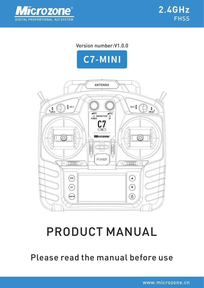
Microzone
Microzone C7-MINI product manual

Sony
Sony RMF-YD001 operating instructions
