manuals.online logo
Brands
  1. Home
  2. •
  3. Brands
  4. •
  5. ROBBE
  6. •
  7. Toy
  8. •
  9. ROBBE AMX-Jet User manual

ROBBE AMX-Jet User manual

Bau- und
Betriebsanleitung
AMX - Jet
No. 3270
No. 3271
AMX - Jet
2
Bau- und Bedienungsanleitung
©robbe Modellsport
No. 3270
No. 3271
©robbe Modellsport
AMX - Jet
3
No. 3270
No. 3271
Technische Daten
Spannweite: ca. 608 mm
Gesamtlänge: ca. 900 mm
Gesamtflächeninhalt: ca. 12 dm2
Fluggewicht: ca. 540 g
Gesamtflächenbelastung: ca. 45 g/dm2
Verehrter Kunde,
Sie haben sich für ein montiertes Modellflugzeug aus dem
Hause robbe Modellsport entschieden. Dafür danken wir
hnen.
Das Modell ist nach wenigen Handgriffen flugfertig. Um
hnen den sicheren Betrieb dieses Modells zu erleichtern,
sollten Sie unbedingt diese Anleitung und die beiliegenden
nformationsblätter vor der ersten nbetriebnahme genau
durchlesen.
Das Modell wird in 2 verschiedenen Lackierungsvarianten
geliefert. Die Dekorbilder sind bereits angebracht. n der
technischen Ausstattung unterscheiden sich die Modelle
nicht.
Die Anleitung ist für beide Versionen gültig. Die Abbildungen
zeigen das einfarbige Modell.
Alle Richtungsangaben wie z. B. „rechts“ sind in
Flugrichtung zu sehen.
Hinweis zum Antrieb
Als Antrieb ist ein Brushless-Aussenläufermotor mit einem
mpeller eingebaut.
Der Motor ist betriebsbereit mit dem Regler verbunden, der
Regler werksseitig eingestellt.
Zur nbetriebnahme ist es lediglich erforderlich, den Lipo-
Akku anzuschließen.
Adapterkabel für Equalizeranschluß, z. B. 8214
(zur Auswahl des Adapterkabels
die Anleitung des Ladegeräts beachten)
CT- 2 Steckkontakte 4077
für Flugakku
Schrumpfschlauch rot/schwarz 5149
Klettband 1713
Ersatz-Akku
Lipoly-Akku 3S 1P, 1300 mAh 32700004
Lieferbare Ersatzteile Bestell Nr.
mpellerset ohne Motor AMX Jet 32700001
Brushless Outrunner Motor AMX Jet 32700002
Kabinenhaube + Beschlagset AMX Jet 32700003
Baukasteninhalt
Rumpf mit Triebwerk, Regler und Servos.
Kabinenhaube transparent mit Cockpit.
Tragflächen mit Querrudern li. u .re und Servos.
Höhenleitwerk mit Rudern li. u. re
Seitenleitwerk
2x Querrudergestänge einseitig Z.-gekröpft
2x Höhenrudergestänge einseitig Z.-gekröpft
1x Lipo-Akku 3S 1P 1300 mAh 20 C
2x V-Kabel
Bau- und Bedienungsanleitung
Hinweis zur Fernsteueranlage
Zum Fernsteuern des Modells wird eine Anlage mit minde-
stens 4 Kanälen benötigt. Besonders empfohlen werden 2,4
GHz Anlagen.
Die Servos für die Querruder und für die Höhenruder sind
bereits eingebaut, wobei die Höhenruderservos und
Querruderservos über V-Kabel miteinander verbunden wer-
den.
Die Stromversorgung der Empfangsanlage erfolgt über das
eingebaute BEC des Reglers.
Der Regler befindet sich unter dem schwarzen Deckel auf
der Rumpfunterseite.
Bei der Funktionsprobe die Servos der Ruder mit der
Fernsteuerung in Neutralstellung bringen (Knüppel und
Trimmhebel am Sender in Mittelstellung).
Zur nbetriebnahme immer den Gasknüppel in Stellung
„Motor aus“ bringen, den Sender einschalten. Erst dann den
Akku anschließen.
Zum Ausschalten immer die Verbindung Akku - Motorregler
trennen, erst dann den Sender ausschalten.
Klebebarbeiten, geignete Klebstoffe
Alle Teile vor dem Verkleben immer erst “trocken”
anpassen.
Für Klebearbeiten Epoxy verwenden.
robbe ropoxy No. 5066
Uhu por (für Kunststoffdeckel)
Erforderliches Zubehör
Bezeichnung Bestell Nr.
Ladegerät z. B.
Compact Duo Power 6S EQ 8506
oder
Duo Power 8S-EQ 8504
AMX - Jet No. 3270
No. 3271
4
Bild 1
- Linke Höhenleitwerkshälfte in die Vertiefung des
Rumpfhecks kleben. Das Ruderhorn muss nach unten
weisen.
Auf korrekten Sitz achten.
Bild 2
- Rechte Höhenleitwerkshälfte in die Vertiefung des
Rumpfhecks kleben. Das Ruderhorn muss nach unten
weisen.
Auf korrekten Sitz achten.
Bild 3
- Die Gestänge in den Höhenruderservos einhängen
und an den Ruderhörnern anschließen. Die Einstellung
erfolgt bei der Funktionsprobe.
Bild 4
- Das Seitenleitwerk rechtwinklig zum Höhenleitwerk in
den Rumpf kleben.
Bau- und Bedienungsanleitung
©robbe Modellsport
12
34
AMX - Jet No. 3270
No. 3271
5
Bild 5
- Flächenhälften probeweise ansetzen und auf spaltfrei-
en Sitz am Übergang zum Rumpf prüfen. Falls erfor-
derlich, die Zunge geringfügig nacharbeiten.
Bild 6
- Eine Tragflächenhälfte am Rumpf verkleben. Auf kor-
rekten Profilverlauf am Übergang achten.
Bild 7
- Erst nach Aushärten des Klebstoffs die zweite Hälfte
ankleben.
Bild 8
- Die untere, schwarze Kunststoff-Abdeckung vorsich-
tig abziehen.
Bau- und Bedienungsanleitung
©robbe Modellsport
56
78
©robbe Modellsport
AMX - Jet
6
No. 3270
No. 3271
Bau- und Bedienungsanleitung
9Bild 9
- Die Kabel der Querruderservos in die Nuten des
Rumpfs eindrücken und nach innen verlegen.
Bild 10
- Die Kabel am losen V-Kabel anschließen. Auf farbglei-
che Zuordnung der Kabel achten.
Bild 11
- Das Reglerkabel sowie die beiden V-Kabel der Ruder
am Empfänger anschließen. Dabei die Anleitung der
Fernsteuerung betreffs der Kanalzuordnung und
Polung der Servokabel beachten.
( mpulskabel orange entspricht weißem Kabel bei
robbe-Futaba).
Bild 12
- Empfänger im Rumpf platzieren. Empfängerantenne
verlegen. Dazu die Anleitung der verwendeten
Fernsteuerung beachten.
10
11 12
AMX - Jet
7
Bild 13
- Die Sidewinder-Raketen aussen an den Tragflächen
verkleben. (Sidewinder-Raketen sind nur bei der sil-
ber eingefärbte Modellversion enthalten).
Bild 14
- Den Flugakku laden. Zum Anschluss des
Equalizerkabels ein zum Ladegerät passendes
Adapterkabel verwenden.
Bild 15
- Die Kabinenhaube wird durch einen
Magnetverschluss gehalten und kann nach oben
abgenommen werden.
Bild 16
-Den Sender einschalten, den Gasknüppel in die
Stellung „Motor aus“ bringen.
- Den geladenen Flugakku einlegen und anschließen.
Tonfolge des Reglers abwarten.
Bau- und Bedienungsanleitung
©robbe Modellsport
13 14
15 16
No. 3270
No. 3271
N
Sender, transmitter, émetteur
Motor “aus”
Motor “stopped”
Moteur "Arrêt"
Modell, model, modèle
AMX - Jet No. 3270
No. 3271
8
Bilder 17 und 18
- Die Kanalzuordnung der Ruder überprüfen, falls erfor-
derlich, die Stecker vertauschen.
-Die Neutralstellung der Ruder prüfen. gegebenen-
falls, durch Verdrehen der Gabelköpfe nachtrimmen.
- Stellen Sie sich hinter das Modell.
-Die Laufrichtung der Servos prüfen.
- Bei Betätigen des Querruderknüppels nach rechts (a)
muß sich das rechte Querruder (a) heben, das linke (b)
senken.
- Ziehen des Höhenruderknüppels zum Körper hin (c)
bewirkt, dass sich die Hinterkanten der Höhenruder
heben, (c).
- Bei vertauschten Ruderfunktionen Servo-Reverse des
Senders für die entsprechende Funktion betätigen.
- Alle Anlenkungen auf festen Sitz und Leichtgängigkeit
prüfen.
Bild 19
Motorlauf
- Das Modell festhalten.
-Vor dem Modell dürfen sich keine Gegenstände wie
Lappen, Werkzeuge oder ähnliches befinden, da
diese durch den Impeller angesaugt werden können.
-Gas geben. Der Motor muss anlaufen. Am Heck des
Modells muß ein deutlicher Luftstrom spürbar sein.
- Gasknüppel wieder in die Stellung “Motor aus” brin-
gen.
- Erst die Verbindung Akku - Regler trennen, dann den
Sender ausschalten.
Bau- und Bedienungsanleitung
©robbe Modellsport
18
19
Querruder, Aileron, Aileron
a
b
Höhenruder, Elevator, Profondeur
c
c
d
d
ca. 10 mm
ca. 10 mm
Motor, Motor, Moteur
Motor “ein”
Motor “on”
Moteur "en marche"
a
b
rechts, right, droite
ca. 8 mm
ca. 8 mm
17
AMX - Jet No. 3270
No. 3271
9
Bilder 20 und 21
- Den schwarzen Kunststoffdeckel mit Uhu-por aufkle-
ben. Dabei nur den inneren Rand des Deckels ein-
streichen.
Bild 22
- Den Akku zum folgenden Auswiegen einlegen, nicht
anschließen.
- Den Schwerpunkt gemäß Unteransicht beidseitig auf
dem Rumpf anzeichnen.
- Das Modell im Schwerpunkt C.G. unterstützen und
auspendeln lassen. Die dealstellung ist erreicht, wenn
das Modell mit leicht nach unten hängendem
Vorderteil in der Waage bleibt.
- Flugakku, falls erforderlich entsprechend verschieben.
- Die Akkuposition im Rumpf anzeichnen, damit der
Akku bei einem Wechsel wieder in der gleichen Lage
eingebaut werden kann.
- Den Akku in der gefundenen Position zusätzlich mit
Schaumstoffresten fixieren, damit er während des
Fluges nicht verrutschen und die
Schwerpunktposition verändern kann.
- Das Modell ist nach erneutem Laden des Akkus start-
bereit.
Bau- und Bedienungsanleitung
©robbe Modellsport
20
21
22
C.G.
65-70 mm
C.G.
AMX - Jet No. 3270
No. 3271
10
Bilder 23 - 26, Zugang zu Impeller und Regler
- Im Wartungs- oder Reparaturfall ist das
Impellertriebwerk von unten zugänglich.
Zum Öffnen des Rumpfs wie folgt vorgehen:
- Den schwarzen Kunststoffdeckel öffnen und entfer-
nen.
- Die kleinen Verkleidungen für die Schrauben abneh-
men.
- Die Schrauben lösen.
- Den Rumpfdeckel abnehmen.
- Nach Lösen der Steckverbindungen können Regler
oder mpeller ausgebaut werden. Farbzuordnung der
Kabel notieren.
- Den Zusammenbau in umgekehrter Reihenfolge vor-
nehmen. Die Verkleidungen der Schrauben können
mit einem Tropfen Kontaktkleber gesichert werden.
Bau- und Bedienungsanleitung
©robbe Modellsport
23 24
25 26
AMX - Jet No. 3270
No. 3271
11
Einfliegen, Flughinweise
- Vor dem Erstflug die Abschnitte „Routineprüfungen vor
dem Start“ und „Modellbetrieb“ im Abschnitt
„Sicherheitshinweise“ beachten.
- Zum Einfliegen des Modells sollten Sie sich einen mög-
lichst windstillen Tag aussuchen.
- Als Gelände für die ersten Flüge eignet sich eine große,
ebene Wiese ohne Hindernisse (Bäume, Zäune,
Hochspannungsleitungen etc.).
- Nochmals eine Funktionsprobe durchführen.
- Für den Handstart sollte ein Helfer anwesend sein, der
das Modell mit nicht zu geringem Schub in die Luft beför-
dern kann.
Bau- und Bedienungsanleitung
©robbe Modellsport
- Der Start erfolgt genau gegen den Wind.
- Den Motor einschalten und das Modell mit einem kräftigen
Schwung horizontal gegen den Wind starten.
- Den AMX - Jet geradeaus fliegen lassen, keine Kurven in
Bodennähe einleiten.
- Ruder falls erforderlich nachtrimmen, bis ein gleichmäßi-
ger Steigflug erreicht ist.
- Die Reaktionen des Modells auf die Ruderausschläge prü-
fen. Gegebenenfalls die Ausschläge nach der Landung
entsprechend vergrößern oder verkleinern.
- Die Mindestfluggeschwindigkeit in ausreichender
Sicherheitshöhe erfliegen.
- Die Landung mit ausreichend Fahrt einleiten.
- War ein Nachtrimmen erforderlich, so werden die
Gestängelängen nach der Landung korrigiert und die
Trimmhebel am Sender wieder in Mittelstellung gebracht,
so daß für die folgenden Flüge beidseitig der volle
Trimmweg zur Verfügung steht.
robbe Modellsport GmbH & Co. KG
Technische Änderungen vorbehalten
Service-Adressen
Dieses Symbol bedeutet, dass elektrische und
elektronische Kleingeräte am Ende ihrer Nutzungs-
dauer, vom Hausmüll getrennt, entsorgt werden
müssen.
Entsorgen Sie das Gerät bei hrer örtlichen kommu-
nalen Sammelstelle oder Recycling-Zentrum. Dies gilt für alle Län-
der der Europäischen Union sowie anderen Europäischen Ländern
mit separatem Sammelsystem.
Hiermit erklärt die robbe Modellsport GmbH & Co. KG,
dass sich dieses Gerät in Übereinstimmung mit den grund-
legenden Anforderungen und anderen relevanten
Vorschriften der entsprechenden CE Richtlinien befindet.
Die Original-Konformitätserklärung finden Sie im nternet
unter www.robbe.com, bei der jeweiligen
Gerätebeschreibung durch Aufruf des Logo-Buttons
"Conform".
Land
Firma
Strasse
Stadt
Telefon Fax
E-Mail
Andorra
Sorteney
Santa Anna, 13
AND-00130 Les escaldes-
Princip. D'Andorre
00376-862 865 00376-825 476
[email protected]
Dänemark
Nordic Hobby A/S
Bogensevej 13
DK-8940 Randers SV
0045-86-43 61 00 0045-86-43 77 44
[email protected]
Deutschland
robbe-Service
Metzloser Str. 36
D-36355 Grebenhain
0049-6644-87-777 0049-6644-87-779
[email protected]
England
robbe-Schlüter UK
LE10-UB
GB-LE10 3DS Leicestershire
0044-1455-637151 0044-1455-635151
[email protected]
Frankreich
S.A.V Messe
6, Rue Usson du Poitou, BP 12
F-57730 Folschviller
0033 3 87 94 62 58 0033-3-87 94 62 58
[email protected]
Griechenland
TAG Models Hellas
18,Vriullon Str.
GR-14341 New Philadelfia/Athen
0030-2-102584380 0030-2-102533533
[email protected]
talien
MC-Electronic
Via del Progresso, 25
-36010 Cavazzale
di Monticello C.Otto (Vi)
0039 0444 945992 0039 0444 945991
[email protected]
Niederlande/Belg.
Jan van Mouwerik
Slot de Houvelaan 30
NL-3155 Maasland
0031-10-59 13 594 0031-10-59 13 594
[email protected]
Norwegen
Norwegian Modellers
Box 2140
N-3103 Toensberg
0047-333 78 000 0047-333 78 001
[email protected]
Österreich
robbe-Service
Puchgasse 1
A-1220 Wien
0043-1259-66-52 0043-1258-11-79
[email protected]
Schweden
Minicars Hobby A.B.
Bergsbrunnagatan 18
S-75323 Uppsala
0046-186 06 571 0046-186 06 579
[email protected]
Schweiz
Spahr Elektronik
Gotthelfstr. 12
CH-2543 Lengau
0041-32-652 23 68 0041-32 653 73 64
[email protected]
Slowakische Rep.
vo Marhoun
Horova 9
CZ-35201 AS
00420 351 120 162
[email protected]
Spanien
robbe-Service
Metzloser Str. 36
D-36355 Grebenhain
0049-6644-87-777 0049-6644-87-779
[email protected]
Tschech. Rep.
vo Marhoun
Horova 9
CZ-35201 AS
00420 351 120 162
[email protected]
©robbe Modellsport
robbe Modellsport GmbH & Co. KG
Metzloserstr. 36
Telefon: 06644 / 87-0
D36355 Grebenhain
www.robbe.com
robbe-Form BAAI
rrtum und technische Änderungen vorbehalten
Copyright robbe-Modellsport 2008
Kopie und Nachdruck, auch auszugsweise, nur mit schriftlicher
Genehmigung der robbe-Modellsport GmbH & Co.KG
Assembly and operating instructions
otice de montage et de pilotage
Istruzioni di montaggio e d’uso
Instrucciones de montaje y manejo
Stavební a provozní návod
AMX - Jet
o. 3270
o. 3271
2
©robbe Modellsport
AMX - Jet o. 3270
o. 3271
AMX - Jet
3
Specification
Wingspan: approx. 608 mm
Overall length: approx. 900 mm
Total surface area: approx. 12 dm²
All-up weight: approx. 540 g
Total surface area loading: approx. 45 g / dm²
Dear customer,
Congratulations on your choice of a factory-assembled
model aircraft from the robbe Modellsport range. Many
thanks for placing your trust in us.
Very little work is required to prepare the model ready for
flying. You can make it as easy as possible to operate your
new aeroplane safely by taking the trouble to read right
through these instructions attentively, together with the
separate information sheets, before you fly it for the first
time.
The model is available in two different colour schemes. The
decals are already applied. In terms of technical features the
two models are identical.
These instructions apply to both versions; the illustrations
show the single-colour model.
All directions, such as “right-hand”, are as seen from the
tail of the model, looking forward.
The power system
The model is powered by a brushless outrunner motor and
ducted fan, both of which are factory-installed.
The motor is connected to the speed controller, ready to
run, and the controller is factory-adjusted.
All you have to do is connect the LiPo flight battery to the
speed controller.
The radio control system
To fly the AMX - Jet you need a radio control system with at
least four channels. We particularly recommend 2.4 G z
systems.
The servos for the ailerons and the elevators are factory-
installed; the elevator servos and aileron servos are wired in
parallel using Y-leads.
The power supply for the receiving system is drawn from
the speed controller’s integral BEC system.
The speed controller is located under the black plastic
hatch on the underside of the fuselage.
To check the model’s working systems, first set the control
surface servos to neutral from the transmitter, after check-
ing that the transmitter sticks and trims are at centre.
When you wish to fly the model, always move the throttle
stick to the “Motor OFF” position before switching the
transmitter on, and only then connect the flight battery to
the speed controller.
Switch off in the reverse order: disconnect the battery from
the speed controller first, and only then switch the transmit-
ter off.
Gluing techniques, adhesives
Check the fit of parts “dry” before reaching for the glue bot-
tle.
Epoxy adhesive should be used for almost all joints:
robbe ropoxy No. 5066
U U por (for plastic hatch cover)
Additional parts required
Item Order o.
Battery charger, e.g.
Compact Duo Power 6S EQ 8506
or
Duo Power 8S EQ 8504
Adapter lead for Equalizer socket, e.g. 8214
(please refer to the charger instructions
for help with selecting the appropriate
adapter lead)
CT 2 connectors 4077
for flight battery
Red / black heat-shrink sleeve 5149
Velcro (hook-and-loop) tape 1713
Replacement battery
LiPoly battery, 3S 1P, 1300 mAh 32700004
Replacement parts Order o.
AMX - Jet impeller set, excl. motor 32700001
AMX - Jet brushless outrunner motor 32700002
AMX - Jet canopy + fittings set 32700003
Kit contents
Fuselage, with motor, speed controller and servos
Clear canopy and cockpit
Left / right wing panels with ailerons and servos
Left / right tailplane panels with elevators
Fin
2 x aileron pushrod, one Z-bend
2 x elevator pushrod, one Z-bend
1 x LiPo battery, 3S 1 P 100 mAh 20 C
2 x Y-lead
Fig. 1
- Glue the left-hand tailplane panel in the recess in the tail
end of the fuselage. Note that the elevator horn must be
on the bottom.
Check that the panel is located correctly.
Assembly and operating instructions
©robbe Modellsport
o. 3270
o. 3271
AMX - Jet
4
Fig. 2
- Glue the right-hand tailplane panel in the recess in the tail
end of the fuselage. Note that the elevator horn must be
on the bottom.
Check that the panel is located correctly.
Fig. 3
- Connect the pushrods to the elevator servos, and then to
the elevator horns. Final adjustments are made at a later
stage.
Fig. 4
- Glue the fin to the fuselage, ensuring that it is exactly ver-
tical.
Fig. 5
- Offer up the wing panels to the fuselage and check that
they fit neatly, without gaps at the joint line. Trim the pro-
jecting lugs slightly if necessary.
Fig. 6
- Glue one wing panel to the fuselage. Check that it lines up
correctly with the root fairing.
Fig. 7
- Allow the glue to set hard before repeating the procedure
with the second wing panel.
Fig. 8
- Carefully peel off the black plastic hatch cover on the
underside of the fuselage.
Fig. 9
- Press the aileron servo leads into the channels in the
fuselage, and route them into the interior.
Fig. 10
- Connect the servo leads to the loose Y-leads. Ensure that
the wire colours match up correctly.
Fig. 11
- Connect the speed controller lead and the two Y-leads to
the receiver. You will need to refer to the RC system
instructions for the correct channel sockets and servo
lead polarity. (the orange signal wire corresponds to the
white wire in robbe-Futaba systems).
Fig. 12
- Place the receiver in the fuselage, and deploy the receiv-
er aerial. Refer to the RC system instructions for more
information on this.
Fig. 13
- Glue the Sidewinder rockets to the wingtips as shown.
Note: the Sidewinder rockets are only included in the ver-
sion with the silver finish.
Fig. 14
- Charge the flight battery; connect the Equalizer lead using
an adapter lead matching your charger.
Fig. 15
- The canopy is held in place by a magnet, and can simply
be lifted off.
Fig. 16
- Switch the transmitter on, and move the throttle stick to
the “Motor OFF” position.
- Place the fully charged flight battery in the fuselage and
connect it to the speed controller. Wait until the controller
emits a sequence of beeps.
Figs. 17 and 18
- Check that the control surfaces respond to the appropri-
ate movements of the transmitter sticks. If not, swap over
the connectors at the receiver.
- Check the neutral position of the control surfaces; you
may need to screw the clevises in or out to correct any
discrepancy.
- Stand behind the model.
- Check the direction of rotation of the servos:
- Move the aileron stick to the right (a), and the right aileron
(a) must rise, the left aileron (b) fall.
- Pull the elevator stick back towards you (c), and the trail-
ing edge of both elevators should rise (c).
- If either function works the wrong way round, correct it
using your transmitter’s servo reverse facility for that
channel.
- Check that all control surface linkages are secure, and
that the control surfaces move freely in both directions.
Fig. 19
Checking the power system
- old the model securely.
- Remove any loose objects such as cloths, tools or similar
from the area in front of the model, as they could easily be
sucked into the ducted fan.
Assembly and operating instructions
©robbe Modellsport
o. 3270
o. 3271
AMX - Jet
5
- Open the throttle (stick forward): the motor should now
run, and you should feel a strong flow of air exiting the tail
end of the model.
- Move the throttle stick back to the “Motor OFF” position.
- Disconnect the battery from the speed controller, then
switch the transmitter off.
Figs. 20 and 21
- Stick the black plastic hatch cover in place again using
U U-por; apply the adhesive only to the inside edges of
the cover.
Fig. 22
- The next step is to check the model’s balance: place the
flight battery in its compartment, but do not connect it.
- Mark the Centre of Gravity on both sides of the fuselage;
the position is stated in the photo.
- Support the model at the marked points and allow it to
hang freely. When correctly balanced the aeroplane will
remain horizontal, with the nose slightly down.
- If necessary, adjust the position of the flight battery to
achieve the correct CG.
- Mark the battery location in the fuselage, so that you can
be sure of positioning it correctly after recharging it.
- Pack scrap pieces of foam round the battery in its final
position, otherwise there is a danger of it shifting in flight
and altering the model’s balance.
- Top up the flight battery, and the model is ready for its
first flight.
Figs. 23 - 26, access to the ducted fan unit and speed
controller
- The ducted fan unit is accessible from underneath if you
need to carry out maintenance work or a repair.
This is the procedure for opening the fuselage:
- Open and remove the black plastic hatch cover.
- Remove the small fairings over the retaining screws.
- Undo the retaining screws.
- Remove the fuselage hatch.
- Disconnect the plugs and sockets: the speed controller
and / or the ducted fan unit can now be removed. Note
down the sequence of the wire colours.
- Reverse the procedure to re-install these items. The fair-
ings for the screws can be secured with a drop of contact
cement.
Test-flying, notes on flying the aeroplane
- Please read the sections entitled “Routine pre-flight
checks” and “Flying the model” in the Safety otes
before attempting to fly the AMX - Jet for the first time.
- For the first flight you should wait for a day with no more
than a gentle breeze.
- A good flying site is a large, flat, open field. Keep well
away from trees, fences, high-tension overhead cables
and other potentially dangerous obstacles.
- Carry out a complete check of the working systems.
- We recommend that you ask an experienced modeller to
help you initially; he should be confident of giving the
model a fairly powerful hand-launch.
- The model must be launched directly into any wind
- Switch the motor on, and launch the aeroplane strongly
into the wind, with the fuselage and wings level.
- Allow the AMX - Jet to fly straight and level initially; don’t
try to turn it when it is close to the ground.
- Adjust the trims if necessary so that the model settles into
a steady climb.
- Check the model’s response to control commands from
the transmitter. You may need to increase or reduce the
control surface travels once the model is back on the
ground.
- Take the aeroplane up to a safe height and check its
stalling speed.
- Keep the speed well up on the landing approach to avoid
stalling.
- If you had to move the trims during the flight, correct the
mechanical linkages before flying again. This allows you
to re-centre the trims, so that full trim travel is available for
subsequent flights.
robbe Modellsport GmbH & Co. KG
We reserve the right to introduce technical modifications.
Assembly and operating instructions
©robbe Modellsport
o. 3270
o. 3271
AMX - Jet
6
Caractéristiques techniques
Envergure : approx. 608 mm
Longueur totale : approx. 900 mm
Surface alaire totale : env. 12 dm²
Poids en ordre de vol : approx. 540 g
Charge alaire totale : env. 45 g/dm²
Cher Client,
Vous avez choisi un modèle de planeur entièrement assem-
blé de la Sté robbemodellsport. Nous vous en remercions.
Le modèle est prêt à voler après quelques opérations de
finition. Afin d'exploiter aux mieux les possibilités de ce
modèle et de le faire voler en toute sécurité, nous vous
recommandons la lecture attentive de la présente notice et
des feuillets d'information joints avant d'effectuer votre pre-
mière sortie.
Le modèle est proposé avec 2 variantes de peinture. Les
autocollants de décoration sont déjà appliqués.
L'équipement technique des modèles est identique.
La notice concerne les deux versions. Les illustrations
présentent le modèle monochrome.
Toutes les indications directionnelles telles que „droite“,
par exemple, sont à considérer dans le sens du vol.
Consignes concernant la motorisation du modèle
L’entraînement est constitué d’un moteur sans balais à
induit externe avec une hélice propulsive intégrée.
Le moteur est relié au variateur en l’état de marque et le
variateur est réglé en usine.
Pour la mise en service, il suffit simplement de raccorder
l'accu LiPo.
Consigne concernant l'ensemble de radiocommande
Pour piloter le modèle, il faut disposer d’un ensemble de
radiocommande disposant d’au moins 4 voies. Nous
recommandons particulièrement les ensembles de radio-
commande 2,4 G z.
Sont déjà implantés les servos des ailerons et des gou-
vernes de profondeur, les servos de gouverne de pro-
fondeur et des ailerons étant reliés entre eux par un cordon
Y.
L’alimentation électrique de l’ensemble de réception est
assurée par le système BEC intégré du variateur.
Le variateur se trouve sous le couvercle noir se trouvant
dans l’intrados du fuselage.
Lors de l'essai des fonctions, amener les servos au neutre
à l'aide de l'ensemble de radiocommande (manches et dis-
positifs de réglage de précision (trim) en position médiane).
Pour la mise en service disposer systématiquement le
manche des gaz en position „Moteur arrêt“, mettre
l'émetteur en marche. Raccorder d'abord l'accu.
Pour couper l'ensemble de radiocommande désolidariser
d'abord la connexion entre l'accu et le moteur, en suite
coupe l'émetteur.
Travaux de collage, colles appropriées
Ajuster d’abord tous les éléments “à sec” avant de les coller
définitivement.
Pour les travaux de collage, utiliser de la colle époxy.
robbe ropoxy , Réf. 5066
Uhu por (pour le couvercle en plastique)
Accessoires nécessaires à la mise en œuvre du modèle
Désignation Réf.
Chargeur, par exemple
Compact Duo Power 6S EQ 8506
ou
Duo Power 8S-EQ 8504
cordon-adaptateur
pour raccorder un égaliseur, par exemple 8214
(pour choisir le cordon-adaptateur observez
les instructions fournies par le chargeur)
contacts de connexion CT-2 4077
pour l’accu d’alimentation du moteur
gaine thermorétractable rouge / noir 5149
bande velcro 1713
Accu de rechange
1 accu Lipoly 3S 1P, 1300 mAh 32700004
Pièces détachées disponibles Réf.
kit turbine de propulsion sans moteur AMX Jet 32700001
moteur sans balais à induit externe AMX Jet 32700002
verrière de cabine + kit d'accastillage AMX Jet 32700003
Contenu de la boîte de construction
fuselage avec groupe propulseur, variateur et servos.
verrière de cabine transparente avec cockpit.
demi-ailes avec ailerons gauche et droite et servo
plans fixes horizontaux avec gouvernes gauche et droit
plan fixe vertical, dérive
2x timonerie d'aileron avec une extrémité en Z
2x timonerie de profondeur avec une extrémité en Z
1x Accu LiPo 3S 1P 1300 mAh 20 C
2x cordon Y
Fig. 1
- Coller la demi-gouverne de profondeur gauche dans la
concavité de la queue du fuselage. Le guignol doit être
orienté vers le bas.
Veiller au bon ajustement.
Fig. 2
- Coller la demi-gouverne de profondeur droite dans la
concavité de la queue du fuselage. Le guignol doit être
orienté vers le bas. Veiller au bon ajustement.
Notice de montage et de mise en œuvre
©robbe Modellsport
réf. 3270
réf. 3271
AMX - Jet
7
Notice de montage et de mise en œuvre
Fig. 3
- Accrocher la timonerie aux servos de profondeur et les
raccorder aux guignols. Le réglage définitif interviendra
lors des essais de fonctionnement.
Fig. 4
- Coller la dérive dans le fuselage à angle droit par rapport
au stabilisateur.
Fig. 5
- Mettre les demi-ailes en place provisoirement et en con-
trôler l'assise à la transition vers le fuselage qui ne doit
pas présenter de jeu. Si nécessaire, retravailler légère-
ment la languette.
Fig. 6
- Coller une des demi-ailes au fuselage. Veiller á la conti-
nuité du profil au niveau de la transition.
Fig. 7
- Lorsque la colle est sèche, coller la seconde demi-aile.
Fig. 8
- Retirer avec précaution le couvercle inférieur noir.
Fig. 9
- Presser les cordons des servos d'ailerons dans les
encoches du fuselage et les agencer vers l'intérieur.
Fig. 10
- Raccorder les cordon au cordon Y flottant. veiller à rac-
corder les brins en fonction de leur couleur.
Fig. 11
- Raccorder le cordon du variateur et les deux cordons Y
des gouvernes au récepteur. Consultez la notice de
l'ensemble de radiocommande pour ce qui concerne
l'affectation des voies et la polarité des cordons de servo.
(Le brin d'impulsion orange correspond au brin blanc
chez robbe-Futaba).
Fig. 12
- Disposer le récepteur dans le fuselage. Agencer l'antenne
du récepteur. Pour ce faire, tenir compte des informations
fournies par la notice de l'ensemble de radiocommande
utilisé.
Fig. 13
- Coller les missiles air-air (Sidewinder) à l'extérieur sur les
demi-ailes. (Les missiles ne sont livrés qu'avec la version
du modèle teintée argent).
Fig. 14
- Charger l'accu d'alimentation du moteur. Pour raccorder
les cordon de l'égaliseur utilisez un cordon-adaptateur
approprié au chargeur.
Fig. 15
- la verrière de cabine dispose d’une fermeture magnétique
et peut être simplement retirée vers le haut.
Fig. 16
- Mettre l'émetteur en marche, disposer le manche des gaz
en position „Moteur arrêt“.
- Mettre l'accu d'alimentation du moteur en place dans le
fuselage et le raccorder.
Attendre la séquence des sons du variateur.
Fig. 17 et 18
- Contrôlez l'affectation des canaux par rapport aux gou-
vernes et, si nécessaire, intervertissez les connecteurs.
- Contrôler la position neutre des gouvernes. Si nécessaire,
effectuer les ajustements nécessaires en tournant les
chapes.
- Installez-vous derrière le modèle.
- Contrôler le sens de rotation des servos.
- En déplaçant le manche des ailerons vers la droite (a), il
faut que le bord de fuite de l'aileron droit (a) s'élève et que
celui de l'aileron gauche (b) descende.
- Le fait de tirer le manche de profondeur vers soi (c)
provoque un débattement des gouvernes de profondeur
vers le haut (c).
- Si des fonctions des servos des gouvernes sont inver-
sées, les corriger à l'aide du dispositif électronique
d'inversion des servos sur l'émetteur.
- Vérifier que l’ensemble de la timonerie est parfaitement
logée et en contrôler la souplesse de déplacement.
Fig. 19
Fonctionnement du moteur
- Maintenir le modèle fermement.
- Éviter que devant le modèle se trouvent des objets tels
que des chiffons, de l’outillage ou autres car ils risquent
d’être aspirés par la turbo-propulsion.
- Donner des gaz. Le moteur doit démarrer. À l’arrière du
modèle on doit sentir un courant d’air évident.
- Amener le manche des gaz sur l’émetteur en position
“moteur arrêt”.
- Désolidariser d'abord la liaison accu – variateur avant de
couper l'émetteur.
©robbe Modellsport
réf. 3270
réf. 3271
AMX - Jet
8
Fig. 20 et 21
- Coller le couvercle en plastique noir avec de la colle Uhu-
por. Pour ce faire, n'enduire de colle que le bord intérieur
du couvercle.
Fig. 22
- Installer l’accu pour réaliser l’équilibrage qui suit sans
toutefois le raccorder pour l’instant.
- Reporter bilatéralement l’emplacement du centre de
gravité sur le fuselage selon les indications de la vue du
dessous
- Caler le modèle au niveau de son centre de gravité et le
laisser en équilibre. Le modèle atteint sa position idéale
lorsqu'il reste en équilibre sur les doigts avec le nez
légèrement piqueur (plus bas que la queue).
- Si nécessaire, décaler l’accu d’alimentation du moteur en
conséquence afin d’équilibrer le modèle.
- Repérer la position de l'accu dans le fuselage afin d'être
en mesure de replacer l'accu exactement au même
endroit après sa charge ou son remplacement.
- Fixer l'accu dans la position établie en plus avec des
chutes de mousse plastique afin qu'il ne puisse se
déplacer pendant la séance de vol et afin d'éviter ainsi de
modifier la position du centre de gravité.
- Une fois que l'accu a été rechargé, le modèle est à nou-
veau en ordre de décoller.
Fig. 23 à 26 Accès à la turbine et au variateur
- Pour les travaux de maintenance et les réparations
éventuelles, le turbopropulseur est accessible par
dessous.
Pour ouvrir le fuselage, procéder comme suit :
- ouvrir le couvercle en plastique noir et le retirer.
- Retirer les petits parements des vis.
- Desserrer les vis.
- Retirer le couvercle du fuselage.
- Une fois que les connecteurs ont été retirés, il est possi-
ble de démonter le variateur et la turbine. Noter
l'affectation chromatique des brins.
- Pour le montage, procéder dans l'ordre inverse. Il est
possible de fixer les parements de vis avec une goutte de
colle cyanoacrylate.
Le premier vol, consignes de pilotage
- Avant le premier vol, effectuer les „contrôles de routine
avant le décollage“ et tenir compte des consignes de
sécurité de „mise en œuvre du modèle“.
- Pour le premier vol, choisir un jour sans vent ou à vent
faible.
- Comme terrain pour les premiers vols, on choisira de
préférence une grande prairie exempte d’obstacles
(arbre, grillage, lignes à haute tension, etc.)
- Effectuer à nouveau un essai des fonctions.
- Pour le lancement du modèle à la main, il est recom-
mandé de lancer le modèle avec une bonne poussée
dans l'air.
- Le décollage du modèle intervient contre le vent.
- Mettre le moteur en marche et lancer le modèle avec un
bon élan exactement contre le vent à l’horizontale.
- Laisser le modèle AMX-Jet effectuer un vol rectiligne, ne
pas virer à proximité du sol.
- Si nécessaire, rectifier le réglage des gouvernes afin
d'obtenir un vol ascensionnel régulier.
- Contrôler les réactions du modèle aux débattements des
gouvernes. Si nécessaire, après atterrissage, rectifier les
débattements, en plus ou en mois, au niveau des tringles.
- Ne voler à vitesse minimale que lorsque le modèle se
trouve à une altitude de sécurité suffisante.
- Engager l'atterrissage avec une vitesse suffisante.
- Si le comportement du planeur vous a contraint de mod-
ifier la position des dispositifs de réglage de précision
(trims), après l'atterrissage, rectifier au niveau des tringles
afin de rétablir la position neutre des trims sur l'émetteur
pour disposer de l'ensemble de leur course lors du vol
suivant.
robbe modellsport GmbH & Co. KG
Sous réserve de modification technique
Notice de montage et de mise en œuvre
©robbe Modellsport
réf. 3270
réf. 3271

This manual suits for next models

2

Other ROBBE Toy manuals

ROBBE RAT PNP 2636 Instruction Manual

ROBBE

ROBBE RAT PNP 2636 Instruction Manual

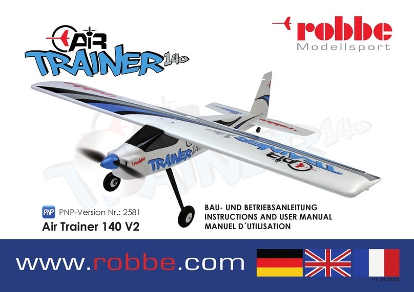
ROBBE Air Trainer 140 V2 User manual

ROBBE

ROBBE Air Trainer 140 V2 User manual

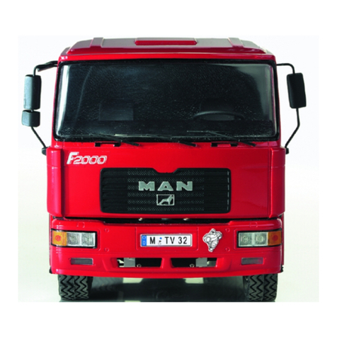
ROBBE MAN F2000 Evolution User manual

ROBBE

ROBBE MAN F2000 Evolution User manual

ROBBE AIRBULL 3129 User manual

ROBBE

ROBBE AIRBULL 3129 User manual

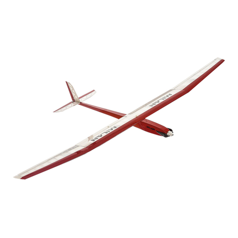
ROBBE MILAN Instruction Manual

ROBBE

ROBBE MILAN Instruction Manual

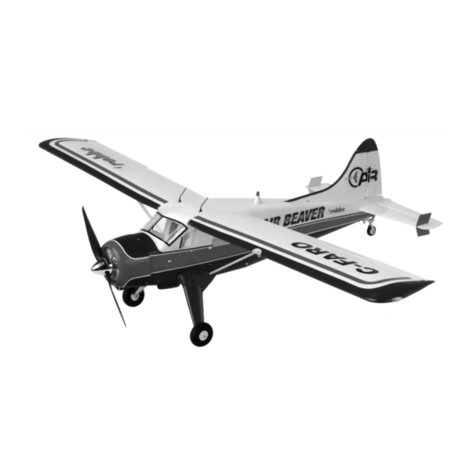
ROBBE Air Beaver User manual

ROBBE

ROBBE Air Beaver User manual

ROBBE AIR TRAINER 140 ARF Operating instructions

ROBBE

ROBBE AIR TRAINER 140 ARF Operating instructions

ROBBE Pitts S 1 ARF User manual
ROBBE

ROBBE Pitts S 1 ARF User manual

ROBBE Cloud Dancer User manual

ROBBE

ROBBE Cloud Dancer User manual

ROBBE Nino 3267 User manual

ROBBE

ROBBE Nino 3267 User manual

ROBBE Twister 3121 User manual

ROBBE

ROBBE Twister 3121 User manual

ROBBE Arcus Talent ARF Operating instructions

ROBBE

ROBBE Arcus Talent ARF Operating instructions

ROBBE Dimona User manual

ROBBE

ROBBE Dimona User manual

ROBBE Eolo R 22 User manual

ROBBE

ROBBE Eolo R 22 User manual

ROBBE BUSSARD river survey boat 1196 Instruction Manual

ROBBE

ROBBE BUSSARD river survey boat 1196 Instruction Manual

ROBBE Cessna 182 User manual

ROBBE

ROBBE Cessna 182 User manual

ROBBE JETHROW 500 Instruction Manual

ROBBE

ROBBE JETHROW 500 Instruction Manual

ROBBE ASW 15B Instruction Manual

ROBBE

ROBBE ASW 15B Instruction Manual

ROBBE SLIDER QE 2686 Instruction Manual

ROBBE

ROBBE SLIDER QE 2686 Instruction Manual

ROBBE SPEEDY WING Instruction Manual

ROBBE

ROBBE SPEEDY WING Instruction Manual

ROBBE Pilatus PC21 Nano-Racer Operating instructions

ROBBE

ROBBE Pilatus PC21 Nano-Racer Operating instructions

ROBBE Lightning 46 User manual

ROBBE

ROBBE Lightning 46 User manual

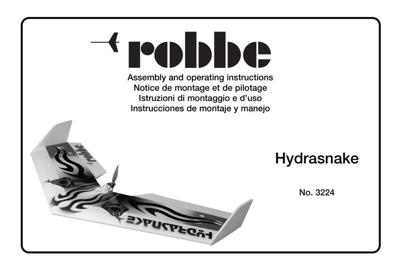
ROBBE Hydrasnake User manual

ROBBE

ROBBE Hydrasnake User manual

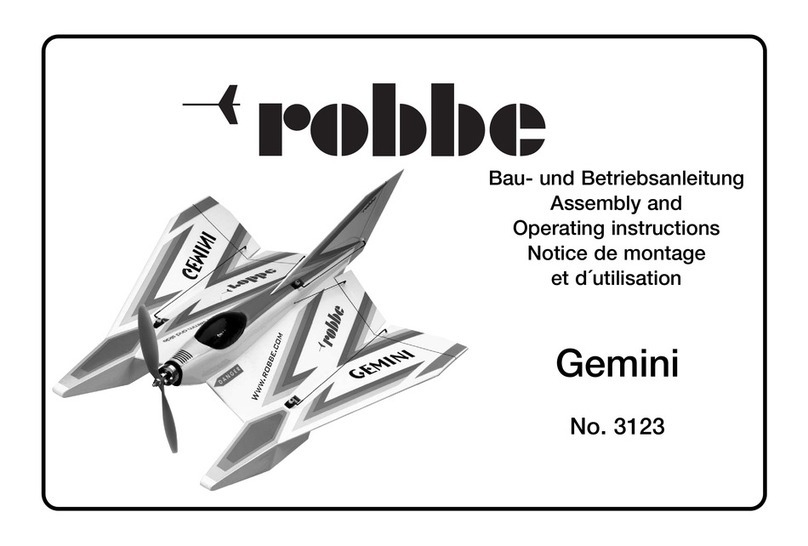
ROBBE Gemini User manual

ROBBE

ROBBE Gemini User manual

Popular Toy manuals by other brands

MODSTER AN-269625 CLIK R2 ROT user manual

MODSTER

MODSTER AN-269625 CLIK R2 ROT user manual

Enabling Devices 2336 user guide

Enabling Devices

Enabling Devices 2336 user guide

XtremeAIR sbach 342 user manual

XtremeAIR

XtremeAIR sbach 342 user manual

The World Models Manufacturing LA RACER-40 instruction manual

The World Models Manufacturing

The World Models Manufacturing LA RACER-40 instruction manual

roco Re 465 BLS Stockhorn operating manual

roco

roco Re 465 BLS Stockhorn operating manual

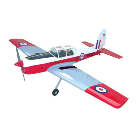
arf YAK 55M instruction manual

arf

arf YAK 55M instruction manual

Hasbro Spiderman 3 Electronic Web Blaster 69116 instruction manual

Hasbro

Hasbro Spiderman 3 Electronic Web Blaster 69116 instruction manual

MGA RAINBOW HIGH 503163 quick start guide

MGA

MGA RAINBOW HIGH 503163 quick start guide

Hasbro Radical Rollin' Rachel 73800 instruction manual

Hasbro

Hasbro Radical Rollin' Rachel 73800 instruction manual

Enabling Devices Cyclone 7008 user guide

Enabling Devices

Enabling Devices Cyclone 7008 user guide

Black Horse Model CHIPMUNK Instruction manual book

Black Horse Model

Black Horse Model CHIPMUNK Instruction manual book

Chipolino MERRY FISHES Instruction manual for use

Chipolino

Chipolino MERRY FISHES Instruction manual for use

Eduard EA-18G exterior quick start guide

Eduard

Eduard EA-18G exterior quick start guide

LeapFrog Tad's Fridge Phonics Magnetic Letter Set Parents' guide

LeapFrog

LeapFrog Tad's Fridge Phonics Magnetic Letter Set Parents' guide

Chicco GoGoFriends ROCK-a-BEE instruction manual

Chicco

Chicco GoGoFriends ROCK-a-BEE instruction manual

Black Horse Model Sea Futy Instruction manual book

Black Horse Model

Black Horse Model Sea Futy Instruction manual book

Reely Sky Phonix operating instructions

Reely Sky

Reely Sky Phonix operating instructions

Carrera 25143 COOL RODS Assembly and operating instructions

Carrera

Carrera 25143 COOL RODS Assembly and operating instructions

manuals.online logo
manuals.online logoBrands
  • About & Mission
  • Contact us
  • Privacy Policy
  • Terms and Conditions

Copyright 2025 Manuals.Online. All Rights Reserved.