arf YAK 55M User manual

SPECIFICATION
Wingspan : 1,810 mm. 71.26 in.
Length : 1,600 mm. 62.99 in.
Weight : 4.6kg. 10.12 lbs.
Radio : 6 channels.
Servo : 06 servos.
Engine : 30 cc
MadeinVietnam.
Instruction Manual book
ITEM CODE: BH111

YAK 55 - ITEM CODE:BH111. Instruction Manual
2
This instruction manual is designed to help you build a great flying aeroplane. Please read this
manualthoroughlybeforestartingassemblyofyour YAK55M.Usethepartslistingbelowtoidentify
all parts.
WARNING.
Please be aware that this aeroplane is not a toy and if assembled or used incorrectly it is
capable of causing injury to people or property. WHEN YOU FLY THIS AEROPLANE YOU
ASSUME ALL RISK & RESPONSIBILITY.
IfyouareinexperiencedwithbasicR/CflightwestronglyrecommendyoucontactyourR/Csupplier
and join your local R/C Model Flying Club. R/C Model Flying Clubs offer a variety of training
proceduresdesignedtohelp thenewpilotonhisway tosuccessfulR/Cflight.Theywill alsobeable
to advise on any insurance and safety regulations that may apply.
TOOLS & SUPPLIES NEEDED.
Thick cyanoacrylate glue.
30 minute epoxy.
5 minute epoxy.
Hand or electric drill.
Assorted drill bits.
Modellingknife.
Straight edge ruler.
2mm ball driver.
Phillips head screwdriver.
220 grit sandpaper.
90° square or builder’s triangle.
Wire cutters.
Masking tape & T-pins.
Thread-lock.
Paper towels.
Some more parts.
HARDWAREPACK
COWLING.
Landinggear.....
To avoidscratching your new airplane, donot
unwrap the pieces until they are needed for
assembly. Cover your workbench with an old
towel or brown paper, both to protect the air-
craftandto protect the table. Keepacouple of
jars or bowls handy to hold the small parts af-
ter you open the bag.
Pleasetrialfitall theparts.Makesureyouhave
the correct parts and that they fit and are
alignedproperlybeforegluing!Thiswillassure
proper assembly. YAK 55M ARF is handmade
from natural materials, every plane is unique
andminoradjustments may have tobe made.
However, you should find the fit superior and
assembly simple.
The painted and plastic parts used in this kit
are fuel proof. However, they are not tolerant
of many harsh chemicals including the follow-
ing:paintthinner,C/Aglueaccelerator,C/Aglue
debonderandacetone. Donotletthesechemi-
cals come in contact with the colors on the
covering and the plastic parts.
PARTS LISTING.
FUSELAGE ASSEMBLY
(1) Fuselage.
WING ASSEMBLY
(1) Right wing half with pre-installed
aileron.
(1) Left wing half with pre-installed
aileron.
Tail section assembly
(1) Vertical stabilizer with pre-
installedrudder.
(1) Horizontal stabilizer with pre-
installedelevatorhalves.
SUGGESTION.
NOTE.

3
YAK 55 - ITEM CODE:BH111. Instruction Manual
Caution: this model is not a toy!
If you are a beginner to this type of powered
model,pleaseaskanexperiencedmodelflyer
forhelpand support. If you attempttooperate
themodelwithoutknowingwhatyou are doing
you could easily injure yourself or somebody
else. Please keep your safety and well-being
in mind at all times.
Important: before you start construction
Evenif you have already built a large number
ofRCmodels please read rightthroughthese
instructions and check all the kit components
against the parts list. We have taken great
trouble to keep construction as simple as
possible, without making any compromises
in the area of safety.
Note regarding the film covering
Minor creases or bubbles may develop in the
film covering due to major fluctuations in
weather conditions (temperature, humidity
etc.); in rare cases you may even find a slight
warp in a component. These minor faults are
in the nature of film-covered built-up wooden
structures, and can easily be corrected using
a heat gun, as commonly used for modelling.
Creases: Blowwarmairoverthearea
and rub down with a soft
cloth.
Wing warp: Hold the panel twisted
gently in the opposite
direction to the warp, and
apply warm air to remove
the creases from the
covering.
SAFETY PRECAUTION.
Caution! do not heat the film more than is
absolutely necessary. If the air or the iron is
too hot, the film may melt and holes may be
formed.
This model is highly pre-fabricated and can
bebuiltinaveryshorttime.However,thework
which you have to carry out is important and
must be done carefully. The model will only
be strong and fly well if you complete your
taskscompetently-sopleaseworkslowlyand
accurately.
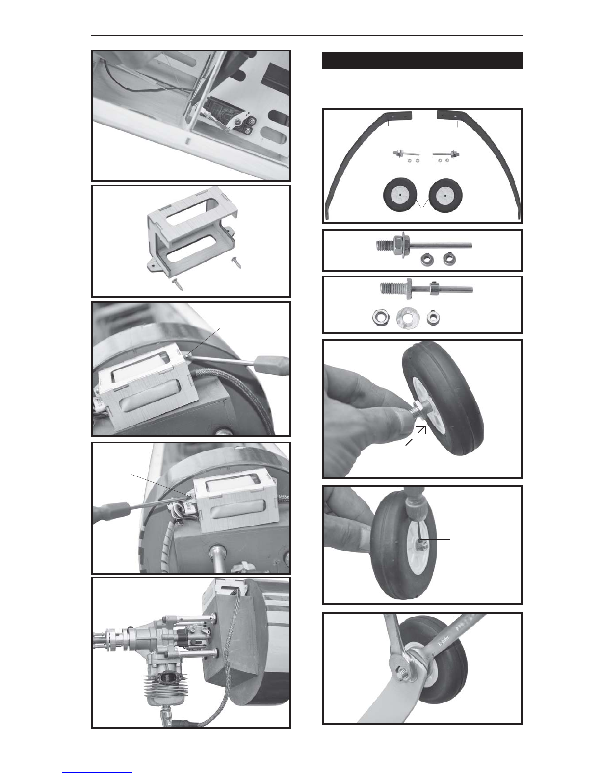
When self-tapping screws have to be
screwed into wood, apply a little white glue
to prevent them shaking loose: just squirt
white glue into the hole and fit the screw.
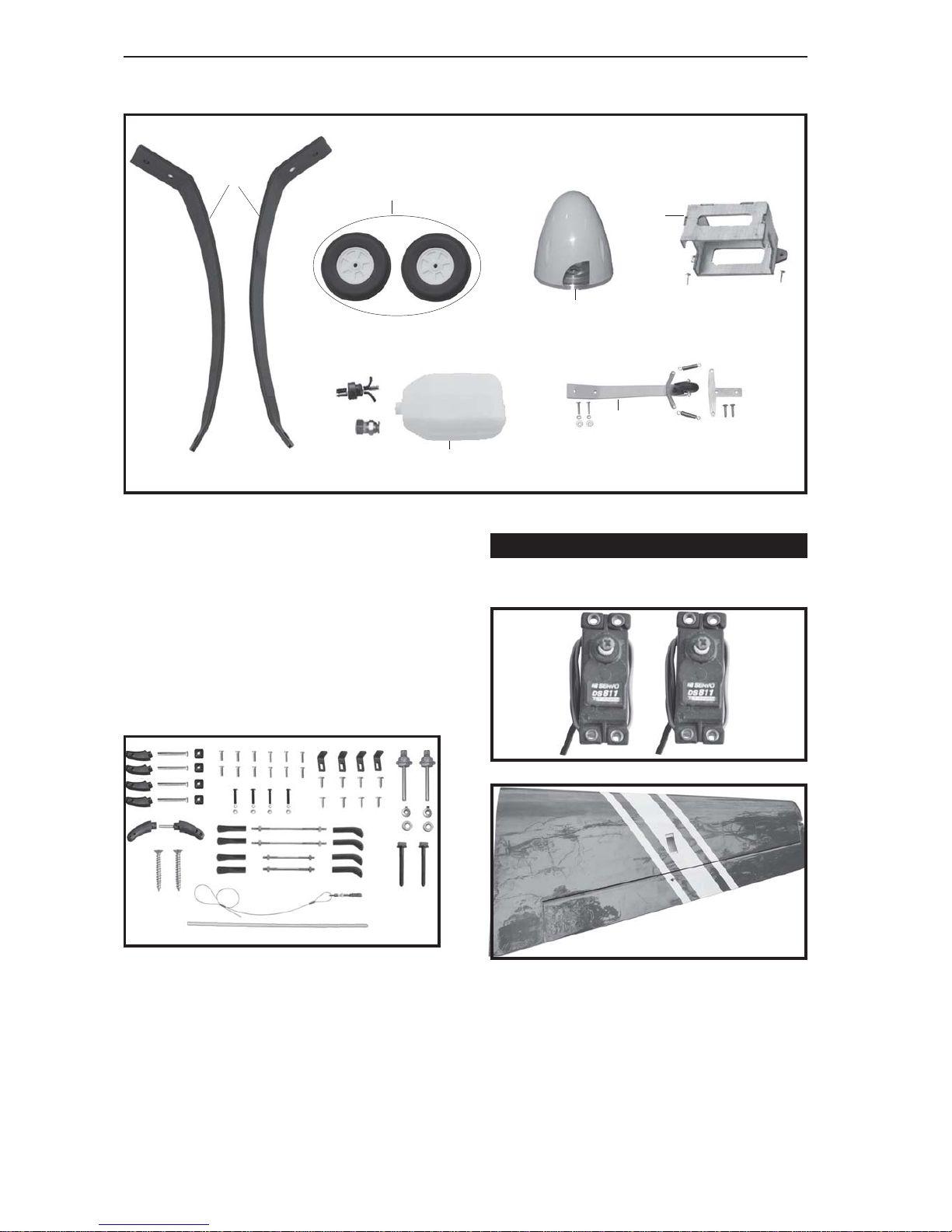
REPLACEMENT LARGE PARTS
+ This is not a toy
+ Be sure that no other flyers are using your
radio frequency.
+The glowplugclipmustbe securelyattached
to the glow plug.
+ Do not flip the propeller with your fingers.
+ Keep loose clothing and wires away from
thepropeller.
+ Do not start the motor if people are near.
Donotstand in line with theside of the propel-
ler.
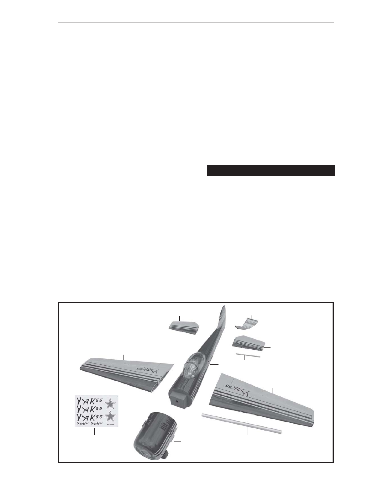
D . Horizon stabilizer.
A.Cowling.
B. Wing panel.
C. Fuselage. G. Decal sheet.
F. Aluminium wing dihedral brace.
E. Vertical stabilizer.
G.
B.
C.
D.
D.
B.
F.
A.
E.
F.

YAK 55 - ITEM CODE:BH111. Instruction Manual
4
1. Install the rubber grommets and brass
eyelets onto the aileron servo.
INSTALLING THEAILERON SERVOS.
REPLACEMENT SMALL PARTS
1. Aluminium landing gear.
3.Spinner.
2. Wheels.
5. Fuel Tank.
Aileron
Bottom side
2)Using a modeling knife, removethecov-
ering at possition show below.
3) Using the thread as a guide and using
masking tape, tape the servo lead to the end
of the thread: carefully pull the thread out.
When you have pulled the servo lead out, re-
move the masking tape and the servo lead
from the thread.
6. Tail gear set.
4.Engine mount ply of wood .
1.
3.
4.
2.
5.
6.

5
YAK 55 - ITEM CODE:BH111. Instruction Manual
Electricwire
Thread
Secure
Repeat the procedure for the other wing
half.
INSTALLING THEAILERON CONTROLHORN
.
Installaileron controlhorn assame as
picturebelow.
3 x 25 mm.
AileronControl
horn.
5. Instal servo tray with aileron servo into
the wing as same as picture below.
4) Drill 1,6mm pilotholes through the block
of wood for each of the four mounting screws
provided with the servo.
Installing the aileron linkages as pictures
below.
3.INSTALLING THE AILERON
LINKAGES.
Secure.
Secure.
55 mm
2x8 mm.
Bottom side
Repeat the procedure for the other wing
half.
Aileron

YAK 55 - ITEM CODE:BH111. Instruction Manual
6
Drill a hole
4mm diameter.
See pictures below:
1. Install one adjustable metal connector
through the third hole out from the center of
one servo arm, enlarge the hole in the servo
arm using a 2mm drill bit to accommodate the
servo connector. Remove the excess mate-
rial from the arm.
After installing the adjustable metal con-
nector apply a small drop of thin C/A to
the bottom nut. This will prevent the con-
nector from loosening during flight.
INSTALLING THE THROTTLE - CABLE.
Throttle servo
Throttle servo
Throttle cable.
INSTALLING THE ENGINE MOUNT.
Secure

7
YAK 55 - ITEM CODE:BH111. Instruction Manual
Secure.
Secure.
Left side.
PARTSREQUIRED
1)Assembleandmountingthewheelpants
as shown in the following pictures.
Secure.
MAIN GEAR INSTALATION.
Engine mount
ply of wood .
3 x 12mm.
Secure.
Landing
gear.
1. 1.
2.

YAK 55 - ITEM CODE:BH111. Instruction Manual
8
2) A drop of C/A glue on the wheel collar
screws will help keep them from coming lose
duringoperation.
Repeat the process for the other wheel.
INSTALLING THE STOPPER ASSEMBLY
1) The stopper has been pre-assembled
at the factory.
2) Using a modeling knife, cut one length
ofsiliconfuel line (the length ofsiliconfuel line
iscalculatedbyhow the weighted clunkshould
restabout8mm away from the rear ofthetank
andmovefreelyinside the tank). Connect one
end of the line to the weighted clunk and the
otherendto the nylon pick uptubein the stop-
per.
3) Carefully bend the second nylon tube
up at a 45 degree angle (using a cigarette
lighter). This tube will be the vent tube to the
muffler.
4) Carefullybendthethirdnylontube down
ata45degreeangle(usingacigarette lighter).
This tubewillbeventtubetothefuelingvalve.
FUEL TANK.
When the stopper assembly is installed in the
tank, the top of the vent tube should rest just
belowthetop surface of thetank. It should not
touch the top of the tank.
5) Test fit the stopper assembly into the
tank. It may be necessary to remove some of
the flashing around the tank opening using
amodelingknife. Ifflashing is present, make
sure none of it falls into the tank.
(Silicon tube not included)
Silicon tube.
Vent tube Fuel pick- up tube
Fuelfill tube
Secure
Bottom side.

9
YAK 55 - ITEM CODE:BH111. Instruction Manual
6) When satisfied with the alignment of
thestopperassemblytighten the3mmx20mm
machine screw until the rubber stopper ex-
pandsandsealsthetankopening.Donotover
tighten the assembly as this could cause the
tank to split.
7) Using a modeling knife, cut 3 lengths of
fuel line 150mm long. Connect 2 lines to the 2
vent tubes and 1 line to the fuel pickup tube in
the stopper.
8) Feed three lines through the fuel tank
compartment and through the pre-drilled hole
in the firewall. Pull the lines out from behind
the engine, while guiding the fuel tank into
place. Push the fuel tank as far forward as
possible,thefrontofthetankshouldjustabout
touch the back of the firewall.
Blow through one of the lines to ensure
the fuel lines have not become kinked inside
the fuel tank compartment. Air should flow
througheasily.
9) To secure the fuel tank in place, apply a
bead of silicon sealer to the forward area of
thetank,whereitexitsthefuselagebehindthe
enginemountingbox andtotherearofthe tank
at the forward bulkhead.
Do not secure the tank into place perma-
nently until after balancing the airplane. You
may need to remove the tank to mount the
battery in the fuel tank compartment
Secure
Tie wrap.
Fueltank
1. Slide the fiberglass cowl over the en-
gineandlineupthebackedgeofthecowlwith
the marks you made on the fuselage.
2. While keeping the back edge of the
cowl flush with the marks, align the front of
thecowlwiththecrankshaft of theengine. The
front of the cowl should be positioned so the
crankshaft is in nearly the middle of the cowl
opening. Hold the cowl firmly in place using
pieces of masking tape.
3. Slide the cowl back over the engine
andsecureitin place using four woodscrews.
See picture below.
Top side.
COWLING.

YAK 55 - ITEM CODE:BH111. Instruction Manual
10
Left side.
Top side
4. Installthemufflerandmufflerextension
onto the engine and make the cutout in the
cowl for muffler clearance. Connect the fuel
and pressure lines to the carburetor, muffler
andfuel filler valve.
Trim and
cut
3x 12mm
Drill a hole
2.5mm diameter.
Drill a hole
2.5mm diameter.
Markpoint
65 mm
Markpoint.
65 mm

11
YAK 55 - ITEM CODE:BH111. Instruction Manual
Secure.
Machinescrew.
Installthespinnerbackplate,propellerand
spinner cone. The spinner cone is held in
place using two 3mm x 12mm wood screws.
Front view.
Secure.
Secure.
Secure.
INSTALLING THE SPINNER.

YAK 55 - ITEM CODE:BH111. Instruction Manual
12
247mm
9 mm
3 x 15mm
Bottom side.
See pictures below:
HORIZONTAL STABILIZER.
3x15mm
Secure
Left side.
Right side.
Aluminium

13
YAK 55 - ITEM CODE:BH111. Instruction Manual
Secure
Rudder servo install as same as method of
elevator servo. See picture below:
VERTICAL INSTALLATION.
Rudder servo
2x8 mm.
130 mm
ELEVATOR CONTROL HORN AND
ELEVATOR PUSHROD INSTALLATION.
3 x 25 mm.
Secure
Elevator
pushrod
Elevator
pushrod
Bottom side.
Secure
Secure
Elevatorcontrol
horn.

YAK 55 - ITEM CODE:BH111. Instruction Manual
14
Rudder control horn install as same as the
way of aileron control horn. Please see pic-
tures below.
ControlhornofRudder.
Rudder servo
Aluminium
A+B PLUS glue
RUDDER CONTROL HORN INSTALLA-
TION.
3 x 35 mm
Cut.
Bottom side.
A+BPLUS
Glue.

15
YAK 55 - ITEM CODE:BH111. Instruction Manual
1. Rudder pushrod install as same as
the way of aileron control horn.
2. Rudder push - pull system install as
same as picture below.
RUDDER CAPLE INSTALLATION.
2 x 8mm
Secure.
Secure.
2 x 8 mm.
Top side.
Secure.
Elevatorpushrod
Elevator
pushrod
Rudder
cable
MOUNTING THE TAIL WHEEL
BRACKET.
3x12mm
3x15mm

YAK 55 - ITEM CODE:BH111. Instruction Manual
16
Switch
Drill 2.5mm
hole.
Secure.
Secure.
Bottom side.
Rudder cable Rudder cable
Elevator
pushrod
Elevator
pushrod
1) Cutouttheswitchholeusingamodeling
knife. Use a 2mm drill bit and drill out the two
mounting holes through the fuselage side.
2) Secure the switch in place using the
two machine screws provided with the radio
system.
INSTALLING THE SWITCH.
Switch

17
YAK 55 - ITEM CODE:BH111. Instruction Manual
Receiver
*** Test fit the aluminium tube dihedral brace
into each wing haft. The brace should slide in
easily. If not, use 220 grit sand around the
edges and ends of the brace until it fits prop-
erly.
Locatethe aluminiumwingdihedralbrace.
WINGATTACHMENT.
25mm
605mm
Battery.
1. Plug the servo leads and the switch
leadintothe receiver. You may want to plug
anaileronextensioninto the receiver to make
plugging in the aileron servo lead easier
when you are installing the wing . Plug the
battery pack lead into the switch.
2. Wrap the receiver and battery pack in
the protective foam to protect them from vi-
bration.Usea rubber band or maskingtape to
hold the foam in place.
3. Position the battery pack and receiver
behindthefueltank.Use twotiewrapstohold
the battery and receiver securely in place as
pictures below
INSTALLINGTHE RECEIVERANDBATTERY.
Tie wrap.
Right wing
See picture wing attach to fuselage.
Wing bolt.
Wing bolt.
Drill a hole
3mm diameter

YAK 55 - ITEM CODE:BH111. Instruction Manual
18
Accurately mark the balance point on the top
of the wing on both sides of the fuselage. The
balancepointislocated 135mm back from the
leadingedge.This isthebalancepointatwhich
yourmodelshouldbalanceforyourfirst flights.
Later, you may wish to experiment by shifting
the balance up to 10mm forward or back to
change the flying characteristics. Moving the
balance forward may improve the smooth-
ness and arrow- like tracking, but it may then
require more speed for take off and make it
moredifficulttoslowdownfor landing. Moving
the balance aft makes the model more agile
with a lighter and snappier ”feel”. In any case,
please start at the location we recommend .
Secure.
Drill a hole
3mm diameter
Top side
Secure.
Left wing
3. Turn the airplane upside down. Place
your fingers on the masking tape and care-
fully lift the plane .
1) It is critical that your airplane be bal-
anced correctly. Improper balance will cause
your plane to lose control and crash.
THE CENTER OF GRAVITY IS LOCATED
135MM BACK FROM THE LEADING EDGE
OF THE WING.
2) Mount the wing to the fuselage. Using a
couple of pieces of masking tape, place them
on the top side of the wing 135 mm back from
the leading edge, at the fuselage sides.
BALANCING.
4 x 40mm
Secure.

19
YAK 55 - ITEM CODE:BH111. Instruction Manual
1. Completely charge your transmitterand
receiver batteries before your first day of fly-
ing.
2. Check every bolt and every glue joint in
your plane to ensure that everything is tight
and well bonded.
3. Double check the balance of the
airplane.
4. Check the control surface.
5. Check the receiver antenna . It should
be fully extended and not coiled up inside the
fuselage.
6. Properly balance the propeller.
PRE-FLIGHT CHECK.
We wish you many safe and enjoy-
able flights with your YAK 55M.
1. Wehighlyrecommendsetting upaplane
using the control throws listed.
2. The control throws should be meas-
ured at the widest point of each control sur-
face.
3. Check to be sure the control surfaces
move in the correct directions.
CONTROL THROWS.
Ailerons : 25 mm up 25mm down
Elevator : 30 mm up 30mm down
Rudder : 35 mm right 35mm left
With the wing attached to the fuselage, all
parts of the model installed ( ready to fly), and
empty fuel tanks, hold the model at the
marked balance point with the stabilizer level.
Lift the model. If the tail drops when you
lift,the model is “tail heavy” and you must add
weigh*tothenose. Ifthenosedrops,itis“nose
heavy” and you must add weight* to the tail to
balance.
Aileron Control
25
25
30
30
35
35
135
Table of contents
Other arf Toy manuals

arf
arf AeroPet 50 User manual

arf
arf SBACH300 20CC V2 User manual

arf
arf SLICK540 120E User manual

arf
arf PITTS 30CC V2 User manual

arf
arf PA-20 Pacer 10e User manual

arf
arf MINIMOA GLIDER User manual

arf
arf BO-209 MONSUN Owner's manual

arf
arf Katana User manual

arf
arf F-6-F User manual

arf
arf CORSAR Owner's manual

arf
arf Composite QQ Yak 54 2.6 m User manual

arf
arf AT.6-TEXAN Owner's manual

arf
arf BH67 User manual

arf
arf MX2 50CC V2 User manual

arf
arf 70 Series User manual

arf
arf P-51 MUSTANG User manual

arf
arf YAK55M 60CC User manual

arf
arf EXTRA300L User manual

arf
arf LITTLE TONI EP User manual

arf
arf AVENSIS Owner's manual