Robe ECOLOR 250 XT User manual


2
Table of contents
1. Safety instructions......................................................................................................... 3
2.Operating determinations .............................................................................................. 4
3.Description of the device ............................................................................................... 5
4.Installation....................................................................................................................... 7
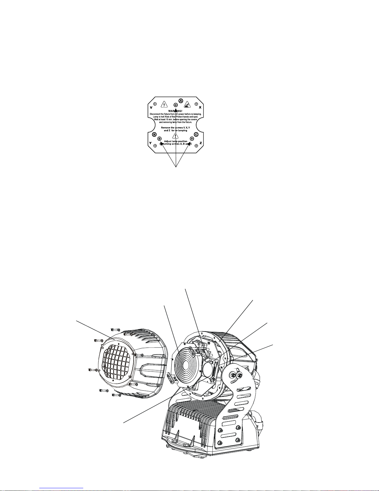
4.1Fitting/Exchanging the lamp....................................................................................... 7
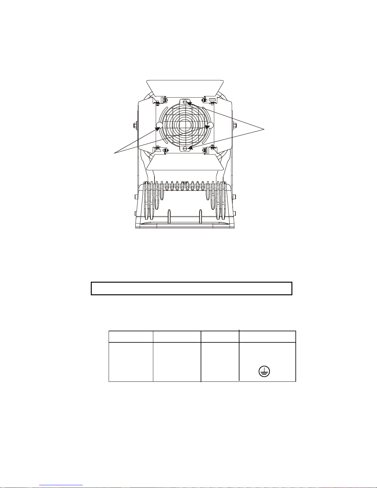
4.2Lamp adjustment........................................................................................................ 7
4.3 Manually adjustment of the effects ............................................................................ 8
4.4 Installation of the barn-doors ..................................................................................... 9
4.5Connection to the mains.............................................................................................9
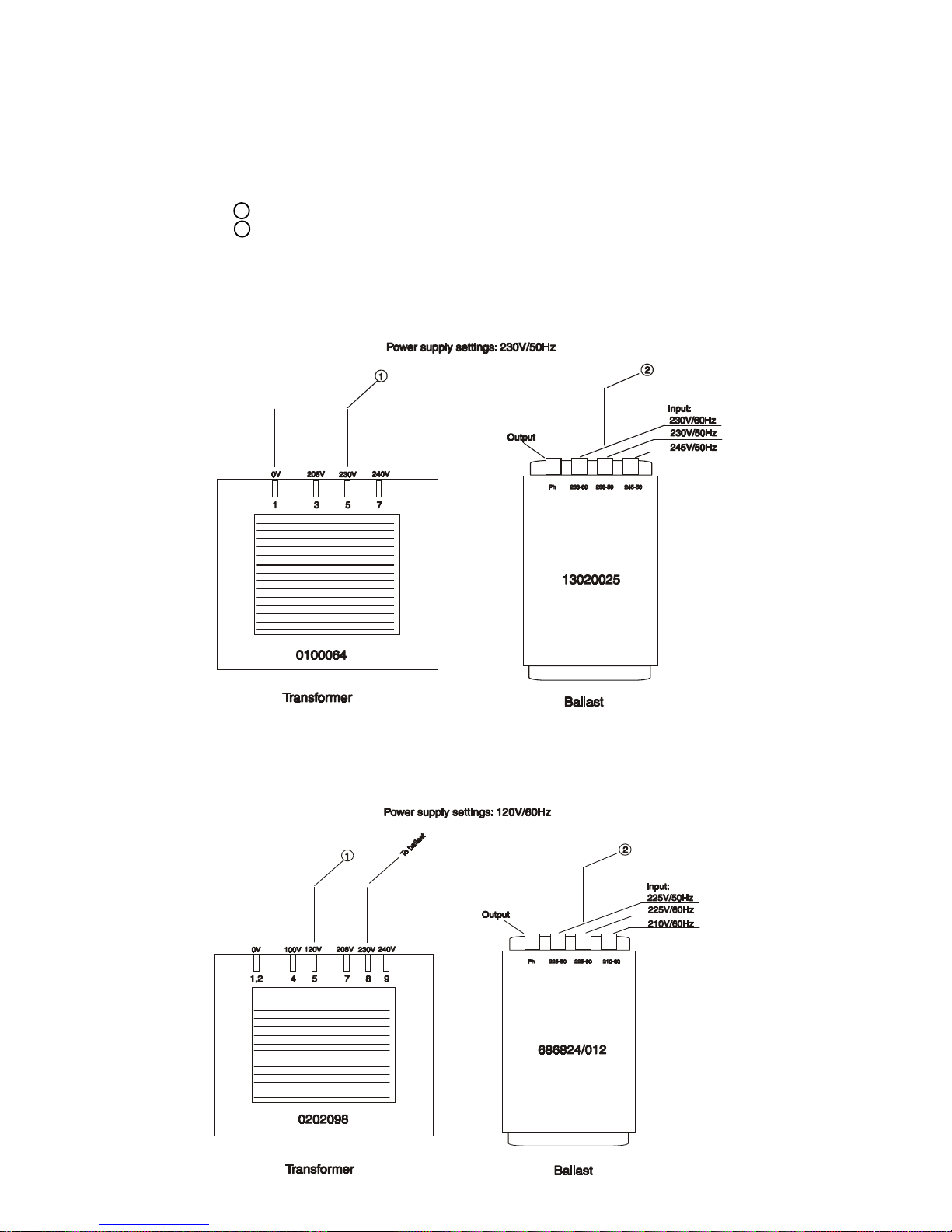
4.6 Changing the power supply settings ....................................................................... 10
4.7 Rigging.................................................................................................................... 11
4.8 DMX- 512 connection, master/slave connection ..................................................... 13
5. DMX PROTOCOL.......................................................................................................... 14
6.Control of the fixture .................................................................................................... 15
7.Controller mode............................................................................................................ 15
7.1 DMX addressing ..................................................................................................... 15
7.2 Remotely and manually controllable functions........................................................ 16
8. Stand - alone mode...................................................................................................... 16
9. Functions of the control panel.................................................................................... 18
9.1 Addressing .............................................................................................................. 18
9.2 Slave control ........................................................................................................... 19
9.3 Fixture informations................................................................................................. 19
9.4 Personality options.................................................................................................. 20
9.5 Switching On/Off the lamp....................................................................................... 23
9.6Test sequences........................................................................................................ 23
9.7 Stand-alone setting ................................................................................................. 24
9.8 Reset function ......................................................................................................... 27
9.9 Special functions..................................................................................................... 28
10. Error and information messages.............................................................................. 30
11.Technical specifications ............................................................................................ 30
12. Maintenance and cleaning ........................................................................................ 32
ECOLOR 250 XT

3
CAUTION!
Keep this device away from rain and moisture!
Unplug mains lead before opening the housing!
FOR YOUR OWN SAFETY, PLEASE READ THIS USER MANUAL CAREFULLY
BEFOREYOU INITIAL START - UP!
1. Safety instructions
Caution ! Be careful with your operations.With a dangerous voltage you can suffer
a dangerous electric shock when touching the wires
Thisdevice has leftourpremises inabsolutelyperfect condition. Inorderto maintain thisconditionand toensure
asafe operation, itisabsolutely necessaryforthe user tofollowthe safety instructionsandwarning noteswritten
in this manual.
Important:
Damages caused by the disregard of this user manual are not subject to warranty.The dealer will not accept
liability for any resulting defects or problems.
If the device has been exposed to drastic temperature fluctuation (e.g. after transportation), do not switch it on
immediately.Thearising condensationwatermightdamage yourdevice.Leavethe deviceswitchedoffuntil it has
reachedroomtemperature.
This device falls under protection-class I.The power plug must only be plugged into a protection class I outlet.
Neverletthe power-cord comeintocontactwith other cables!Handlethepower-cord and allconnectionswiththe
mains with particular caution!
Make sure that the power-cord is never crimped or damaged by sharp edges. Check the device and the power-
cord from time to time.
Always disconnect from the mains, when the device is not in use or before cleaning it.
During the initial start-up some smoke or smell may arise.This is a normal process and does not necessarily
mean that the device is defective.
Caution: Duringthe operation, thehousingbecomes veryhot.
Do not switch the device on and off in short intervals as this would reduce the lamp’s life.
HEALTH HAZARD!
Never look directly into the light source,as sensitive persons may suffer
an epileptic shock
( especially meant for epileptics) !
Please consider that damages caused by manual modifications to the device are not subject to warranty.
Keepawaychildren andamateurs!

4
2.Operating determinations
This device is an architectural luminaire for creating decorative effects and was designed for outdoor use.
Never run the device without lamp!
Do not shake the device.Avoid brute force when installing or operating the device.
Weatherizeddesign to IP65.
Whenchoosing theinstallation-spot,please make surethat the deviceis not exposedto extreme heat,moisture
or dust.There should not be any cables lying around.You endanger your own and the safety of others!
The minimum distance between light-output and the illuminated surface must be more than 1,0 meter.
Make sure that the area below the installation place is blocked when rigging, derigging or servicing the fixture.
The exterior of the fixture becomes very hot,up to 110°C.Do not place the fixture in areas where accidental
contact is likely.
Onlyoperate the fixtureafterhaving checkedthatthe housing isfirmlyclosed and allscrewsare tightlyfastened.
The lamp must never be ignited if the objective-lens or any housing-cover is open, as discharge lamps may
explose and emit a high ultraviolet radiation, which may cause burns.
Themaximum ambienttemperatureta=40°Cmust never beexceeded.
CAUTION!
The lens has to be replaced when it is obviously damaged,
so that its function is impaired, e. g. due to cracks or deep scratches!
Operate the device only after having familiarized with its functions. Do not permit operation by persons not
qualifiedfor operatingthedevice. Most damagesare the resultofunprofessional operation!
CAUTION!
The lamp has to be replaced when it is damaged
or deformed due to the heat!
Please use the original packaging if the device is to be transported.
Please consider that unauthorized modifications on the device are forbidden due to safety reasons!
Never remove the serial barcode from the device as this would make the guarantee void.
If this device will be operated in any way different to the one described in this manual, the product may suffer
damages and the guarantee becomes void. Furthermore, any other operation may lead to dangers like short-
circuit, burns, electric shock, lamp explosion, crash etc.

5
3.Description of the device
1- Front cover of the head
2- Rear cover of the head
3 - Bracket bolts
4 - Head bracket
5 - Base
Front side
Rear side
6 - Lamp cover
7 - Patchcord
8 - DMX input
9 - DMX output
10 -Powercord
11 -Patchcord

6
17 - Red LED
18-Up-button
19-Down-button
20 -Infra-red transmitter
21 -Lamp On-button
22-Mode-button
23 - Blackout/lamp off-button
24 -Enter-button
Display board
12 -Green LED
13 -Red LED
14 -Infra-red transceiver
15 - Light sensor
16 - Display

7
4.Installation
4.1Fitting/Exchanging the lamp
DANGER !
Unplug from mains before !
Allow the lamp to cool for 20 minutes before removing the lamp cover
To insert the lamp MSD 250 open the small cover at the rear of the projection-head (see the drawing ) by
loosening the 4 screws on the cover.Remove the rubber seal.Loose the 4 screws ("V,X,Y,Z") on the lamp
assembly and gently pull the lamp assembly out.If changing the lamp, remove the old lamp from the socket.
Insert the lamp to the socket.
Do not install a lamp with a higher wattage! A lamp like this generates temperatures the device is not designed
for.
Damages caused by non-observance are not subject to warranty.Please follow the lamp manufacturer‘s notes!
Do not touch the glass bulb with bare hands during the installation! Make sure that the lamp is installed tightly
intothe lampholdersystem.
Reinsert the lamp assembly and tighten the 4 screws ("V,X,Y,Z").Close the small lamp cover with the seal by
cross-tighten the 4 fastening screws with a torque of 6-7Nm..
Before striking the lamp, reset the "LAti/rSEt" and "LASt/rSEt"- counter in the "InFO" menu of the fixture, by
pressing the "Up" and "Down" buttons in one time and then confirming with the "Enter"-button on the remote
control.
Do not operate this fixture with opened housing-cover!
4.2Lamp adjustment
The fixture lampholder is aligned at the factory.Due to differences between lamps, fine adjustment may improve
lightperformance.
Open the lamp cover at the rear of the projection-head by loosening the 4 screws on the cover.
Removethe rubber seal.
Lampassembly
Lampcover
Lamp
Rubberseal

8
Strikethe lamp,cancelall effects, set thedimmer intensity onto100 % andfocusthe lightona flatsurface(wall)
or use function "LAAd" in the Special functions .
Adjust the lamp until the light is even using the 3 adjustment screws "A, B, C" on the lamp assembly.Turn one
screw at a time to distribute the light evenly.
To reduce a hot-spot, pull the lamp in by turning all three screws "A, B, C” clockwise 1/4-turn at a time until the
light is evenly distributed.
If the light is brighter around the edge than it is in the center, or if light output is low, the lamp is too far back in the
reflector.„Push”the lamp outbyturning thescrews"A,B,C"counterclockwise1/4-turnat atimethe lightis bright
andevenly distributed.
Close the lamp cover with the seal and cross-tighten the 4 fastening screws with a torque of 6-7 Nm.
4.3 Manually adjustment of the effects
Zoom
Thelenssystem can beconfigured intherangebetween8° and 22°beamangles.To set thedesiredbeamangle,
open the front cover by loosening the 8 screws,remove the rubber seal, loose the 2 adjusting screws on the
fresnel lens unit and adjust the required beam angle.Tighten the adjusting screws again and fix the front cover
with the rubber seal.Cross-tighten all screws with a torque of 6-7 Nm.
Beam shapers,frost filter,colour temperature correction filter 3200K
Open the front cover by loosening the 8 screws,remove the rubber seal.Loosen the 2 adjusting screws on the
desired module and set the suitable effect (vertical and horizontal beam shaper,frost filter, 3200K temperature
filter).Tightentheadjusting screws againandfixthe front coverwiththerubberseal back.Cross-tighten allscrews
with a torque of 6-7 Nm.
Screws "A,B,C"
Fresnel lens
Front cover
Rubberseal
Adjusting screw
for fresnel unit
Adjusting screw for
correctionfilters module
Beamshapermodule
Correctionfiltermodule

9
4.4 Installation of the barn-doors
You can install the barn-doors to better define the iluminated surface.The barn-doors are fixed with the 2 screws
andmaybeturned inrange90°.The barn-doors are notincluded in standarddelivery.
adjusting screws
fastening screws
4.5Connection to the mains
Verify the power supply settings before applying power!
If you wish to change the power supply settings,see next chapter.
Connectthe fixturetothe mainswiththe protected andweatherproof power plug.
The earth has to be connected!
The occupation of the connection-cables is as follows:
Cable (EU) Cable (US) Pin International
Brown Black Live L
Lightblue White Neutral N
Yellow/Green Green Earth

10
4.6 Changing the power supply settings
Both the transformer and the ballast must be connected correctly for the local AC voltage and frequency.
Thewrong settingscancause poor performanceor demage ofthe moving head.Thefactory settings areprinted
on the bottom of the base.
If you want to change the power supply settings,follow the instructions:
1.Disconnect the fixture from AC power.
2.Open the plate cover of the base by loosening the 12 screws and remove the rubber seal.
3.Move the wire 1 on the transformer connection block to the position according to the desired voltage.
4.Move the wire 2 on the ballast connection block to the position according to the desired frequency
(voltage).
5.Closethe base before applyingACpower.To ensure a weather-tight seal when replacing the plate cover of
the base,carefully cross-tighten all screws with a torque of 6-7 Nm.
Examples: EU-version
US-version

11
4.7 Rigging
DANGERTO LIFE!
Please consider the respective national norms during the installation! The
installation must only be carried out by an authorized dealer!
Theinstallationof the fixturehastobe built andconstructedina way thatitcanhold 10 timestheweightfor 1 hour
withoutanyharming deformation.
Whenrigging, derigging orservicingthe fixturestayingin the areabelowthe installationplace,on bridges, under
highworking places andotherendangeredareas is forbidden.
Theoperatorhas tomakesurethat safety-relating andmachine-technicalinstallationsare approvedbyan expert
before taking into operation for the first time and after changes before taking into operation another time.
Theoperator hastomake sure thatsafety-relating and machine-technicalinstallationsare approvedbya skilled
persononce ayear.
The fixture should be installed outside areas where persons may walk by or be seated.
IMPORTANT! OVERHEAD RIGGING REQUIRES EXTENSIVE EXPERIENCE, including (but not limited to)
calculating working load limits, installation material being used, and periodic safety inspection of all installation
material and the fixture. If you lack these qualifications, do not attempt the installation yourself, but instead use
a professional structural rigger.Improper installation can result in bodily injury and or damage to property.
The fixture has to be installed out of the reach of people.
If the fixture shall be lowered from the ceiling or high joists, professional trussing systems have to be used.The
projector must never be fixed swinging freely on the mounting place.
Caution: Fixturesmay cause severeinjuries when crashingdown!If you havedoubts concerning thesafetyof a
possible installation, do NOT install the projector!
The fixture can stand directly on the floor by standing on the 2 removable stands which are mounted with the 4
bolts M10 to the fixture's base.If you demount this stands,the fixture's base enables the fixture to be mounted
with the screws M10 through the 12 mm slot to the desired site.
fixture's base: removable stand:

12
Danger of fire !
When installing the device, make sure there is no highly inflammable
material (decoration articles, etc.) in between a distance of min. 1,0 m.
CAUTION!
Follow the instructions mentioned at the bottom of the base.
Make sure that the device is fixed properly! Ensure that
the structure (truss) to which you are attaching the fixtures is secure.
Before rigging make sure that the installation area can hold a minimum point load of 10 times the projector’s
weight.
Install the fixture away from accidental public contact.
The fixture is rated to IP65 and may be mounted in any orientation without altering its operation characteristics
(see the drawing).The fixture's head can be adjusted in a vertical range 130°.
Allow the fixture to cool before handling!
DANGERTO LIFE!
Before taking into operation for the first time,the installation has to be
approved by an expert!

13
4.8 DMX- 512 connection, master/slave connection
The wires must not come into contact with each other,otherwise
the fixtures will not work at all,or will not work properly.
Onlyuse aRS-485data cable and3-pin XLR connectorsin order toconnect the controllerwiththe fixtureorone
fixturewith another.Theconnectors mustbeprotectedin aweatherproofhousing.
Occupation of the XLR-connection:
DMX - output DMX-input
XLR mounting-socket: XLR mounting-plug:
Building a serial DMX-chain:
Ifyou are usingthestandard controllers, youcanconnect the DMX-outputofthe controller directlywiththe DMX-
input of the first fixture in the DMX-chain. If you wish to connect DMX-controllers with other XLR-outputs, you
needto use adapter-cables.
Connect the DMX-output of the first fixture in the DMX-chain with the DMX-input of the next fixture. Always
connect output with the input of the next fixture until all fixtures are connected.
Caution: At the last fixture, the DMX-cable has to be terminated with a terminator.A termination plug is an XLR
connector with a 120 ohm resistor soldered across pins (+) and (–).
Building a master/slave-chain:
Connect the DMX-output of the master fixture in the data-chain with the DMX-input of the first slave. Always
connect output with the input of the next slave until all slaves are connected (up to 9 fixtures).
Caution:It’snecessary toinsert theXLR termination plug(with120 Ohm)intothe input ofthe master fixtureand
into the output of the last slave fixture in the link in order to ensure proper transmission on the data link.
Master/slave operation
Controller operation
1-Ground
2 - Signal (-)
3 - Signal (+)
1-Ground
2 - Signal (-)
3 - Signal (+)

14
5. DMX PROTOCOL
Channel Value Function Type of control
1 Cyan
0-255 Cyan from 0 (white) to 255 (full cyan) proportional
2 Magenta
0-255 Magenta from0(white) to 255(full magenta) proportional
3 Yellow
0-255 Yellow from 0 (white) to 255 (full yellow) proportional
4 Dimmer intensity
0-255 Intensity from 0 to 100% proportional
5 Speed of CMY and dimmer
0-255 From max.speed to min.speed proportional
6 Colour macros,Lamp On/Off,Reset
0-7 Off step
8-15 Macro1 step
16-23 Macro 2 step
24-31 Macro 3 step
32-39 Macro 4 step
40-47 Macro 5 step
48-55 Macro 6 step
56-63 Macro 7 step
64-71 Macro 8 step
72-79 Macro 9 step
80-87 Macro10 step
88-95 Macro11 step
96-103 Macro 12 step
104-111 Macro13 step
112-119 Macro14 step
120-127 Macro15 step
128-139 Lamp On after 3 sec.,reset step
140-229 No function step
230-239 Lamp Off after 3 sec step
240-255 No function step

6.Control of the fixture
TheECOLOR 250 XTiscontroledby infra-red 6-buttonsremote controland 4-digit LED display ontherearside
ofthe fixture. You can simplysetthe lightingaddress,operatingmode,read thenumberof the lamporunit hours,
switch On and Off the lamp, run programs, make a reset and also use special functions for manual and service
purposes.
Two LEDs on the rear panel display the fixture status. Red LED indicates normal operation after switching the
fixture on.Green LED indicates the lamp is switched on.
The red LED on the remote control indicates if any button is pressed (the signal is transmited).
There are the 2 buttons on the remote control which have a special function:[Power]-button and [Blackout/lamp
Off]-button.
The ECOLOR 250 XT can be operated with a controller in controller mode or without the controller in stand-
alone mode.
Both modes are described in the texts below.
7.Controller mode
Thefixturesareindividuallyaddressed(001-507)onadatalinkand connectedtothecontroller.Thefixtures respond
tothe DMX signalfromthe controller.
7.1 DMX addressing
The remotecontrolallows you toassigntheDMX fixture address,whichisdefinedas the firstchannelfromwhich
theECOLOR 250 XTwillrespond to thecontroller.
If you set, for example, the address to channel 5, the ECOLOR 250 XT will use the channel 5 to 10 for control.
Please,be sure thatyoudon’t have anyoverlappingchannels in ordertocontroleach ECOLOR250XTcorrectly
and independently from any other fixture on the DMX data link.
If two, three or more ECOLOR 250 XT are addressed similarly, theywill work similarly.
Foraddress setting,pleaserefer to theinstructions under "Addressing"(menu"A001").
GreenLED
RedLED
Blackout/lamp Off- brief press makes the blackout
- long press makes the lamp Off
Power- switching the lamp On
RedLED

16
Controlling:
After having addressed all ECOLOR 250 XT , you may now start operating these via your lighting controller.
Note:After switching on, the ECOLOR 250 XT will automatically detect whether DMX 512 data is received or
not.If there is no data received at the DMX-input, the display will start to flash "A001" with actually set address.
This situation can occur if:
-the 3PIN XLRplug (cable withDMX signalfrom controller) isnot connectedwith the inputof theECOLOR 250
XT
- the controller is switched off or defective, the cable or connector is defective or the signal wires are swap in the
inputconnector.
Note:It’s necessary to insert the XLR termination plug (with 120 Ohm) to the last fixture in the link in order to
ensure proper transmission on the DMX data link.
7.2 Remotely and manually controllable functions
Lamp
The ECOLOR 250 XT is to be operated with a MSD/HSD 250 or MSD 250/2 lamp.
Arelay insideofthe ECOLOR250XT allowsyouto switchonand offthelamp viatheremote control orviayour
DMX-controller without affecting the rest of the lighting.
To switchOn/Offthe lamp,usethe[Power]-buttonor [Blackout/lamp Off]-buttononthe remote control.Youcan
use also menu "LAMP"- please refer to "Switching On/Off the lamp ".
Note: It is also important to note, that the discharge lamp is cold restrike types, that means, that they have to be
coldbefore re-striking. Forthisreason, you havetowait5 minutes(afterhavingswitched Offthelampbefore you
can switch it back On again. If you try to switch On the lamp within 5 minutes after having switched it Off, the
ECOLOR 250 XT will store this information and automatically ignite the lamp when the 5 minutes period has
expired.The message "HEAt" will appear on the control board display of the ECOLOR 250 XT. If the ignition of
the lamp is seven times unsuccessful, on the display will appear "LA.Er.", meaning that the lamp could be
damaged or even missed, or there could be a failure on the ignitor or ballast.
Avoid turning on several lamps at once.
CMY-colors mixing system
The CMY color mixing system is based on graduated cyan,magenta and yellow color filters.A continuous range
of colours may be achived by varying the amount of each filter from 0 to 100%
Dimmer
Smooth 0-100% dimming is provided by the special dimmer unit.
Beam effects
Horizontal and vertical beam shapers – manually adjustable.Frost filter for softer beam and colour temperature
correctionfilter 3200K–manually adjustable.
Clock
The ECOLOR 250 XT has a battery operated 24-hour clock that can set the start and the stop stand-alone
operation.
Cooling
The ECOLOR 250 XT is cooled by one axial fan in the head.
8. Stand - alone mode
The fixtures on a data link are not connected to the controller but can execute pre-set programs which can be
different for every fixture.To set the program to be played,see the "Stand-alone setting" ( menu "St.AL.").
"Stand-aloneoperation" can beappliedto the single fixture(thefixture maybesetto themaster/slavemode )or
to multiple fixtures operating synchronously.
Synchronous operation of multiple fixtures requires that they must be connected on a data link and one of them
is set as a master (master mode) and the rest as the slaves (slave mode).The slaves are assigned to SLA.1-
SLA.9 and on the certain slave address can be connected only one fixture.To set the fixture as the master or
slave , see the "Addressing" (menu "A001").
If the master fixture runs a reset,switches On/Off the lamp or plays test(program) ,all slaves will execute
these acts too (e.g. if the master fixture has switched its lamp off,no slave can switch its lamp on)!
You can't play or edit any programs on the slaves by their control displays if the master is switched on
and connected to the master/slave chain.

17
The master fixture starts simultaneous program start in the other slave fixtures.All fixtures have a definite,
synchronized starting point when playing back their programs.The number of running program is the same in all
slaves and depends on the master's choice (menu "St.AL." ).Every fixture runs its program repeatedly ,starting
the program step No.1 when requested by the master .
Forexample:
If the slave fixture has a shorter program length, it will continously repeat its program until the master fixture
finishes its own program and restarts its program running (slave 1- prog.step 3 will not be finished).
If the slave fixture has a longer program length, it will restart at prog.step 1 before it completes all its prog.steps
(slave 2 - prog.step 5 will not be played)- see the picture bellow.
Stand-aloneoperationcanbesetfor one or twoperiods duringa 24hour period,usingthebuilt-inclockorforalight
level,using the built-in light sensor.If both the clock and the light sensor are active, operation starts within the set
times or if it is darker than the light-level setting.Operation stops at the stop times or if that the ambient light is
brighter than the set light level.
If the time periods overlap each other or if the time period overlaps the light level period,the fixture will respond
to the events according to their rank.
Forexample:
The played program is the same for all time(light level) periods.
From the master's control panel is possible to control any slave in a master/slave chain.
Note:Disconectthe fixtures fromtheDMXcontroller before master/slaveoperating,otherwisedata collisions can
occur and the fixtures will not work properly!
Note:It’s necessary toinsert the XLRtermination plug(with120 Ohm)intotheinput ofthemaster fixture andinto
the output of the last slave fixture in the data link in order to ensure proper transmission on the data link.
Starting point
Restart
All events will be executed
(Start1,Stop1,Start2,Stop2).
The events Start 1 and Stop 2
will be executed only.
The events Start 1 and Stop
will be executed only.
The Time period1 and Light
period will be executed ,the
Time period 2 is eliminated.

18
9. Functions of the control panel
The control panel situated on the front side of the base offers several features.You can simply set the DMX
address,master/slave mode, read the number of lamp or unit hours, run test, make a reset and also use many
functions for setting and service purposes.
The main menu of the control panel is accessed by pressing the [ Mode ] button - press this one so many times
untilthedisplayshows message "A001" (withactuallystoredaddress).Browsethrough the menu bythepressing
[ Up ] or [ Down ] buttons - the display shows step by step these messages: A001,SLCt, InFO,PErS,tESt,
StAL,rESE,SPEC.Press [ Enter ] if you wish to select one of them.The functions are described in the following
sections and the function hierarchy is shown below.
9.1 Addressing
By this menu you can set the DMX address or address the fixture as a master/slave.
- DMX addressing
1.Pressthe[Mode]- buttonsomanytimesuntil the display shows message "A001" (withactually storedaddress).
2.Press [Enter]-buttonand use the[Up] and[down] buttons toselect"dM.Ad."-menu.
3.Press[Enter]-button(the letter"A"flashes) and by[Up]and[down] buttons selectrequiredaddress (001-
507), press [Enter]-button to confirm.
4.Select"MA.SL."-menu,press[Enter]-button and use[Up] and[down] buttonstoselect "d.AbL."(nomasteror
slave),press [Enter] to confirm.
5.Press the [Mode]- button.Choosen address is shown on the display.
If message "A001" (with actually stored address) flashes-no DMX data received at the DMX-input.
- Master/slave adressing
1. Press the [Mode] button so many times until the display shows message "A001" (with actually stored
address).
2. Press [Enter]-button and use the [Up] and [down] buttons to select "MA.SL."-menu.
3. Press[Enter]-button(display flashes) and select"MASt."(to set the fixture as the master in a chain of multiple
fixtures) or "SLA.1"-"SLA.9" (tosetthe fixturetobe theslavein a chainof multiple fixtures)andpress [Enter]
to confirm. If you want address no master or slave, select "d.AbL.".
4.Press the [Mode]- button.Chosen address is shown on the display.
If message "MASt." fast flashes- DMX signal is received at the DMX-input.Disconnect DMX controller!
Only one fixture may be the master. Up to the 9 slaves may be connected to the master and on the certain
address can be connected only one slave fixture (SLA.1-SLA.9).

19
Note:Disconectthe fixtures fromtheDMXcontroller before master/slaveoperating,otherwisedata collisions can
occur and the fixtures will not work properly!
If the fixture is set as the master and DMX signal is connected to its input,the error massage "MAEr" will appear
onits displayand thefixture'saddress willbe settoits DMX addressin ordertorespond toDMX signalfromthe
controller.
Forexample:
The master fixture has this address setting:"dM.Ad."-menu.........A013
"MA.SL."-menu........MASt (is displayed)
The DMX signal is connected to the master fixture.The message "MAst" starts fast flashing and after 20s error
massage "MA.Er" appears on its display and the fixture automatically will be switched to its DMX address
(masteraddress isdisabled).
Now the fixture has the address setting: "dM.Ad."-menu.........A013 ("A013"/" MA.Er"blinks )
"MA.SL."-menu.........d.AbL.
If the fixture is set as the slave and DMX signal is connected to its input,the fixture will respond to DMX signal
fromthe controller(independence on thefixture's DMX address).
9.2 Slave control
This function allows you to control the slaves from the master's control panel in a master/slave operation.
Select this function from the main menu and press [ Enter ]-button.Browse the list of all connected slaves
("SL.C.1" - "SL.C.9") by pressing [ Up ] and [ Down ] bottons.Select the desired slave and press [ Enter ]-
button.The slave's control panel is available from the master's control panel.
If no slave is connected to the master,massages "SL.C.1","SL.C.2","SL.C3"..."SL.C.9" still round repeat.
Note:This function is available from the master fixture only.
9.3 Fixture informations
The menu allows you to read an useful information about the fixture as the lamp life,lamp strikes,software
version, etc.
Press[ Up ] or [ Down ] buttons toselectthedesired option andpress[ Enter ] toseethevalue or nextsubmenu.
Power On time
-By this option you can read the total number of the operation hours since the
ECOLOR 250 XT has been fabricated. Press [ Enter ] or [ Mode ] to return to the

20
menu.
-The number of the hours that the ECOLOR 250 XT has been powered On since
the counter was last reset.Press [ Enter ] or [ Mode ] to return to the menu.In order
toresetthis counterto0,youhave toholdthe[ Up ] and [ Down ]-button and pressthe
[Enter]-button.
Lamp On time
-This option enables you to read the total number of the operation hours with the lamp
onsince theECOLOR 250 XThasbeenfabricated.Press[Enter ] or [ Mode ] toreturn
to the menu.
-The number of hours that the lamp has been powered On since the counter was last
reset.Press[Enter] or [Mode] toreturnto the menu.Inorder toresetthis counter to0,
you have to hold the [ Up ] and [ Down ]-button and press the [ Enter ]-button.
Lamp strikes
- By this option you can read the total number of the lamp strikes since the
ECOLOR250 XT hasbeenfabricated.Press [Enter ] or [Mode ] toreturnto the menu.
-The number of the lamp strikes since the counter was last reset.Press [ Enter]
or [ Mode ] to return to the menu. In order to reset the counter to 0, you have to
hold the [ Up ] and [ Down ]-button and press the [ Enter ]-button.
- DMX values
ReadoutDMXvalues of eachchannelreceivedbythe fixture. Usethe[ Up ] and[Down] buttonstoselect desired
channel and press [ Enter ] to read its value coming to the fixture or [ Mode ] to cancel and return to the menu.
- Software version
By this function you can read the software version of the display module. Press [ Enter ] to read its value or [
Mode ] to return to the menu.
9.4 Personality options
These options allow you to modify ECOLOR 250 XT operating behavior.
Press [ Up ] or [ Down ]buttons to select the desired option and press [ Enter ] to set the value or to see next
Table of contents
Other Robe Home Lighting manuals