Robe Robin CycPix 12 User manual

Version 1.3

CycPix 12
2
Table of contents
1. Safety instructions ...................................................................................................................................................... 3
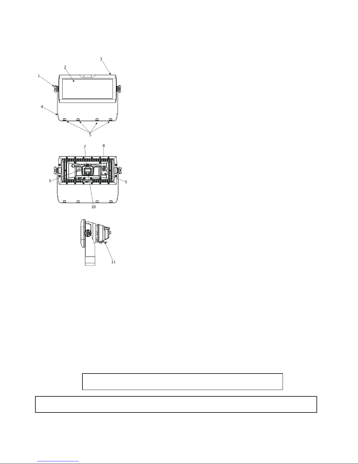
2. Fixture exterior view ................................................................................................................................................... 5
3. Installation .................................................................................................................................................................. 5
3.1 Rigging the fixture ................................................................................................................................................. 5
3.2 Connection to the ains ...................................................................................................................................... 7
3.3 DMX 512 connection ............................................................................................................................................ 7
3.4 Wireless DMX operation ....................................................................................................................................... 8
4. Robin CycPix 12 - DMX protocol ................................................................................................................................. 9
5. Control enu ap .................................................................................................................................................... 16
6. Control enu ............................................................................................................................................................ 19
6.1 Addressing (DMXA) ............................................................................................................................................. 19
6.2 Fixture infor ation (Info) ................................................................................................................................... 19
6.3 Personality (Pers) ................................................................................................................................................ 20
6.4 Manual Control (Manual) ................................................................................................................................... 20
6.5 Test progra (Test Prg) ...................................................................................................................................... 21
6.6 Stand-alone (St Alone) ........................................................................................................................................ 21
6.7 Reset ................................................................................................................................................................... 21
6.8 Special functions (Special) .................................................................................................................................. 22
7. RDM .......................................................................................................................................................................... 23
8. Technical specifications ............................................................................................................................................ 24
9. Cleaning and aintenance ....................................................................................................................................... 28
9.1 Replacing a fuse .................................................................................................................................................. 28
9.2 Disposing of the product .................................................................................................................................... 28

CycPix 12
3
FOR YOUR OWN SAFETY, PLEASE READ THIS USER MANUAL CAREFULLY
BEFORE POWERING OR INSTALLING YOUR Robin CycPix 12
Save it for future reference.
This device has left our pre ises in absolutely perfect condition. In order to aintain this condition and to ensure a
safe operation, it is absolutely necessary for the user to follow the safety instructions and warning notes written in
this anual.
The anufacturer will not accept liability for any resulting da ages caused by the non-observance of this anual
or any unauthorized odification to the device.
Please consider that da ages caused by anual odifications to the device are not subject to warranty.
This device is for professional use only. It is not for household use.
1. Safety instructions
DANGEROUS VOLTAGE CONSTITUTING A RISK OF ELECTRIC SHOCK IS PRESENT WITHIN THIS UNIT
Make sure that the available voltage is not higher than stated on the rear side of the fixture.
This fixture should be operated only fro the type of power source indicated on the arking label. If you are not
sure of the type of power supplied, consult your authorized distributor or local power co pany.
WARNING! The unit does not contain an ON/OFF switch. Always disconnect power input cable to co pletely
re ove power fro unit when not in use or before cleaning or servicing the unit.
Do not overload wall outlets and extension cords as this can result in fire or electric shock.
Make sure that the power cord is never cri ped or da aged by sharp edges. Check the fixture and the power cord
fro ti e to ti e.
Do not install the unit near naked fla es.
Refer servicing to qualified service personnel.
This fixture falls under protection class I. Therefore this fixture has to be connected to a mains socket outlet with
a protective earthing connection.
Do not connect this fixture to a di er pack.
Warning Risk Group 2 LED product according to EN 62471
LED light emission. Risk of eye injury.Do not look straight at the fixture´s LEDs during operation. The intense
light beam may damage your eyes. The light source contains blue LEDs.
Keep co pustible aterials away fro the fixture.
If the fixture has been exposed to drastic te perature fluctuation (e.g. after transportation), do not switch it on
i ediately. The arising condensation water ight da age your device. Leave the device switched off until it has
reached roo te perature.

CycPix 12
4
Avoid brute force when installing or operating the fixture.
This device is for professional use only. It is not for household use.
When choosing the installation spot, please ake sure that the fixture is not exposed to extre e heat or dust.
Avoid using the unit in locations subject to possible i pacts.
Only operate the fixture after having checked that the housing is fir ly closed and all screws are tightly fastened.
Make sure that the area below the installation place is blocked when rigging, derigging or servicing the fixture.
Do not block the front covering glass with any object when the fixture is under operation.
The fixture body never ust be covered with cloth or other aterials.
Always fix the fixture with an appropriate safety cable. Fix the safety cable at the anchor point.
The fixture beco es very hot during operation. Allow the fixture to cool approxi ately 30 inutes prior to
anipulate with it.
Operate the fixture only after having fa iliarized with its functions. Do not per it operation by persons not
qualified for operating the fixture. Most da ages are the result of unprofessional operation!
Do not atte pt to dis antle or odify the unit.
Please consider that unauthorized odifications on the fixture are forbidden due to safety reasons!
Please use the original packaging if the fixture is to be transported.
If this device will be operated in any way different to the one described in this anual, the product ay suffer
da ages and the guarantee beco es void. Further ore, any other operation ay lead to dangers like short-
circuit, burns, electric shock etc.

CycPix 12
5
2. Fixture exterior view
3. Installation
3.1 Rigging the fixture
The Robin CycPix 12 can be rigged in any orientation on a truss without altering its operation characteristics.
For overhead use, always install a safety cable that can hold at least 10 ti es the weight of the fixture. You ust
only use safety cable with screw-on carbine. Use the safety wire anchor point for safety cable attach ent for this
fixture.
Ensure that the structure (truss) to which you are attaching
the fixture is secure.
For overhead installation, the fixture must be always secured with a safety wire that can bear at least 10 times
the wight of the fixture
Fixture ay cause severe injuries when crashing down! If you have doubts concerning the safety of a possible
installation, do not install the device and consult installation with an expert.
1.
Head locks
2. LED zone
3. Head
4. Bracket
5. Sockets for ¼- turn locks
6. DMX IN
/Out
7. Display
8. Power OUT
9. Power IN
10. Control buttons
11. Anchor point for safety cable

CycPix 12
6
Truss installation
1. Bolt cla p (1) to the o ega holder (2) with M12 bolt and lock nut through the hole in the o ega holder.
2. Fasten the o ega holder to the bracket of the CycPix 12 by inserting both ¼ turn quick locks (3) into
the holes of the bracket and tighten fully clockwise.
3. Cla p the fixture on a truss (5) and tighten the rigging cla ps.
4. Pull a safety wire (4) around the truss (5) and lock the screw-on carabine through attach ent point (6) as shown
on the picture below.
.
1- Cla p 4- safety wire
2- O ega holder 5- truss
3- ¼ turn quick locks 6- attach ent point
For a floor installation, you can use a stand with ¼ turn quick locks. Please, keep correct position of the fixture
towards the stand to ensure sufficient stability of the co position fixture-stand.

CycPix 12
7
3.2 Connection to the mains
Fixtures must be installed by a qualified electrician in accordance with all national
and local electrical and construction codes and regulations.
If you install a cord cap on the power cable to allow connection to power outlets, install a grounding-type (earthed)
plug, following the plug anufacturer’s instructions.
The cores in the power cable are coloured according to the following table
.
C
ore
(Eu)
C
ore
(U )
Connection
Plug Terminal Marking
Brown
Black
Live
L
Light blue
White
Neutral
N
Yellow/Green Green Earth , GND, PE
This device falls under class one and must be grounded!
Design of the Robin CycPix 12 allows to connect several fixtures to AC ains power in one interconnected daisy
chain using power input and throughput connectors. Needed daisy chain cords are stated in the chapter
“Technical specifications “
The ax. nu ber of connected fixtures depends on the AC ains power voltage and fixture version:
EU version (CE) US version (cETLus)
21 fixtures at power supply= 230V 12 fixtures at power supply= 230V
19 fixtures at power supply= 208V 11 fixtures at power supply= 208V
11 fixtures at power supply= 120V 6 fixtures at power supply= 120V
Actual nu bers of fixtures ay differ fro values stated above as you have to take into account the length of
supply cables, circuit breaker etc. at projecting of the fixtures installation.
Do not overload the supply line and the connecting leads.
Wiring and connection work ust be carried out by qualified staff!
3.3 MX 512 connection
The fixture is equipped with 3-pin and 5-pin XLR connectors for DMX input/output.
Only use a shielded twisted-
pair cable designed for RS-485 and 3-pin/5-pin XLR- connectors in order to connect the controller with the fixture
or one fixture with another.
Wiring of the XLR connectors:
DMX input DMX output
XLR socket: XLR plug
1– Shield 2 - Signal (-) 3- Signal (+) 4– Not connected 5– Not connected
To build a DMX chain
1. Connect the DMX output of the controller directly with the DMX input of the first fixture in the DMX chain.
2. Connect the DMX output of the first fixture in the DMX chain with the DMX input of the next fixture.
3. Always connect the DMX output with the input of the next fixture until all fixtures are connected.
Do not overload the link. Max. 32 fixtures ay be connected on a DMX link.

CycPix 12
8
Warning for outdoor operation!
Fixture´s XLR connectors are dust and water protected according to IP 65 by ating with related X-HD cable
connectors.
They cannot stay disconnected outdoor. DMX output connector (XLR fe ale) at the last fixture in a DMX line has to
be covered with the rubber cap before inserting a ter inator. The rubber cap does not supply the ter inator. The
XLR ter inator ( ale) has to be dust and water protected.
If the fixture is to be outdoor without connecting to DMX line, always interconnect its DMX input with DMX output
to keep declared IP rating of XLR connectors.
Caution: Ter inate the link by installing a ter ination plug in the output of the last fixture. The ter ination plug is
a 5-pin XLR ale plug with a 120 Oh resistor soldered between Signal (–) and Signal (+).
3.4 Wireless MX operation
The wireless version of the Robin CycPix 12 (Robin CycPix 12/W) is equipped with the Lu en Radio CRMX odule
and antenna for receiving DMX signal. CRMX odule operates on the 2.4 GHz band.
1. Select wireless DMX input fro the enu PEr (PErS-->dMX In.-->Wireless).
2. To link the fixture with DMX trans itter.
The fixture can be only linked with the trans itter by running the link procedure at DMX trans itter .
After linking , the level of DMX signal ( 0-100 %) is displayed in the enu
ite “ tat“ (Special -->Wireless--> Stat).
3. To unlink the fixture fro DMX trans itter.
The fixture can be unlinked fro receiver via the enu ite “Unlink“ (Special-->Wireless-->Unlink).

CycPix 12
9
4. Robin CycPix 12 - MX protocol
Version 1.1
Mode 1 - Standard 16 bit, Mode 2 - Reduced 8 bit, Mode 3 - Extended 16bit +RGB pixels,
Mode 4 - Extended 16bit + RGBD pixels
Mode/Channel
Value Function Type of
control
1 2 3 4
1 1 1 1
0-19
20-24
25-29
30-39
40-49
50-59
60-69
70-89
90-99
100-109
110-119
120-129
130-179
180-189
190-255
pecial functions
Reserved
To activate following functions , stop in DMX value
for at least 3 sec. and shutter must be closed at least 3 sec.
(Shutter channel 11 16 must be at range of 0-31 DMX).
Corresponding menu items are temporily overrided
Display On
Display Off
RGBW colour ixing ode
CMY colour ixing ode
Colour calibration ode On
Colour calibration ode Off
Reserved
Di er curve: linear
Di er curve: square law
White counting On
White counting Off
Reserved
To activate zoom reset function, stop in DMX value for at
least 3 sec.
Zoo reset
Reserved
step
step
step
step
step
step
step
step
step
step
step
2 2 2 2
0-255
Red (Cyan) coarse
-
all pixels
Red LEDs saturation control (0-100%)
proportional
3 - 3 3
0-255
Red (Cyan) fine
-
all pixels
Red LEDs saturation fine control in.—> ax.
proportional
4 3 4 4
0-255
Green (Magenta) coarse
-
all pixels
Green LEDs saturation control (0-100%)
proportional
5 - 5 5
0-255
Green (Magenta) fine
-
all pixels
Green LEDs saturation fine control in.—> ax.
proportional
6 4 6 6
0-255
Blue (Yellow) coarse
-
all pixels
Blue LEDs saturation control (0-100%)
proportional
7 - 7 7
0-255
Blue (Yellow) fine
-
all pixels
Blue LEDs saturation fine control in.—> ax.
proportional
8 5 8 8
0-255
White coarse (RGBW mode only)
-
all pixels
White LEDs saturation control (0-100%)
proportional
9 - 9 9
0-255
White fine (RGBW mode only)
-
all pixels
White LEDs saturation fine control in.—> ax.
proportional

CycPix 12
10
10
6 10
10
0
1-255
CT0
(
All pixels
)
No function
Colour te perature correction
step
proportional
11
7 11
11
0
1-2
3
4-5
6
7-9
10-12
13-15
16
17-55
56
57 - 95
96
97 – 134
135
136 - 174
175
176 -214
215
216 - 246
247
248-251
252-255
Virtual c
olour
wheel (All pixels)
No function
White 2700 K
White 2700 K (tungsten e ulation)*
White 3200 K
White 3200 K (tungsten e ulation)*
White 4200 K
White 5600 K
White 8000 K
Blue (Blue=full, Red+Green+White=0)
Red=0, Greenup,Blue =full, White=0
Light Blue
(Red=0, Green=full, Blue =full, white=0)
Red=0, Green=full, Bluedown, White=0
Green (Red=0, Green=full, Blue =0, White=0)
Redup, Green=full, Blue=0, White=0
Yellow
(Red=full, Green=full, Blue=0,White=0)
Red=full, Greendown, Blue=0, White=0
Red(Red=full, Green=0, Blue=0, White=0)
Red=full, Green=0, Blueup, White=0
Magenta
(Red=full, Green=0, Blue=full, White=0)
Reddown, Green=0, Blue=full, White=0
Blue (Red=0, Green=0, Blue=full, White=0)
Rainbow effect
( with fade ti e)
fro in.-> ax. s
peed
Rainbow
effect(without fade ti e)fro in
.->
ax.
s
peed
step
step
step
step
step
step
step
step
step
proportional
step
proportional
step
proportional
step
proportional
step
proportional
step
proportional
step
proportional
proportional
12
8 12
12
0-2
3-4
5-6
:
181-182
183-255
Pixel effects
(see table below DMX chart)
No function
Effect 1
Effect 2
:
Effect 90
Reserved
step
step
:
step
13
9 13
13
0-63
64-127
128-191
192-255
Pixel effects speed
Speed fro in. —> ax. without fade ti e
Speed fro ax. —> in. without fade ti e (op. direction)
Speed fro in. —> ax. with fade ti e
Speed fro ax. —> in. with fade ti e
(op. direction)
proportional
proportional
proportional
proportional
14
10
14
14
0-255
Zoom
coarse
Zoo fro in. to ax. bea angle
proportional
15
- 15
15
0-255
Zoom fine
Fine zoo ing fro in.—> ax.
proportional
16
11
16
16
0-31
32-63
64-95
hutter/ trobe
(All pixels)
Shutter closed
Shutter open
Strobe-effect fro slow to fast
step
step
proportional

CycPix 12
11
96
-
127
128-143
144-159
160-191
192-223
224-255
Shutter open
Opening pulses in sequences slow--> fast
Closing pulses in sequences fast --> slow
Shutter open
Rando strobe-effects fro slow to fast
Shutter open
step
proportional
proportional
step
proportional
step
17
12
17
17
0 - 255
Dimmer
coarse (All pixels)
Di er intensity fro 0% to 100%
proportional
18
- 18
18
0 - 255
Dimmer
fine (All pixels)
Di er intensity fro in.—> ax.
proportional
- - 19
19
0-255
Red
pixel 1
Red LED saturation control (0-100%)
proportional
- - 20
20
0-255
Green
pixel
1
Green LED saturation control (0-100%)
proportional
- - 21
21
0-255
Blue
pixel 1
Blue LED saturation control (0-100%)
proportional
- - - 22
0-255
Dimmer 1
Di er intensity fro 0% to 100%
proportional
- - 22
23
0-255
Red
pixel 2
Red LED saturation control (0-100%)
proportional
- -
2
3
24
0-255
Green
pixel 2
Green LED saturation control (0-100%)
proportional
- -
2
4
25
0-255
Blue
pixel 2
Blue LED saturation control (0-100%)
proportional
- - - 26
0-255
Dimmer 2
Di er intensity fro 0% to 100%
proportional
- - 25
27
0-255
Red
pixel 3
Red LED saturation control (0-100%)
proportional
- - 26
28
0-255
Green
pixel 3
Green LED saturation control (0-100%)
proportional
- - 27
29
0-255
Blue
pixel 3
Blue LED saturation control (0-100%)
proportional
- - - 30
0-255
Dimmer 3
Di er intensity fro 0% to 100%
proportional
- - 28
31
0-255
Red
pixel 4
Red LED saturation control (0-100%)
proportional
- - 29
32
0-255
Green
pixel 4
Green LED saturation control (0-100%)
proportional
- - 30
33
0-255
Blue
pixel 4
Blue LED saturation control (0-100%)
proportional

CycPix 12
12
- - - 34
0-255
Dimmer 4
Di er intensity fro 0% to 100%
proportional
- - 31
35
0-255
Red
pixel 5
Red LED saturation control (0-100%)
proportional
- - 32
36
0-255
Green
pixel 5
Green LED saturation control (0-100%)
proportional
- - 33
37
0-255
Blue
pixel 5
Blue LED saturation control (0-100%)
proportional
- - - 38
0-255
Dimmer 5
Di er intensity fro 0% to 100%
proportional
- - 34
39
0-255
Red
pixel 6
Red LED saturation control (0-100%)
proportional
- - 35
40
0-255
Green
pixel 6
Green LED saturation control (0-100%)
proportional
- - 36
41
0-255
Blue
pixel 6
Blue LED saturation control (0-100%)
proportional
- - - 42
0-255
Dimmer 6
Di er intensity fro 0% to 100%
proportional
- - 37
43
0-255
Red
pixel 7
Red LED saturation control (0-100%)
proportional
- - 38
44
0-255
Green
pixel 7
Green LED saturation control (0-100%)
proportional
- - 39
45
0-255
Blue
pixel 7
Blue LED saturation control (0-100%)
proportional
- - - 46
0-255
Dimmer 7
Di er intensity fro 0% to 100%
proportional
- - 40
47
0-255
Red
pixel 8
Red LED saturation control (0-100%)
proportional
- - 41
48
0-255
Green
pixel 8
Green LED saturation control (0-100%)
proportional
- - 42
49
0-255
Blue
pixel 8
Blue LED saturation control (0-100%)
proportional
- - - 50
0-255
Dimmer
8
Di er intensity fro 0% to 100%
proportional
- - 43
51
0-255
Red
pixel 9
Red LED saturation control (0-100%)
proportional
- - 44
52
0-255
Green
pixel 9
Green LED saturation control (0-100%)
proportional
- - 45
53
0-255
Blue
pixel 9
Blue LED saturation control (0-100%)
proportional

CycPix 12
13
- - - 54
0-255
Dimmer 9
Di er intensity fro 0% to 100%
proportional
- - 46
55
0-255
Red
pixel 10
Red LED saturation control (0-100%)
proportional
- - 47
56
0-255
Green
pixel 10
Green LED saturation control (0-100%)
proportional
- - 48
57
0-255
Blue
pixel 10
Blue LED saturation control (0-100%)
proportional
- - - 58
0-255
Dimmer 10
Di er intensity fro 0% to 100%
proportional
- - 49
59
0-255
Red
pixel 11
Red LED saturation control (0-100%)
proportional
- - 50
60
0-255
Green
pixel 11
Green LED saturation control (0-100%)
proportional
- - 51
61
0-255
Blue
pixel 11
Blue LED saturation control (0-100%)
proportional
- - - 62
0-255
Dimmer 11
Di er intensity fro 0% to 100%
proportional
- - 52
63
0-255
Red
pixel 12
Red LED saturation control (0-100%)
proportional
- - 53
64
0-255
Green
pixel 12
Green LED saturation control (0-100%)
proportional
- - 54
65
0-255
Blue
pixel 12
Blue LED saturation control (0-100%)
proportional
- - - 66
0-255
Dimmer 12
Di er intensity fro 0% to 100%
proportional
*Halogen la p effect during di ing
Colour channels priority:
1. Pixel effects channel
2. Virtual colour wheel channel
3. RGBW ALL PIXELS channels
4. If so e colour fro RGBW ALL PIXELS is set at 0 DMX, this colour can be set individually on each
pixel 1-12 using R1G1B1….R12G12B12.
Pixel order:

CycPix 12
14
Pixel effects
DMX value
Effect
Type of
Control
0
-
2
No function
Step
3
-
4
Effect 1
Step
5
-
6
Effect
2
Step
7
-
8
Effect
3
Step
9
-
10
Effect
4
Step
11
-
12
Effect
5
Step
13
-
14
Effect
6
Step
15
-
16
Effect
7
Step
17
-
18
Effect
8
Step
19
-
20
Effect
9
Step
21
-
22
Effect
10
Step
23
-
24
Effect
11
Step
25
-
26
Effect
12
Step
27
-
28
Effect
13
Step
29
-
30
Effect
14
Step
31
-
32
Effect
15
Step
33
-
34
Effect
16
Step
35
-
36
Effect
17
Step
37
-
38
Effect
18
Step
39
-
40
Effect
1
9
Step
41
-
42
Effect
20
Step
43
-
44
Effect
21
Step
45
-
46
Effect
22
Step
47
-
48
Effect
23
Step
49
-
50
Effect
24
Step
51
-
52
Effect
25
Step
53
-
54
Effect
26
Step
55
-
56
Effect
27
Step
57
-
58
Effect
28
Step
59
-
60
Effect
29
Step
61
-
62
Effect
30
Step
63
-
64
Effect
31
Step
65
-
66
Effect
32
Step
67
-
68
Effect
33
Step
69
-
70
Effect
34
Step
71
-
72
Effect
35
Step
73
-
74
Effect
36
Step
75
-
76
Effect
37
Step
77
-
78
Effect
38
Step
79
-
80
Effect
39
Step
81
-
82
Effect
40
Step
83
-
84
Effect
41
Step
85
-
86
Effect
42
Step
87
-
88
Effect
43
Step
89
-
90
Effect
44
Step
91
-
92
Effect
45
Step
93
-
94
Effect
46
Step
95
-
96
Effect
47
Step
97
-
98
Effect
48
Step
99
-
100
Effect
49
Step

CycPix 12
15
101
-
102
Effect
50
Step
103
-
104
Effect
51
Step
105
-
106
Effect
52
Step
107
-
108
Effect
53
Step
109
-
110
Effect
54
Step
111
-
112
Effect
55
Step
113
-
114
Effect
56
Step
115
-
116
Effect
57
Step
117
-
118
Effect
58
Step
119
-
120
Effect
59
Step
121
-
122
Effect
60
Step
123
-
124
Effect
61
Step
125
-
126
Effect
62
Step
127
-
128
Effect
63
Step
129
-
130
Effect
64
Step
131
-
132
Effect
65
Step
133
-
134
Effect
66
Step
135
-
136
Effect
67
Step
137
-
138
Effect
68
Step
139
-
140
Effect
69
Step
141
-
142
Effect
70
Step
143
-
144
Effect
71
Step
145
-
146
Effect
72
Step
147
-
148
Effect
73
Step
149
-
150
Effect
74
Step
151
-
152
Effect
75
Step
153
-
154
Effect
76
Step
155
-
156
Effect
77
Step
157
-
158
Effect
78
Step
159
-
160
Effect
79
Step
161
-
162
Effect
80
Step
163
-
164
Effect
81
Step
165
-
166
Effect
82
Step
167
-
168
Effect
83
Step
169
-
170
Effect
84
Step
171
-
172
Effect
85
Step
173
-
174
Effect
86
Step
175
-
176
Effect
87
Step
177
-
178
Effect
88
Step
179
-
180
Effect
89
Step
181
-
182
Effect
90
Step
1
83
-
255
Reserved

CycPix 12
16
5. Control menu map
Default settings=Bold print
Level 1
Level 2
Level 3
Level 4
Level 5
Level 6
Level 7
DMXA
Set DMX
address
001
-
255
DMX Pres
Mode 1
:
Mode 4
Info
POn Ti e
Total
Reset
DMX In
Powr
0
-
255
:
Di
F
0
-
255
Te p
Current
High Res
Highest
Sw Ver
IC
-
1
IC
-
2
IC
-
3
WL
Pers
DMX Pres
Mode 1
:
Mode 4
DMX In
Wired
Wireless
Display
Turn
On/Off T
On, Off
Contrast
0
-
100%
Backlight
0
-
100%
C Cal M
On
, Off

CycPix 12
17
Level 1
Level 2
Level 3
Level 4
Level 5
Level 6
Level 7
C Mix M
RGBW
, CMY
Whi Cnt
On
,
Off
Di er
qL
Linear
Te p Uni
°C
, °F
I Ef Pos
Powr
:
Di
F
Store
Defaults
Manual
Powr
:
Di F
Test Prg
ta Alone
Auto Run
Off
Test
User
Pr Play
Test Prg
User Prg
Pr Edit
Step 1
Prg End
:
Power
Step 4
0
:
Copy
Reset
pecial
RDM
UID
RDM L

CycPix 12
18
Level 1
Level 2
Level 3
Level 4
Level 5
Level 6
Level 7
RDM H
Wireless
Stat
Unlink
Adjust
DMX Val
Powr
0
-
255
:
Di
F
0
-
255
Calib
R C 1
G C 1
B C 1
W C 1
:
R C 12
G C 1
2
B C 1
2
W C 1
2
Store
Load d. C
Sw Upd
On, Off

CycPix 12
19
6. Control menu
The Robin CycPix 12 is equipped with 2-line LCD display which allows to set the fixture´s behaviour according to
your needs, obtain infor ation on its operation, control various range of effects and lastly progra it, if it has to be
used in a stand-alone ode.
Control board:
The four control buttons on the front have the following functions:
- E CAPE button-leaves enu without saving changes.
- ENTER button- enters enu, confir s adjusted values and leaves enu.
- UP and - DOWN buttons - ove between enu ite s on the sa e level, sets values.
After switching the fixture on, display shows current DMX address
.
6.1 Addressing ( MXA)
et DMXA- Use this enu ite to set the DMX start address of the fixture, which is defined as the first channel
fro which the Robin will respond to the DMX controller.
Please, be sure that you do not have any overlapping channels in order to control each Robin CycPix 12 correctly
and independently fro any other fixture on the DMX data link.
If there is no data received at the DMX input, the display will start to flash "0001” with actually stored DMX
address.
DMX Pres - DMX preset. Use the enu to select desired channel ode.
Mode 1 - 18 control channels
Mode 2 - 12 control channels
Mode 3 - 54 control channels
Mode 4 - 66 control channels
6.2 Fixture information (Info)
POn Time - Power on time. Select this enu to read the nu ber of fixture operation hours.
Total - The ite shows the total nu ber of the operation hours since
the Robin CycPix 12 has been fabricated.
Reset - The ite shows the nu ber of the operation hours that the
Robin CycPix 12 has been powered on since the counter was last reset.
In order to reset this counter to 0, press and hold both [UP] and [DOWN] buttons and the
[Enter] button at the sa e ti e.
DMX In - DMX readout. The enu is used to read DMX values of each channel received by the fixture.
Temp - Temperature. The enu shows te perature in the oving LED head.
Current - A current te perature of the oving LED head.
Highest - A axi u te perature of the oving LED head since the fixture has
been fabricated.

CycPix 12
20
High Res - A axi u te perature of the the oving LED head since the counter
was last reset.
In order to reset this counter, press and hold both [UP] and [DOWN] buttons and the
[Enter] button at the sa e ti e.
w Ver - oftware versions. Select this ite to read version of software in fixture processors (IC-1, IC-2, IC-3,IC4,
WL).
6.3 Personality (Pers)
DMX Pres - DMX preset. Use the enu to select desired channel ode.
Mode 1 - 18 control channels
Mode 2 - 12 control channels
Mode 3 - 54 control channels
Mode 4 - 66 control channels
DMX In - DMX input.
Use the enu to select ode of receiving DMX signal.
Wired -
DMX signal is received by eans of the standard DMX cable.
Wireless - DMX signal is received by eans of the inbuilt wireless odule (if the odule is installed).
Display - Display adjusting. This enu allows you to adjust the display behaviour.
Turn - This function rotates enu 180 degrees fro current orientation.
On/Off T - This function allows you to keep the display per anent on or turn it off two
inutes after last pressing any button on the control panel.
Contrast- Use this function to adjust contrast of the display (0-100%).
Backlight- Use this function to adjust backlight of the display (0-100%).
C Cal M - Colour calibration mode. If the functin is on, the white output (2700K-8000K) fro the fixture (and also
ixed colours) is ore unifor . Each colour is dyna ically corrected according to the value set in the enu
"Calibrate Effects" (Special-> Adjust-> Calib).
C Mix M - Colour mixing mode. This ite allows switching into RGBW or CMY ode. In the CMY ode, white
channels (8-bit and 16-bit) are not active.
Whi Cnt – White counting. If this function is On, the white LED of each pixel lights when a white colour is ixed.
The light intensity of the white LED is in a proportion to the intensity of the rest of pixel´s LEDs (red, Green, blue)
and i proves the white output of the pixel. The function influences “pixel odes” only - DMX ode 3 and 4
(RGBW colour ixing ode has to be set).
Dimer C – Dimmer curve. This enu ite allows to set linear (Linear) or square law (SqL) di er curve.
Temp Uni - Temperature unit. Use the enu ite to change te perature unit fro °C to °F.
I Ef Pos - Init effect positions. Use the enu to set all effects to the desired positions at which they will stay after
switching the fixture on without DMX signal connected.
Defaults - The enu ite allows to set all fixture para eters to the default (factory) values.
6.4 Manual Control (Manual)
Manual C - Manual control. Use the enu to control all fixture channels by eans of the control panel. Displayed
enu ite s depend on selected DMX ode.
Table of contents
Other Robe Home Lighting manuals