Robe LiteWare HO2 User manual

Ver. 1.
5

LiteWare HO2
2
Table of contents
1. Safety instructions ...................................................................................................................................................... 3
2. Fixture exterior view ................................................................................................................................................... 5
3. Installation .................................................................................................................................................................. 5
3.1 Switchin the LiteWare HO2 on ........................................................................................................................... 5
3.2 Low battery ........................................................................................................................................................... 6
3.3 Fli ht case char er system .................................................................................................................................... 6
3.4 Battery care .......................................................................................................................................................... 6
3.5 Wireless DMX operation ....................................................................................................................................... 7
4. LiteWare HO2 - DMX protocol (ver. 1.1) .................................................................................................................... 8
5. Control menu map .................................................................................................................................................... 10
6. Fixture menu ............................................................................................................................................................. 13
6.1 Fixture Address ................................................................................................................................................... 13
6.2 Fixture information ............................................................................................................................................. 13
6.3 Personality .......................................................................................................................................................... 14
6.4 Manual mode ...................................................................................................................................................... 16
6.5 Test pro ram....................................................................................................................................................... 16
6.6 Stand-alone settin ............................................................................................................................................. 16
6.7 Special functions ................................................................................................................................................. 17
7. Software update ....................................................................................................................................................... 18
8. RDM .......................................................................................................................................................................... 19
9. Information and error messa es .............................................................................................................................. 20
10. Technical specifications .......................................................................................................................................... 21
11. Cleanin and maintenance ..................................................................................................................................... 24
11.1 Disposin of the product .................................................................................................................................. 24

LiteWare HO2
3
FOR YOUR OWN SAFETY, PLEASE READ THIS USER MANUAL CAREFULLY
BEFORE POWERING OR INSTALLING YOUR LiteWare HO2!
Save it f r future reference.
This device has left our premises in absolutely perfect condition. In order to maintain this condition and to ensure a
safe operation, it is absolutely necessary for the user to follow the safety instructions and warnin notes written in
this manual.
The manufacturer will not accept liability for any resultin dama es caused by the non-observance of this manual
or any unauthorized modification to the device.
Please consider that dama es caused by manual modifications to the device are not subject to warranty.
1. Safety instructions
Do not short battery positive terminal to case as this will cause irreparable damage of the unit
!
This product is for professional use only. It is not for household use. This product presents risks of severe injury or
death due to fire hazards, electric shock and falls.
Do not modify the unit or install other than enuine Robe parts. Do not stick filters, masks or other materials
directly onto LEDs. Do not operate the unit if the ambient temperature exceeds 40 °C.
Do not install the unit near naked flames.
Warning!
D n t place the unit display d wn. D n t transp rt r st re the flight case upside-d wn.
The charging flight case falls under protection class I. Therefore this flight case has to be connected to a mains
socket outlet with a protective earthing connection.
LED light emissi n. Risk f eye injury.
D n t l k int the beam fr m a sh rt distance with ut suitable pr tective eyewear.
D n t l k at LEDs with magnifiers r similar ptical instruments that may c ncentrate the light utput.
Install units on a level, stable surface where they do not present a hazard of trippin or fallin .
Avoid brute force when installin or operatin the unit.
When choosin the installation spot, please make sure that the unit is not exposed to extreme heat or dust.
The unit must be properly ventilated when in use !
Avoid usin the unit in locations subject to possible impacts.

LiteWare HO2
4
Do not short battery positive terminal to case as this will cause irreparable damage of the unit.
Only c nnect the unit t the „R be” charging system!
Bef re transp rtati n f the LiteWare units in the charging case r keeping them f r a l nger time in the
charging case which is n t c nnected t mains , switch the LiteWare units ff.
Do not block the front LEDs with any object when the unit is under operation.
Only use a battery specified in the chapter „Technical specifications“. We can not uarantee chan er compatibillity
with other batteries.
If the unit has been exposed to drastic temperature fluctuation (e. . after transportation), do not switch it on
immediately. The arisin condensation water mi ht dama e your device. Leave the device switched off until it has
reached room temperature.
Please consider that unauthorized modifications on the unit are forbidden due to safety reasons!
If used outside, the unit must be dried after use and before insertin into char in case.

LiteWare HO2
5
2. Fixture exterior view
3. Installation
3.1 Switching the LiteWare H 2 on
Press and hold the ON/OFF button for 3 seconds and the first screen will appear.
This screen blinks on a rota basic with the followin screen which displayes battery capacity.
If DMX address flashes , the LiteWare does not receive DMX si nal.
The LiteWare HO2 is equipped with 2-row LCD display which allows to set the fixture´s behaviour accordin to
your needs, obtain information on its operation, test its various parts and lastly pro ram it, if it has to be used in a
stand-alone mode.
The six control buttons on the control panel have the followin functions:
ESCAPE button-leaves menu without savin chan es.
ENTE button- enters menu, confirms adjusted values and leaves menu.
Top side
1. Control buttons
2. Display
3. On/Off button
4. Unlink button
5. Lenses
6. Handle
Bottom side
7. Char in input
8. Rubber feets
Battery capacity 19%
WF si nal level Symbol of linkin to DMX transmitter
Selected DMX mode DMX address
Dischar in

LiteWare HO2
6
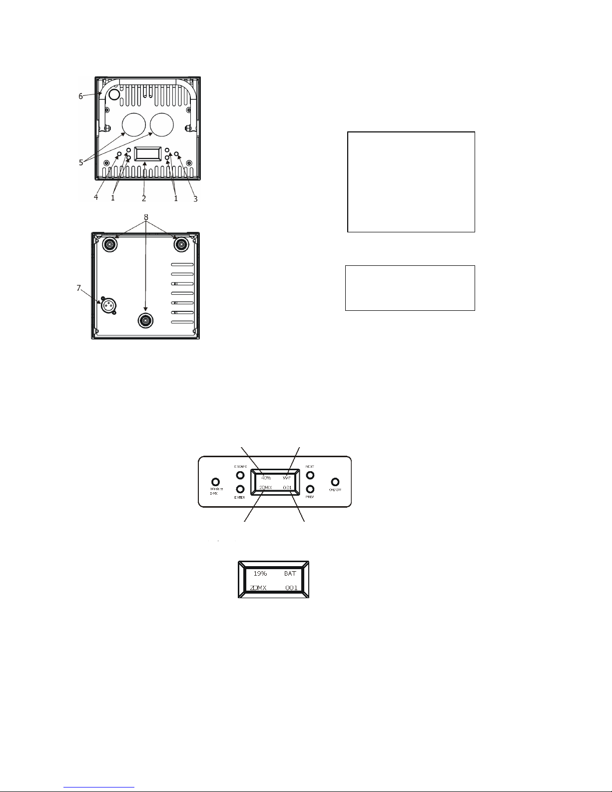
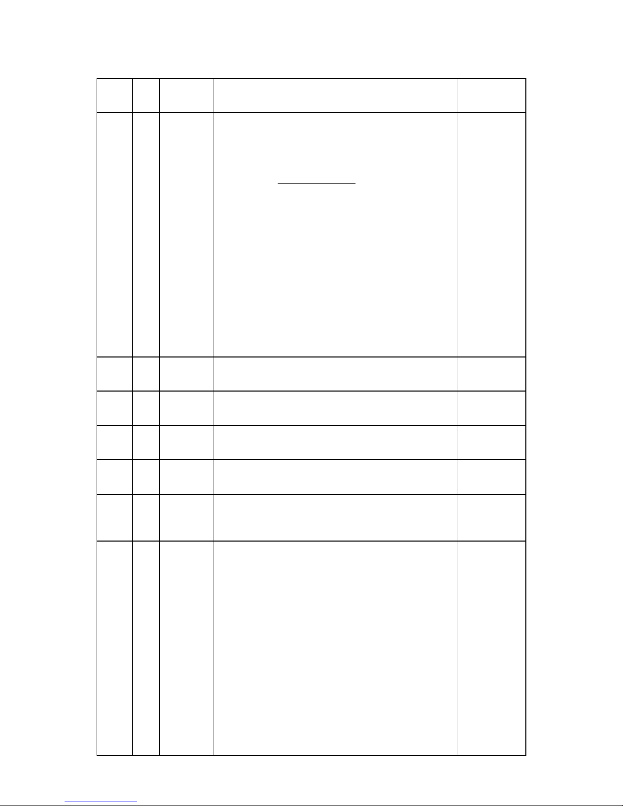
P EV and - NEXT buttons - move between menu items on the same level, sets values.
Use the PREV/NEXT buttons to scroll throu h the various menu items. To select desired item, press the ENTER.
ON/OFF button – switches on and off the LiteWare. Press and hold the button for 3 seconds.
Wireless DMX button – unlinks the device from a wireless DMX transmitter.
3.2 Low battery
When the battery volta e becomes too low (10.8V and below), the battery base unit oes to sleep and li ht output
is closed.
You must rechar e the battery base unit before you can use it a ain.
3.3 Flight case charger system
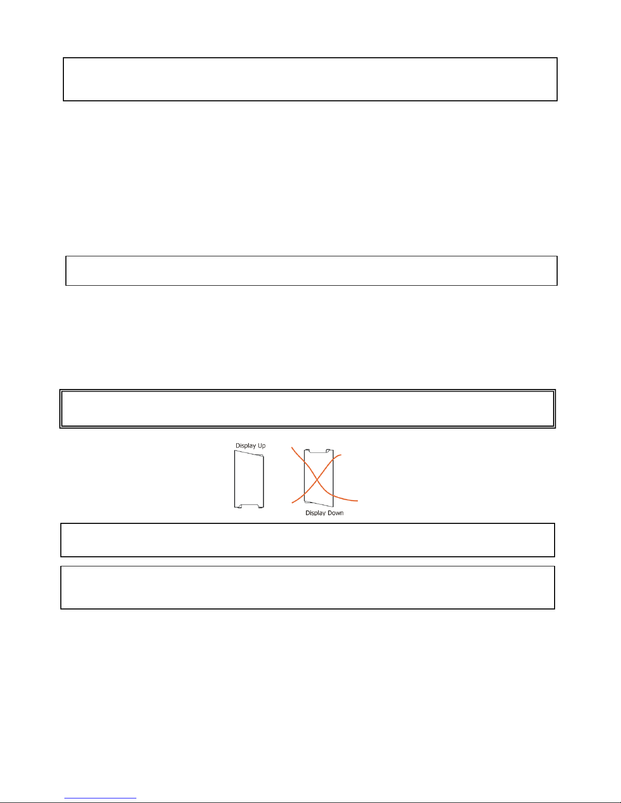
Warning!
D n t lay the flight case during charging the LiteWare units.
The flight case has t be pen during charging the LiteWare units as warm is generated.
1. Ensure that the fli ht case is plu ed into a mains supply with the supplied mains lead.
2. Place the LiteWare HO2 into the fli ht case. Do not cover the fli ht case.
Durin battery char in , the display on the battery base shows level of battery char in . By pressin the
PREV or NEXT button you can see the battery volta e, char in current and another data. When the battery
is fully char ed, the messa e “CHARGED“ will appear.
3.4 Battery care
The LiteWare HO2 contains a sealed (GEL) lead-acid battery. The battery should not be left in a
dischar ed state for lon periods because this will reduce its capacity. We recommend leavin the LiteWare HO2
on char e permanently when not in use.
The followin points should help maintain the lon life of your LiteWare battery:
• When in use, the LiteWare HO2 automatically switches off when the battery volta e reaches a set lower
limit. This is to avoid any deep dischar e dama e of the battery. It is not recommended that LiteWare batteries be
left for any prolon ed period in this state. Dischar in the battery under 70% accelerates its a in process.
• The LiteWare HO2 should always be fully re-char ed as soon as possible. Once fully char ed LiteWare HO2 can be
stored.
• If the LiteWare HO2 is to be unused for lon periods, we recommend the LiteWare HO2 is char ed every two
months to keep the batteries topped up.
• From market data, the estimated number of uses in a normal environment is around 200 cycles.
This may be hi her if the LiteWare HO2 is not run to ‘turnin off automatically’ every time. We recommend
replacin LiteWare battery every two years.
• Do not disconnect the LiteWare unit from the char in case before reachin 90% of the battery capacity.

LiteWare HO2
7
3.5 Wireless DMX operation
All fixture channels are controlled by the wireless DMX controller that you use with the the LiteWare HO2.
The fixture allows to set 2 DMX modes:
Mode 1: 9 control channels
Mode 2: 4 control channels
To link the fixture with DMX transmitter.
The fixture can be only linked with the transmitter by runnin the link procedure at DMX transmitter .
After linkin , the level of DMX si nal ( 0-100 %) is displayed in the menu item “Si nal“ (Special -->Vireless --
>Si nal).
To unlink the fixture from DMX transmitter.
The fixture can be unlinked from transmitter by means of the Wireless DMX button or usin menu item “Unlink”
(Special -->Vireless -->Unlink or DMX --> Vireless -->Unlink ).

LiteWare HO2
8
4. LiteWare H 2 - DMX protocol (
ver. 1.1
)
Mode 1 Mode 2
DMX
Value
Function
Type of
control
1 -
0-29
30-39
40-49
50-59
60-69
70-79
80-89
90-99
100-109
110-114
115-119
120-129
130-139
140-255
Special functions
Reserved
To activate following functions, stop in DMX value for at least 3 sec.
and shutter must be closed at least 3 sec. (Shutter channel 8 must
be at range of -31 DMX). Corresponding menu items are temporily
overrided except Acoustic alarm On/Off function.
RGBW colour mixin mode
CMY colour mixin mode
Acoustic alarm On
Acoustic alarm Off
Display permanent lits
Display permanent turned off
Dimmer curve: linear
Dimmer curve: square law
Colour calibration mode On
Colour calibration mode Off
Load: Eco
Load: Full
Reserved
step
step
step
step
step
step
step
step
step
step
step
step
step
2 1
0-255
ed
(Cyan)
Red LEDs saturation control (0-100%)
proportional
3 2
0-255
Green
(Magenta)
Green LEDs saturation control (0-100%)
proportional
4 3
0-255
Blue
(Yellow)
Blue LEDs saturation control (0-100%)
proportional
5 4
0-255
White
( GBW mode only)
White LEDs saturation control (0-100%)
proportional
6 -
0
1-255
CT0
No function
Colour temperature correction
step
proportional
7 -
0
1-2
3
4-5
6
7-9
10-12
13-15
16
17-55
56
57 - 95
96
97 – 134
135
Virtual colour wheel
No function
White 2700 K
White 2700 K (tun sten emulation)*
White 3200 K
White 3200 K (tun sten emulation)*
White 4200 K
White 5600 K
White 8000 K
Blue (Blue=full, Red+Green+White=0)
Red=0, Greenup,Blue =full, White=0
Light Blue
(Red=0, Green=full, Blue =full, white=0)
Red=0, Green=full, Bluedown, White=0
Green (Red=0, Green=full, Blue =0, White=0)
Redup, Green=full, Blue=0, White=0
Yellow
(Red=full, Green=full, Blue=0,White=0)
step
step
step
step
step
step
step
step
step
proportional
step
proportional
step
proportional
step

LiteWare HO2
9
136
-
174
175
176 -214
215
216-246
247
248
249
250-255
Red=full, Green
down, Blue=0, White=0
ed(Red=full, Green=0, Blue=0, White=0)
Red=full, Green=0, Blueup, White=0
Magenta
(
Red=full, Green=0,Blue=full,White=0)
Reddown, Green=0, Blue=full, White=0
Blue (Red=0, Green=0, Blue=full, White=0)
Rainbow effect( with fade time)
Rainbow effect(without fade time)
Reserved
proportional
step
proportional
step
proportional
step
step
step
8 -
0-31
32-63
64-95
96-127
128-143
144-159
160-191
192-223
224-255
Shutter/ Strobe
Shutter closed
Shutter open
Strobe-effect from slow to fast
Shutter open
Openin pulses in sequences slow--> fast
Closin pulses in sequences fast --> slow
Shutter open
Random strobe-effects from slow to fast
Shutter open
step
step
proportional
step
proportional
proportional
step
proportional
step
9 -
0 - 255
Dimmer
Dimmer intensity from 0% to 100%
proportional
*Halo en lamp effect durin dimmin

LiteWare HO2
10
5. Control menu map
Default settings=Bold print
Menu Level 1
Menu Level 2
Menu Level 3
Menu Level 4
Menu Level 5
Menu Level 6
DMX
Set DMX
001
-
512
DMX
Pres.
Mode 1, Mode 2
Wireless
Si nal
Unlink
InFo
P
On
.
Time
Total
Reset
DM.In.
Spec.
0
-
255
:
Dimmer
0
-
255
Temp.
Current
Led
Board
Board 2
Hi hest
Led
Board
Board 2
Hi h Res
Led
Board
Board 2
Battery
Capacity (%)
Volta e (V)
Current (mA)
Temp (°C)
Tot. Cap. (Ah)
Case Ver
Spec. F. State
Sw Ver.
IC1
IC2

LiteWare HO2
11
Menu Level 1
Menu Level 2
Menu Level 3
Menu Level 4
Menu Level 5
Menu Level 6
PErS
DMX
Pres.
Mode 1
Mode 2
Alarm
Settin
ENT. PASW.
1
-
255
Alarm On/Off
On,
Off
Sensitivity
0…
13
…15
M
.
F
.
Time
0..
0.
8
…
25.5
Dimmer
Square Law
Linear
Display
On/Off T
On
,
Off
Contrast
0
-
100
%
Bckli ht
0
-
100
%
Load
full
eco
Col.
c
al. mod.
On
, Off
Col.
mix
. mod.
GBW
, CMY
Temp. Uni.
°C
, °F
Aut. Off
Off
0.1h
-
25.5h
I
. EF. Pos.
Spec.
0
-
255
:
Dimmer
0
-
255
Stor
e
Defaults
M
anual
Spec.
:
Dimmer
Test Pr
St
a. Alone
Auto
Run
Off

LiteWare HO2
12
Menu Level 1
Menu Level 2
Menu Level 3
Menu Level 4
Menu Level 5
Menu Level 6
Test
Pro 1
:
Pro 3
Pr.
P
lay
Test Pr
Pro 3
Pr.
Edit
P
ro
1
St
ep
.01
Pr . En.
1
-
40
:
:
Spec.
0
-
255
Pr
o
.3
St
ep
.
40
:
:
S.
T
im.
0
-
25.5
s
F. Tim
0
-
25.5
s
Co
py
S
pecial
rdM Low
rdM
H
i h
Wireless
Si nal
Unlink
Hold DMX
On
, Off
Bat
t
ery init
Start
No
Yes
Chan e password
OLD PASSW
1
-
255
NEW PASSW
1
-
255
CON. PASSW
1
-
255
Adjust
DMX Val.
Spec.
0
-
255
:
Dimmer
0
-
255
Cal. Col.
.
Ready C.
Red C.
0
-
255
Grn C.
0
-
255
Blu C.
0
-
255
Whi C.
0
-
255
Store

LiteWare HO2
13
Menu Level 1
Menu Level 2
Menu Level 3
Menu Level 4
Menu
Level 5
Menu Level 6
Cal.temp
C. 2700K
Red
:
Green
C. 8000K
Blue
White
Cal. Def.
No
Yes
Case SW Upd
6. Fixture menu
6.1 Fixture Address
Use this menu to set the DMX address and DMX mode of the fixture.
Set DMX --- Set DMX address. Select this submenu to set a DMX start address.
To set a DMX address.
1. Use the PREV/NEXT buttons to find “Set DMX“.
2. Press the ENTER button.
3. Use the PREV/NEXT buttons to select desired start address.
4. Press the ENTER button to confirm the choice.
DMX Pres --- DMX preset. Select this menu item to set a desired DMX mode. Please refer to the chapter "DMX
protocol" for detail description of each DMX mode.
Note: After switchin on, the LiteWare HO2 will automatically detect whether DMX 512 data is received or not.
If there is no data received at the DMX input, the display will start to flash with actually set address.
Wireless --- Signal –
The item serves for readin of the level of DMX si nal.
Unlink -
The item serves for unlinkin the fixture from the transmitter.
6.2 Fixture information
Use this menu to read useful information about the fixture status.
To display desired information.
1. Use the PREV/NEXT buttons to find the “ InFo“ menu.
2. Press the ENTER button.
3. Use the PREV/NEXT buttons to select the required menu item.
4. Press the ENTER button to confirm the choice.
Pon Time ---Power On Time. Use the menu item to read the number of operation hours of the fixture.

LiteWare HO2
14
Total - the function shows the total number of the operation hours since the LiteWare HO2 has
been fabricated.
eset - the function shows the number of the operation hours that the LiteWare HO2 has been
powered on since the counter was last reset.
In order to reset this counter to 0 you have to press the ENTER button, then by means of the PREV
and NEXT buttons select “Yes”and press the ENTER button a ain.
DM In ---DMX values. Select this function to read DMX values of each channel received by the fixture.
Temp ---Fixture Temperatures. Select this menu to read the temperature of the fixture:
Current - the current temperature of the fixture inside.
Highest - the menu item shows the max. temperatures of the fixture inside since
the LiteWare HO2 has been fabricated.
High es. - the menu item shows the maximum temperatures of the fixture inside since
the counter was last reset. In order to reset this counter, you have to press the ENTER button,
then by means of the PREV and NEXT buttons select “Yes”and press the ENTER button a ain.
Measurin points: Led - temperature on the PCB with LEDs.
Board – first temperature on the PCB of the control electronic.
Board 2- second temperature on the PCB of the control electronic.
The temperatures can be displayed in either °C or °F units - see option “Temp. Uni.“ in the menu “Pers“.
Spec. F. State ---Special function stare. The menu item shows current state of switchin functions on DMX channel
1.
Battery ---Battery information. Select this menu to read the battery state.
Capacity - capacity of the battery in %. Fully char ed battery shows 100%.
Note: in the Full mode, the LiteWare unit can be switched off automatically when capacity has
fallen under 13%.
Voltage – volta e of the battery in V.
Current – current of the battery in mA. Symbol “–“ means dischar in , “+” means char in .
Temp – temperature of the electronic controllin the battery.
Tot. Cap. – Total capacity of the battery in Ah.
Case Ver. – Software version of the char in case.
Sw Ver ---Software Version. Select this function to read the software version of the LiteWare unit.
6.3 Personality
Use this menu to modify the LiteWare HO2 operatin behaviour.
DMX Pres --- DMX preset. Select this menu item to set a desired DMX mode. Please refer to the chapter "DMX
protocol" for detail description of each DMX mode.
Alarm Setting --- Acoustic alarm . If this alarm is on, the sensor si nalizes unwanted relocation of the LiteWare
unit.
After final placin , switch the acoustic alarm on (you can also use DMX command – see DMX chart, channel
“Special function”. Do not for et to switch the sensor off prior to manipulate with the LiteWare units!
To switch the acoustic alarm on:
1. Enter the “Alarm” menu.
2. Enter the password (default password is “001”) usin the PREV/NEXT buttons and confirm with the ENTER
button .

LiteWare HO2
15
3. Use the PREV/NEXT buttons to select menu item “ Alarm On/Off”, press the ENTER button and select
option “On” ( if you want to deactivate the acoustic alarm, select option “Off”) and confirm with the
ENTER button.
The menu item “Sensitiv” allows to set desired sensitivity (0-min. sensitivity, 15 max. sensitivity) of the acoustic
alarm sensor. This sensitivity can be affected by material on which the LiteWare unit stands.
Note: the acoustic alarm is automatically set off if:
- the LiteWare unit is inserted into char in case, which is conected to mains.
- the LiteWare unit is 25.5 hours in a sleep mode (without action) out of the char in case or in the
char in case which is not connected to mains.
M. F. Time --- Max. fade time. Select this menu item to set a desired max. fade time (0-25.5 sec.). This adjusted
fade time influences fade of R,G,B,W and dimmer durin DMX operation:
If time between two receivin DMX values is > than the fade time set in the item “M Ftime“, the entire adjusted
fade time will be used.
If time between two receivin DMX values is < than the fade time set in the item“M Ftime“, the adjusted fade time
will be reduced to fill entire time between the two receivin DMX values.
e. “M Ftime“=2sec. and fixture has received Red=0 DMX, after 5 seconds will receive Red=255 DMX. It means, that
red will o to full intensity durin 2 seconds.
“M Ftime“=8 sec. and fixture has received Red=0 DMX, after 5 seconds will receive Red=255 DMX. It means, that
red will o to full intensity durin 5 seconds (max. fade time is reduced from 8 sec. to 5 sec.).
Dimmer --- Dimmer curve. The menu item allows to select dimmer curve: Linear or Square Law.
Display. --- Display adjusting. This function allows you to chan e the display settin s.
On/Off T -
This function allows you to keep the display permanent on or turn it off two seconds
after last pressin any button on the control panel.The function is also available on the channel 1
(DMX ran e of 70-89).
Contrast -
Use this function to adjust contrast of the display (0-100%).
Bcklight -
Use this function to adjust backli ht of the display (0-100%).
Load --- LEDs power. The menu allows to set two modes of LEDs power.
full –
max. power of LEDs (500mA LED current), max li ht output
.
eco –
economic mode (350mA LED current), lon er operation time of the LiteWare unit.
Col. cal. Mod. - Colour calibration mode. If the functin is on, the white output (2700K-8000K) from the fixture (and
also mixed colours) is more uniform,. Each colour is dynamically corrected accordin to the value set in the menu
"Cal Col." and “Cal Temp”. (Special-> Adjust-> Cal. Col.).
Note: If colour calibration mode is on, the colour temperature of full RGBW (R+G+B+W=255DMX) is 8000K.
Col. mix. Mod. - Colour mixing mode. This item allows switchin into RGBW or CMY mode. In the CMY mode, the
white channel is not active.
Temp. Uni. --- Temperature Unit. Use this menu in order to display the fixture temperatures in desired units: °C or
°F.
Aut Off. – Automatic switching off. The function allows to switch the LiteWare unit off automatically if DMX si nal
is missin . The time period after that the unit will be switched off can be set from 0.1hour to 25.5 hours.
I. Ef. Pos --- Init effect positions. Use this function to set all effects to the desired positions to which they will move
after switchin the fixture on (if DMX is not bein received).
Defaults --- Default Settings.The menu item sets fixture parameters to the default (factory) values except menu
items “Alarm Settin ” and “Chan e Password” (from menu Special).

LiteWare HO2
16
6.4 Manual mode
Use this menu for control the fixture without connected DMX console.
To control fixture channels.
4. Use the PREV/NEXT buttons to find “ Manual“ menu.
5. Press the ENTER button.
6. Use the PREV/NEXT buttons to select desired effect (channel).
List of control channels:
“Spec.” – special functions
“Red” - red LEDs saturations
“Green“ - reen LEDs saturations
“Blue“ - blue LEDs saturations
“White“ - white LEDs saturations
“C TC“ - a colour temperature correction
“C Wheel“ - a virtual colour wheel
“Strobe“- a strobe, shutter
“Dimmer“- a dimmer
7. Press the ENTER button and use the PREV/NEXT buttons to set value , press the ENTER button to confirm it.
Note: the switchin functions as a colour mixin mode, acoustic allarm and colour calibration mode cannot be
controlled from this menu, use the menu “Personality” for chan in their settin s.
6.5 Test program
Use this menu to run demo-test sequences without an external controller, which will show you some possibilities
of usin the LiteWare HO2.
6.6 Stand-alone setting
The fixtures on a data link are not connected to the controller but can execute pre-set pro rams which can be
different for every fixture.
Auto un --- Automatic playback. This function allows you to select the pro ram which will be played after
switchin the fixture on. Selected pro ram will be played continuously in a loop.
1. Use the PREV/NEXT buttons to find “ Sta Alone“ menu.
2. Press the ENTER button.
3. Use the PREV/NEXT buttons to select “ Auto un“ item.
4. Press the ENTER button.
5. Use the PREV/NEXT buttons to select desired pro ram.
6. Press the ENTER button to confirm the choice.
Pr. Play --- Playing program. By enter to this menu a complete overview of all pro rams is offered, from which the
pro ram to be run can be selected.
1. Use the PREV/NEXT buttons to find “Pr. Play“ menu.
2. Press the ENTER button.
3. Use the PREV/NEXT buttons to select desired pro ram.
4. Press the ENTER button. The selected pro ram runs in a loop.
Pr. Edit --- Editing a program. The fixture offers 3 freely editable pro rams (Pro .1-Pro .3) each up to 40 steps.
Every pro ram step includes a fade time-the time taken by the step´s channel status to reach the desired level and
a step time-the total time occupied by the step in the pro ram.

LiteWare HO2
17
E. . If “F.tim.“=5 second and “S.tim.“=20 second, effects will o to the desired position durin 5 seconds and after
that they will stay in this position for 15 seconds before oin to the next pro . step
1. 1. Use the PREV/NEXT buttons to find “ Sta Alone“ menu and press the ENTER button.
2. Use the PREV/NEXT buttons to select “Pr. Edit“ menu and press the ENTER button.
3. Use the PREV/NEXT buttons to select a pro ram you want to edit (Pro .1-Pro .3) and press ENTER button.
4. Use the PREV/NEXT buttons to select a desired pro ram step ("Step 01" - "Step 40") and press ENTER
button.
5. Use the PREV/NEXT buttons to select a channel you want to edit and press the ENTER button.
List of editable items:
“Pr .En” - a number of last pro ram step (value 1-40). This value should be set before start
pro rammin (e. . if you want to create pro ram with 10 steps, set Pr .En=10).
“Spec.” – special functions
“Red” - red LEDs saturations
“Green“ - reen LEDs saturations
“Blue“ - blue LEDs saturations
“White“ - white LEDs saturations
“C TC“ - a colour temperature correction
“C Wheel“ - a virtual colour wheel
“Strobe“- a strobe, shutter
“Dimmer“- a dimmer
“F.tim.“- a fade time, (0-25.5) seconds
“S.tim.“ - step time, value (0-25.5) seconds
“COPY“. – this item duplicates the current pro . step to the next pro . step. The item “Pr En” is increased
automatically.
6. Use the PREV/NEXT buttons to set a DMX value of the channel and then press the ENTER button.
7. Use the PREV/NEXT buttons to select next channel and press the ENTER button.
8. After havin set all channels in the current pro ram step, press the MODE button to o by one menu level
back and select another pro ram step.
6.7 Special functions
rdM Low --- DM Code.This menu item shows the first part of the RDM identification code.
rdM High --- DM Code. This menu item shows the second part of the RDM identification code.
Wireless --- Signal –
The item serves for readin of the level of DMX si nal.
Unlink -
The item serves for unlinkin the fixture from the transmitter.
HoLd DMX --- If the function is on, the last received DMX values are held in case, that DMX data receivin was
interrupted (e. . disconnected DMX controller).
Change password --- Use the munu to chan e your password. The password is required if you need to enter the
menu “Alarm”. Factory default password is “001”.
To chan e password.
1. Enter the “Chan e password” menu.
2. Enter the old password usin the PREV/NEXT buttons and confirm with the ENTER button .
3. Set the new password usin the PREV/NEXT buttons and confirm with the ENTER button. As password you
have to select one number from ran e 1-255.
4. Repeat the new password.

LiteWare HO2
18
Note: when you enter old password menu, the si n “000” is displayed althou h some number was set.
Battery init ---Battery initialization. Use this function in a special case, e. . after chan in the battery.
The battery initialization runs in two steps (char in and dischar in ). When you select “Yes”, and o to the first
screen of the display, the si n “ Battery Init St1” appears on a rota basic with the first screen. Place the LiteWare
unit into char in case (connected to mains) until the battery is fully char ed (messa e “CHARGED“ is displayed).
Place the LiteWare unit outside the case and switch the display on. The display shows “ Battery Init St2” on a rota
basic with the first screen and the unit li hts. Let the battery dischar e until li ht output is closed. Do not interrupt
this action. Durin this step, DMX control and char in of the unit is disabled.
When the battery is dischar ed, the battery initialization is completed.
After char in the battery, the LiteWare unit is prepared for operation.
Note: durin the battery initialization process, the LiteWare unit has to be switched into eco mode.
Adjust - Adjustment. The menu allows the fine adjustment of colours.
DMX Val- DMX values. Use the menu to set DMX values of fixture´s channels.
Cal Col - A calibration o red, reen, blue and white colours by means of an automatic calibration
with a factory equipment.
eady C. – when this item is displayed, the LiteWare unit stops receivin wireless DMX
si nal and starts receivin wired DMX via 3-pin XLR (char in connector).
ed C – red LEDs saturation (0-255)
Grn C – reen LEDs saturation (0-255)
Blu C – blue LEDs saturation (0-255)
Whi C – white LEDs saturation (0-255)
Store – saves adjusted values
Cal Temp – Selection of colour temperature for manual calibration: 2700K, 3200K, 4200K, 5600K,
8000K.
Manual colour calibration:
1. Switch the fixture on, set full mode (menu “Personality”), o to the menu “Manual” and set the
shutter,dimmer, red, reen, blue and white channel at 255DMX, aim the beam at wall in distance cca 5m
and let the fixture heat up.
2. Go to the “Manual” menu and set the C Wheel at 1 DMX (2700K)
3. Go to the “Cal temp” menu, select “2700K” item and by means of the Red , Green, Blue and White items
adjust the 2700K colour temperature as exactly as possible (∆u´v´= 0).
After calibration, press the “Store“ item to save adjusted values.
4. Go to the “Manual” menu and set the C Wheel at 4 DMX (3200K).
5. Go to the “Cal Temp” menu, select “3200K” item and by means of the Red , Green , Blue and White items
adjust the 3200K colour temperature as exactly as possible (∆u´v´= 0).
After calibration, press the “Store“ item to save adjusted values.
6. Repeat this procedure for rest of colour temperatures (4200K, 5600K, 8000K).
7. Software update
The followin are required in order to update software in the LiteWare unit or char in case:
- PC runnin Windows XP/Vista/7/8 /Linux/OSX with connection to the Internet
- ROBE RDM Uploader
- Robe Universal Interface WTX (RUNIT WTX)
Note: Both software update and case software update should execute a qualified person. If you lack qualification,
do not attempt the update yourself and ask for help your ROBE distributor.
Before startin both updates, the LiteWare unit has to be char ed!
Note: pro rams 1-3 and all items in the menu "PErS" and “Special” will be set to their default values (except menu
“Alarm Settin ”) after software update.

LiteWare HO2
19
To update software in the LiteWare unit
NOTE: The Liteware unit must not be in char in case durin software update.
I. Installation of the ROBE RDM Uploader.
1. ROBE RDM Uploader is available from the ROBE web site at WWW.robe.cz.
2. Make a new directory ( e. . Robe_Uploader) on your hard disk and download the software into it.
3. Install the software on your computer.
II.Fixture software updatin .
1. Connect your PC with the USB input of the RUNIT WTX.
Turn both the computer and the LiteWare unit on (shutter should be closed).
We recommend to cancel all runnin pro rams before startin the ROBE RDM Uploader.
2. Run the ROBE RDM Uploader and perform software update of the LiteWare unit.
Avoid interruptin the update process.
To update software in the charging case
Install the RUNIT WTX and the ROBE RDM Uploader software as described above.
Note: The char in case has to be empty before case software update.
1Take one char ed LiteWare unit outside the case and switch it on (shutter has to be closed).
2Use the PREV/NEXT buttons to find “Special“ menu.
3Press the ENTER button.
4Use the PREV/NEXT buttons to find “ Case SW Upd“ item. Press the ENTER button.
5The notice “ In case? no“ will appear.
6Insert the LiteWare unit into case.
7Use the PREV/NEXT buttons to select “yes” item, confirm by pressin the ENTER button.
8The si n “ wait“ will appear.
9Run the ROBE RDM Uploader and perform software update of the char in case.
It may last several minutes to perform software update.
8. RDM
This fixture is ready for RDM operation.RDM (Remote Device Mana ement) is a bi-directional communications
protocol for use in DMX512 control systems, it is the new open standard for DMX512 device confi uration and
status monitorin .
The RDM protocol allows data packets to be inserted into a DMX512 data stream without adversely affectin
existin non-RDM equipment. By usin a special „Start Code,“ and by complyin with the timin specifications for
DMX512, the RDM protocol allows a console or dedicated RDM controller to send commands to and receive
messa es from specific movin li hts.
RDM allows explicit commands to be sent to a device and responses to be received from it.
The list of commands for LiteWare HO2 is the followin .

LiteWare HO2
20
Parameter ID Discovery command SET command GET command
DISC_UNIQUE_BRANCH *
DISC_MUTE *
DISC_UN_MUTE *
DEVICE_INFO
*
SUPPORTED_PARAMETERS
*
SOFTWARE_VERSION_LABEL
*
DMX_START_ADDRESS
* *
IDENTIFY_DEVICE
* *
DEVICE_MODEL_DESCRIPTION
*
MANUFACTURER_LABEL
*
DEVICE_LABEL
*
*
SENSOR_DEFINITION
*
SENSOR_VALUE
*
DISPLAY_LEVEL
*
*
DEVICE_RESET
*
DMX_PERSONALITY
*
*
DMX_PERSONALITY_DESCRIPTION
*
STATUS_MESSAGES
*
STATUS_ID_DESCRIPTION
*
DEVICE_HOURS
*
9. Information and error messages
CHARGED – the LiteWare is fully char ed and ready for operation.
CHARGE NOW – the battery of the LiteWare is dischar ed and has to be placed to the fli ht case in order
to char e it.
CHECK BATTERY – run the “Battery init“ procedure from the menu Special.
Table of contents
Other Robe Home Lighting manuals
Popular Home Lighting manuals by other brands

Safavieh
Safavieh LIT4159 quick start guide

Endon
Endon 107527 Installation and safety instructions

RH
RH HEXAGONAL CRYSTAL COLUMN FLOOR LAMP quick start guide

TI
TI 31918 Assembly and mounting instructions

Safavieh Lighting
Safavieh Lighting NAVO TBL4234A manual

Briloner
Briloner MAL 2083 Mounting instructions