ROBEL 13.80 User manual

Version 2a, Status 24.05.2013 1380-BA-V2a-EN.doc
Original Operating Instructions
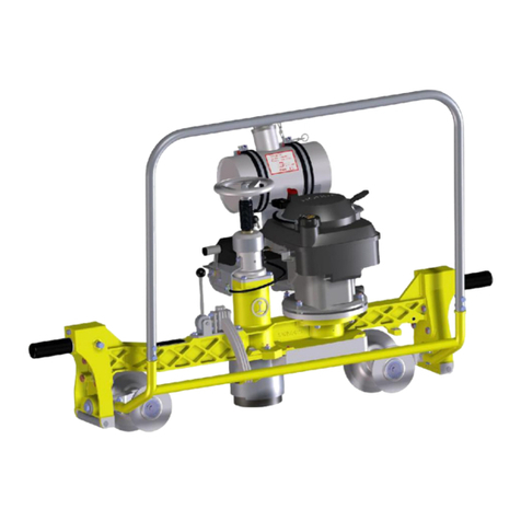
Rail Cutter
Type 13.80
(With three-phase motor, symbol image)
Robel Bahnbaumaschinen GmbH
Industriestraße 31,
83395 Freilassing
e-mail:
Internet:
info@robel.com
www.robel.com
Telefon/Phone/Téléfone
Telefax/Fax
(08654) 609-0
(08654) 609-445
These operating instructions were produced in accordance with the
current state of technology at the time of printing.
The right to change on the basis of further developments is reserved.
Dimensions and weights are approximated.
Photographs show special layouts in some cases.


13.80
RAIL CUTTER
INDEX
1TECHNICAL DATA ............................................................. 1
1.1 Drive motor.........................................................................................1
1.2 Cutting disk (300 Ø) ...........................................................................1
1.3 Cutting disk (350 Ø) ...........................................................................1
1.4 Dimensions ........................................................................................1
1.5 Weights ..............................................................................................2
1.6 Safety blocking wedge device (if ordered) ........................................2
2SAFETY .............................................................................. 3
2.1 General dangers.................................................................................3
2.2 Information about dangers ................................................................3
2.3 First aid ..............................................................................................3
2.4 Abrasive cutter...................................................................................4
2.5 Personal protective equipment..........................................................4
3MACHINE DESCRIPTION................................................... 5
3.1 Designated use ..................................................................................5
3.2 Foreseeable misuse ...........................................................................5
3.3 Components.......................................................................................5
3.4 Front view...........................................................................................6
3.5 Abrasive cutter...................................................................................7
3.6 Engine –Automatic Cut-Out (optional)..............................................9
3.7 Safety blocking wedge device (13.81)..............................................10
3.8 Wheel protection for the cutting disk ..............................................11
4OPERATING CONDITIONS .............................................. 13
4.1 Storage.............................................................................................13
4.2 Transport..........................................................................................14
5START-UP ........................................................................ 15
5.1 Personal protective equipment........................................................15
5.2 Checks..............................................................................................15
5.3 Positioning the guiding frame..........................................................16
5.4 Fastening the abrasive cutter with the spindle................................17

13.80
RAIL CUTTER
5.5 Starting the engine...........................................................................18
5.6 Test run ............................................................................................20
5.7 Abrasive cutting...............................................................................21
6MAINTENANCE.................................................................25
6.1 Changing the abrasive .....................................................................26
6.2 Readjusting the belt tension/Changing the belt ..............................27
6.3 Adjusting the cutting line.................................................................28
6.4 Maintenance schedule .....................................................................29
7APPENDIX A .....................................................................31
7.1 Safety Standards for electric drives.................................................31
8APPENDIX B .....................................................................33
8.1Area of application...........................................................................33
8.2 Liability exclusions ..........................................................................33
8.3 Copyrights........................................................................................33
8.4 General regulations..........................................................................34
8.5 Acceptance, equipment and operating licence ...............................34
8.6 Safety regulations ............................................................................35
8.7 Protection and use of the machine ..................................................35
8.8 Intended audience for the operating instructions ...........................36
8.9 Accident prevention.........................................................................36
8.10 Safety principles ..............................................................................37
8.11 Special types of danger ...................................................................37
8.12 Dangers due to electrical energy .....................................................38
8.13 Dangers due to heat .........................................................................38
8.14 Other dangers –safety devices .......................................................38
8.15 Fire risk ............................................................................................39
8.16 Fire protection..................................................................................39
APPENDIX: EC-DECLARATION OF CONFORMITY

Page 1
13.80
RAIL CUTTER
1 TECHNICAL DATA
1.1 Drive motor
Three-phase motor, 400 V, 50 Hz
Power at 2850 1/min
2,7 kW
1.2 Cutting disk (300 Ø)
Diameter, outside / borehole x width
300/22.2x3 mm
Speed of the grinding wheel, max. permitted
5090 revs/min
Circumferential speed, max. permitted
80 m/s
Weight
0.5 kg
1.3 Cutting disk (350 Ø)
Diameter, outside / borehole x width
350/22.2x3 mm
Speed of the grinding wheel, max. permitted
5090 revs/min
Circumferential speed, max. permitted
100 m/s
Weight
0.8 kg
1.4 Dimensions
Rail abrasive cutting machine (without cutting disk)
Length
675 mm
Depth
360 mm
Height
380 mm
Guiding frame
Length
550 mm
Depth
350 mm
Height
310 mm

Page 2
13.80
RAIL CUTTER
1.5 Weights
Rail abrasive cutting machine (without cutting disk)
29.5 kg
Guiding frame
12 kg
1.6 Safety blocking wedge device (if ordered)
Length
180 mm
Depth
200 mm
Height
40 mm
Weight
1.5 kg

Page 3
13.80
RAIL CUTTER
2 SAFETY
2.1 General dangers
The machine has been constructed and built to cut rails at an exact right angle,
without using coolants, and may only be used for this purpose. The protective
devices on the machine meet current safety regulations; they must be attached
continually during operation. Personal protective equipment must be worn
during work!!
For further information, see Appendix A.
2.2 Information about dangers
All the following information and instructions are intended to protect the
operator’s personal safety and physical well-being against dangers and the
assets of the company operating the machine from damage. The instructions on
hand consistently use certain terms to distinguish between types of danger and
the level of consequences to be expected from not complying with instructions.
These are as follows:
DANGER points out that non-compliance with instructions
may result in death or severe injury to the operator or
considerable damage to the operating company’s assets.
CAUTION points out that non-compliance with instructions
may result in injury to the operator or damage to the
operating company’s assets.
INFORMATION contains important information about the device,
its operation or about a section of the instructions on hand.
2.3 First aid
Always ensure that proper “first aid” equipment is provided.
Consult the medical service or doctor at your office regarding “first aid”
measures and appropriate equipment.

Page 4
13.80
RAIL CUTTER
2.4 Abrasive cutter
Use of products which cut, grind, drill, sand or shape
material can generate dust and vapors which may contain
harmful chemicals. Know the nature of the material being
worked on and wear appropriate dust mask or respirator
protection.
•Before starting the machine, always check whether the wheel protection is
mounted correctly.
•Make sure that no clothing or body parts can come in contact with the
cutting blade.
•Do not start the power cutter without the cutting arm or cutting head fitted.
Otherwise the clutch can come loose and cause personal injury.
•Ensure that you and the machine stand firmly and that the cutting blade
rotates freely.
•Make sure no unauthorised persons are within the working area.
Free-hand use and hand guided use
are strictly prohibited.
•The rail cutter 13.80 must only be used together with the
guiding frame.
2.5 Personal protective equipment
•Basic health and safety requirements must be observed.
•Wear protective helmet.
•Wear eye protection!
Ideally, a polycarbonate (safety glass), pull-down visor,
which is firmly fixed to the protective helmet; at the very
least, approved safety glasses (closed on all sides).
•Wear suitable ear protection against high frequency sound.
•Wear steel-capped working shoes.
•Wear tight fitting clothing in the lower leg and arm area!

Page 5
13.80
RAIL CUTTER
3 MACHINE DESCRIPTION
3.1 Designated use
The machine has been constructed and built to cut rails at an exact right angle,
without using coolants, and may only be used for this purpose.
Abrasive cutter and guiding frame are assigned to each other with steel
stamping letters (machine number).
3.2 Foreseeable misuse
Free-hand cuts are not permissible!
The rail cutter 13.80 may only be used in conjunction with the guiding frame.
3.3 Components
The ROBEL 13.80 rail cutter consists of an abrasive cutting machine and a
guiding frame to be fastened to the rail.
1
Motor (symbol image above)
2
Bearing arm
3
Protection
4
Guiding frame

Page 6
13.80
RAIL CUTTER
3.4 Front view
1
Adjusting screw for wheel protection
2
Wing nut for covering

Page 7
13.80
RAIL CUTTER
3.5 Abrasive cutter
The interchangeable cutting disk is driven by a three-phase motor via a fan belt.
1 Motor
7 Attachment for guiding frame
2 Safety switch
8 Tightening screw motor / separating arm
3 Plug
9 Cutting disk
4 Front handle (motor arch)
10 Wheel protection
5 Handle (right hand grip)
11 Adjusting screw for wheel protection
6 Bearing arm

Page 8
13.80
RAIL CUTTER
3.5.1 Guiding frame
1 Upper guiding arm
2 Locking spindle
(rotating)
3 Screw grip
4 Clamping foot
5 Carrying handle
6 Spring
7 Tommy screw
8 Guiding joints
9 Lower guiding arm
The guiding frame consists of the upper guiding arm and the lower guiding arm,
which is joined with a hinge by means of a ball bearing. The lower guiding arm is
in turn connected to the clamping foot by a hinge. Both the upper and the lower
guiding arm can be guided with the abrasive cutter on both sides of the rail via
both guiding joints.
The guiding frame is robustly designed and allows complete rail separation,
even if the cutting disks are worn, without the process having to be interrupted
and the device having to be dismounted.
The spring ensures the equilibration of the abrasive cutter.

Page 9
13.80
RAIL CUTTER
3.6 Engine –Automatic Cut-Out (optional)
The automatic engine cut-out shuts down the engine or prevents it from starting
up if the rail cutter is not secured to the guide frame.
An electrical contact is made once the locking spindle has been inserted and
tightened. Only then can the rail cutter be started up. The contact is broken once
the locking spindle has been removed - the rail cutter can no longer be started
up.

Page 10
13.80
RAIL CUTTER
3.7 Safety blocking wedge device (13.81)
(if ordered)
1381-002
1381-005
1 Blocking wedge 1a Locking hole in blocking wedge
2 Pulling wedge 2a Locking hole in pulling wedge
3 Pulling mechanism
4 T-handle
The safety blocking wedge device, combined with abrasive cutters, safely
prevents the cutting disk jamming due to stressed rails caused by axial thrust.
Two special wedges are inserted in the parting line of the rail foot which has
been partially cut through and are wedged there against each other with their
surfaces parallel.
After the rails have been cut, the wedges must be removed by using a light,
manageable pulling device with a screw spindle.
These special wedges also prevent deformation of the rail foot through their
large, parallel compression area.
The force of pressure can be up to 700 kN (70 t).

Page 11
13.80
RAIL CUTTER
3.8 Wheel protection for the cutting disk
Risk of injury!
•Before starting the machine, always check whether the
wheel protection is mounted correctly.
This protective device is mounted over the cutting disk and prevents fragments
being hurled at the user duringthe separation process.

Page 12
13.80
RAIL CUTTER
This page remains empty.

Page 13
13.80
RAIL CUTTER
4 OPERATING CONDITIONS
From -20°C to a maximum of +70°C (motor temperature) with minimal power
losses at an installation height of up to 100 m mean sea level.
Risk of damage!
•Excessive solar radiation may overheat the machine to way
above +70°C. Electrical safety is endangered by distortion
of the housing.
4.1 Storage
The temperature range for storing the cutter is -20°C to +70°C. The storage
area must be dry and free of dust.
•Store the abrasive cutter in a lockable room, so that it is inaccessible to
children or unauthorised persons.
•Do not store or transport the abrasive cutter with a mounted cutting disk.
Storage of abrasives and cutting-off wheels
•Store the abrasives in appropriate shelves or containers in such a way that,
on the one hand, they cannot be damaged and, on the other hand, they can
easily be unloaded without relocating.
•Older stock ought to be used first.
•Please mind the following:
−Keep the abrasives in a dry and frost-free place.
−Store cutting-off wheels on an even support without intermediate padding
and weigh them down by means of a steel-plate or a cast iron plate.
−Pile cylndrical abrasives with soft intermediate padding.
−Store tall and straight abrasives in upright position and prevent them from
rolling.
−Keep small abrasives in adequate containers.
Correctly stored, the abrasives' shelf life is 3 –5 years (see
expiry date on respective label).

Page 14
13.80
RAIL CUTTER
4.2 Transport
The temperature range for storing the cutter is -20°C to +70°C. The cutter can
be transported on all transport routes without incurring any damage if it is
properly tied down and in its original packaging.

Page 15
13.80
RAIL CUTTER
5 START-UP
5.1 Personal protective equipment
Basic health and safety requirements must be observed!
•Wear protective helmet and eye protection!
•Wear suitable hearing protection for high-frequency sound!
•Wear safety boots with steel reinforcement!
•Wear tight fitting clothing in the lower leg and arm area!
5.2 Checks
•Before using the machine, the operating resources must be checked and
supplemented, where necessary.
•Check if cables and connections are tightly connected and undamaged
(check by view).
•Checking the cutting disk to make sure it is fixed firmly (check by hand)!
Danger!
•When using cutting disks whose attachment borehole’s
diameter is in inches, the corresponding adapter ring
must be installed together with the securing ring!
•Cutting disks which are loose are HIGHLY
DANGEROUS!
•Never work with a cutting disc that has fallen onto the
ground.
•Do not use a faulty protective cover or one that is
incorrect-ly mounted
Visual checks:
▪Check the cutting disk for cracks or other damage (cavities) and sufficient
diameter.
▪Make sure safety devices are fitted properly and undamaged and that drive
belts for the cutting disk are undamaged and sufficiently tensed .
▪Under no circumstances use defective wheel protection or wheel protection
which has not been correctly mounted.
▪Make sure the joint of the guiding frame can move freely (can be easily folded
by hand and the thread runs well).
▪The tommy screw must move freely.

Page 16
13.80
RAIL CUTTER
Refer also to the maintenance section.
5.3 Positioning the guiding frame
1
Clamping foot
2
Tommy screw
3
Guiding joints
4
Lower guiding arm
5
Distance gauge
•Place the clamping foot (1) on the rail so that the distance gauge (5) comes
to rest exactly on the marked cutting spot.
•Attach the clamping foot tightly to the rails with the tommy screw (2).
Table of contents
Other ROBEL Industrial Equipment manuals
