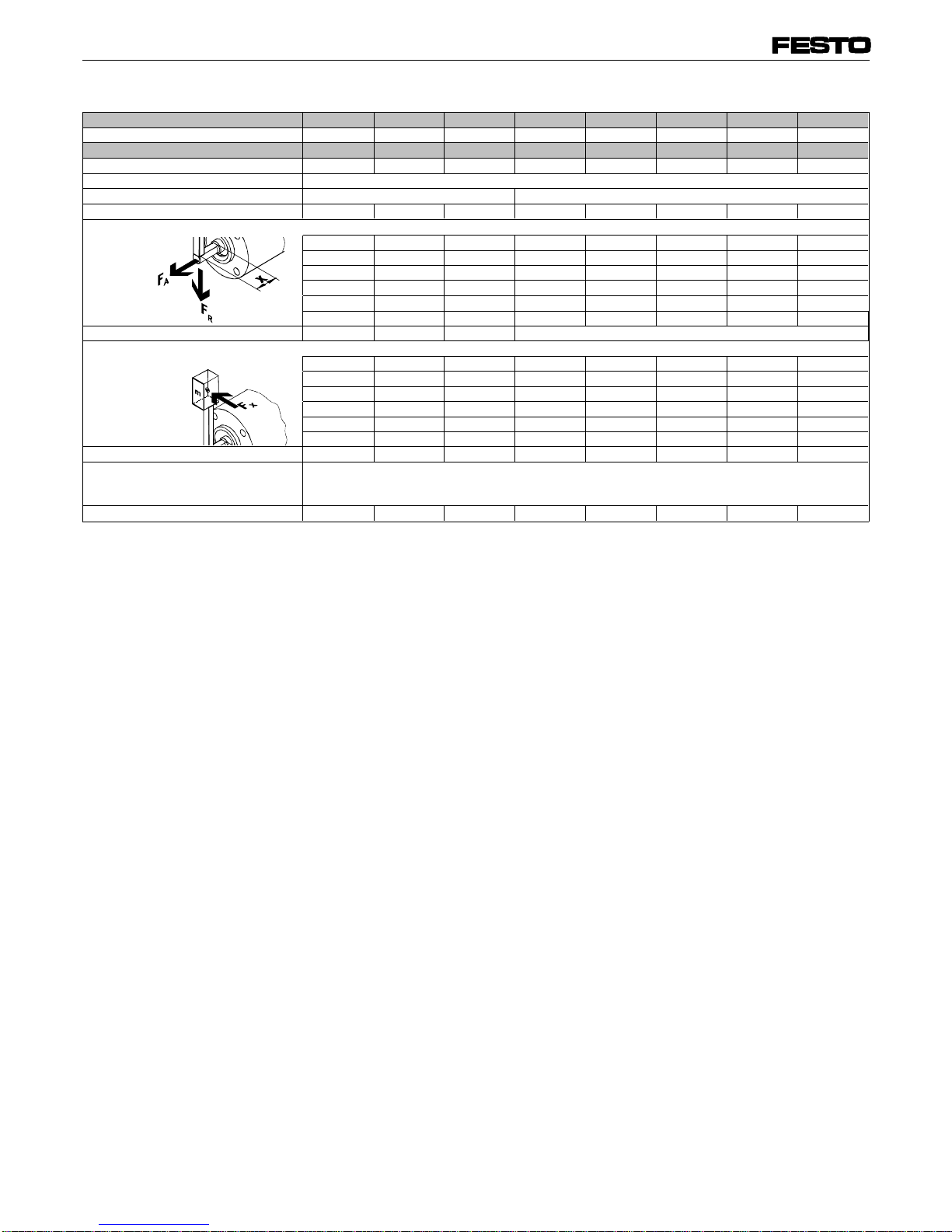
manuals.online logo
Brands
  1. Home
  2. •
  3. Brands
  4. •
  5. Festo
  6. •
  7. Industrial Equipment
  8. •
  9. Festo FLSM Series User manual

Festo FLSM Series User manual

Bedienungsanleitung
Freilauf für
Schwenkantrieb
Typ FLSM-...
Operating instructions
Freewheel unit for
swivel actuator
Type FLSM-...
Einbau und Inbetriebnahme
nur von autorisiertem Fachpersonal,
gemäß Bedienungsanleitung.
Fitting and commissioning to be
carried out by qualified personnel
only in accordance with the operating
instructions.
Es bedeuten/Symbols:
Warnung
Warning, Caution
Hinweis
Note
Recycling
Recycling
Zubehör
Accessories
397 980
0007a D/GB 1
Bedienteile und Anschlüsse Control section and
connections
1
3
1
2
4
Bild 1/Fig. 1
Anschlußgewinde für Schwenkantrieb
1
Abtriebswelle:
- bei FLSM-6/8-...: mit Abflachung
- ab FLSM-10-...: mit Paßfeder
2
Gewinde zur Befestigung der
beweglichen Masse (nur ab FLSM-10-...)
3
Gewinde zur Befestigung
4
Threaded connection for swivel actuator
1
Drive shaft
- on FLSM-6/8-...: with flat recess
- as from FLSM-10-...: with featherkey
2
Attachment thread for moving load
(only as from FLSM-10-...)
3
Mounting thread
4
2Funktion und Anwendung
Die in zwei Schwenk-Richtungen wir-
kende Bewegung des Schwenkantriebs
DSM-... wird durch den Freilaufvorsatz
nur in eine Richtung ausgeführt:
•FLSM-...-R
Rechtslauf (im Uhrzeigersinn)
•FLSM-...-L
Linkslauf (im Gegenuhrzeigersinn)
bei Blickrichtung auf Abtriebswelle.
Die andere Richtung ist gesperrt
Es resultiert eine getaktete, gleichförmi-
ge Schrittbewegung. Es lassen sich stu-
fenlos einstellbare Taktvorschübe erzie-
len.
Function and application
The bidirectional rotary movement of the
swivel actuator DSM-... can be made un-
idirectional by means of the freewheel at-
tachment:
•FLSM-...-R
Clockwise direction
•FLSM-...-L
Anti-clockwise direction
(Looking at the drive shaft)
The opposite direction is blocked. This re-
sults in a regular even stepping move-
ment. Infinitely variable interval times can
be set.
1
24
FLSM-...
0007a D/GB 2
Der Freilauf FLSM-... wird bestim-
mungsgemäß nur in Verbindung mit ei-
nem Schwenkantrieb vom Typ DSM-...
zur schrittweisen Bewegung von Nutzla-
sten auf einer Kreisbahn verwendet.
Voraussetzungen für den
Produkteinsatz
HINWEIS:
Fehlfunktionen können durch unsachge-
mäße Handhabung entstehen.
•Beachten Sie die Angaben und Hin-
weise in der Bedienungsanleitung
des verwendeten Schwenkantriebs
Typ DSM-....
HINWEIS:
Die technischen Daten des Freilaufs
FLSM-... können die Angaben in der Be-
dienungsanleitung des Antriebs DSM-...
einschränken.
•Berücksichtigen Sie immer die enge-
re Werteangabe.
The FLSM-... idle run is only intended for
use in conjunction with a swivel drive of
type DSM-... for step-by-step moving of
work loads on a circular path.
Prerequisites for product
application
PLEASE NOTE:
Incorrect handling can lead to malfunction-
ing.
•Observe the instructions and specifi-
cations in the operating instructions
for the swivel drive type DSM-... used.
PLEASE NOTE:
The technical specifications of the idle run
type FLSM-... may limit the specifications
in the operating instructions for drive type
DSM-... .
•Always take into consideration the lo-
wer value specified.
3
C
%mbar
Bild 2/Fig. 2
0007a D/GB 3
•Berücksichtigen Sie die Warnungen
und Hinweise
- am Produkt
- in dieser Betriebsanleitung.
•Verwenden Sie das Produkt im Origi-
nalzustand ohne jegliche eigenmächti-
ge Veränderung.
Transport und Lagerung
•Berücksichtigen Sie das Gewicht des
FLSM-...:
Er wiegt bis zu 2,35 kg.
Einbau
mechanisch
•Behandeln Sie den FLSM-... so, daß
keine Schäden an der Abtriebswelle
auftreten.
•Observe all warnings and notes
- on the product
- in these operating instructions.
•Use the product in its standard form
without any unauthorised modificati-
ons.
Transport and storage
•Take into account the weight of the
FLSM-...
This can be up to 2.35 kg.
Installation
Mechanical
•Handle the FLSM-... carefully so as
to prevent any damage to the drive
shaft.
4
Bild 3/Fig. 3
Bild 4/Fig. 4
5
FLSM-...
0007a D/GB 4
•Prüfen Sie die Notwendigkeit zusätzli-
cher Bohrungen im Befestigungs-
flansch des FLSM-...
Mit den schraffierten Stellen in ne-
benstehender Zeichnung sind die Be-
reiche gekennzeichnet, in denen am
FLSM-... zusätzliche Bohrungen an-
gebracht werden können (z.B. zur
Aufnahme von Zentrierstiften).
Zur Befestigung des Mitnehmers an der
Abtriebswelle des Antriebs (nur bei
FLSM-6-... und FLSM-8-...) vollziehen
Sie folgende Schritte:
1. Mitnehmer mit einer Zange aus dem
Freilauf ziehen (oder durch Aufstecken
und Verkanten der Abtriebswelle des
DSM-...)
2. Mitnehmer bis zum Anschlag auf die
Abtriebswelle schieben und Gewinde-
stift [SW 1,5] eindrehen.
Dabei mußder Gewindestift auf der
Abflachung der Abtriebswelle senk-
recht aufsitzen.
Das Anziehdrehmoment beträgt 1 Nm.
3. Bei Bedarf: Gewindestift mit Loctite 243
gegen ungewolltes Lösen sichern.
•Check whether there is a need for
additional holes in the mounting
flange of the FLSM-...
The hatched areas in the adjacent
drawing designates the areas, where
additional holes are to be drilled on
the FLSM-... (e.g. for the retention of
centering pins).
In order to fasten the driver onto the
shaft of the drive (only with FLSM-6-...
and FLSM-8-...), carry out the following
steps:
1. Use pliers to pull the driver out of the
idle run (or by fixing and tilting the dri-
ve shaft).
2. Push the driver as far as it will go onto
the drive shaft and screw in a threa-
ded pin [A/F 1.5].
The threaded pin must sit vertically
the flat recess of the drive shaft.
The tightening torque is 1 Nm.
3. If required, use Loctite 243 to secure
the threaded pin against unintentional
loosening.
Bild 5/Fig. 5
Bild 6/Fig. 6
Bild 7/Fig. 7
Bild 8/Fig. 8
0007a D/GB 5
Befestigen Sie den FLSM-... mit folgen-
der Schraubenzahl am DSM-...
Das Anziehdrehmoment beträgt:
Fasten the FLSM-... with the following
number of screws on the DSM-...
The tightening torque is:
FLSM-... 6 8 101216253240
Schrauben-Anzahl
Number of screws Min. 2 *) 4
Nm 0,76 1,2 2,9 5,9 9,9 24
*) diagonal
*) lying opposite
Bild 10/Fig. 10
Bei exzentrischer Masse, die in senk-
rechter Richtung bewegt wird:
HINWEIS:
In Drehrichtung ist keine Überholsperre
vorhanden. Bei Überschreiten des obe-
ren Totpunktes wird die Masse zusätz-
lich durch deren Schwerkraft beschleu-
nigt.
•Stellen Sie sicher, dass die bewegli-
che Masse bei Überschreiten des
oberen Totpunktes nicht nach unten
schlägt (externe Sicherung gegen
Durchschlagen, z.B.: getaktete Zylin-
der, verwenden).
For eccentric loads moved in vertical di-
rection:
PLEASE NOTE:
There is no overrun blocking in the di-
rection of rotation. If the upper top dead
centre is exceeded, the mass will be ac-
celerated additionally by its force of gra-
vity.
•Make sure that the moving mass
does not slide down if the upper top
dead centre is exceeded (external
protection against sliding down, e.g.
by means of a pulsed cylinder).
Bild 11/Fig. 11
Definition:
Bewegliche Masse = Nutzlast
(+ Masse etwaiger Hebel)
Definition:
Moving load = working load
(+ potential load of lever)
Bild 9/Fig. 9
FLSM-...
0007a D/GB 6
•Stellen Sie sicher, daßbeim Plazie-
ren der beweglichen Masse folgende
Vorgaben eingehalten werden (siehe
Technische Daten):
- verkantungsfreier Einbau
- zulässige Axialkraft
- zulässige Radialkraft
•Stellen Sie sicher, daßdie bewegliche
Masse nicht von der Abtriebswelle
gleiten kann. Je nach Baugröße dient
hierzu:
- die Abflachung
- das Gewinde (D) in der Stirnseite der
Abtriebswelle
•Befestigen Sie die bewegliche
Masse an der Abtriebswelle.
Inbetriebnahme
Gesamtanlage
•Beachten Sie die Inbetriebnahmevor-
schriften d. Schwenkantriebs DSM-...
Einzelgerät
•Stellen Sie sicher, daß
- niemand in den Schwenkbereich der
beweglichen Masse greifen kann
- und keine Fremdgegenstände dort-
hin gelangen (z.B. mit selbstge-
fertigtem Schutzgitter).
•Make sure that the following specifi-
cations are observed when posi-
tioning the moving load (see techni-
cal data):
- clearance around adjacent parts
- permissible axial force
- permissible radial force
•Make sure that the moving mass can-
not slide off the drive shaft. This can
be achieved with the following, de-
pending on the size of the drive shaft:
- the flat recess
- the thread (D) in the front of the
drive shaft.
•Attach the moving load to the drive
shaft.
Commissioning
Complete installation
•Observe the commissioning rules
for the DSM-... rotary actuator.
Single device
•Make sure that
- manual intervention is not possible
within the angle of rotation
- no foreign object can enter this area
(e.g. by installing a protective guard).
m
Bild 14/Fig. 14
DSM-6/8-...
FLSM-10 1216253240
(D) M2,5M3M3M4M5M6
Bild 13/Fig. 13
F
Bild 12/Fig. 12
6
DSM-10/.../40-... (D)
0007a D/GB 7
Bei Verwendung von externen Anschlä-
gen und Stoßdämpfern:
•Stellen Sie sicher, daßfolgende Vor-
gaben eingehalten werden:
- Auftreffpunkt im Massenschwerpunkt S
(wichtig bei exzentrischen Massen m
am Hebelarm)
-Zulässige Anschlagskraft
- Mindestanschlagradius rmin
(siehe technische Daten‘)
•Berücksichtigen Sie die maximal zu-
lässigen Anschlagskräfte.
Die resultierenden Anschlagskräfte set-
zen sich zusammen aus:
- Massenträgheitsmoment der
beweglichen Masse auf der
Abtriebswelle
- Antriebsmoment des Schwenk-
antriebs (siehe Technische Daten
DSM-...)
- Dämpfungsvermögen d. Anschlags
Das Massenträgheitsmoment der be-
weglichen Masse, sowie das Dämp-
fungsverhalten des Anschlags sollte be-
rechnet worden sein.
If external stops and shock absorbers
are used,
•make sure that the following specifica-
tions are observed:
- the impact point in the mass centre
of gravity S (important with eccentric
masses “m“on the lever arm)
- the maximum permitted impact force
- the minimum impact radius rmin
(see “Technical specifications“).
•Take the into account the maximum
permissible stop forces.
The resulting stop forces are made up
as follows:
- Mass moment of inertia of moving
mass of drive shaft
- Driving torque of swivel actuator
(see DSM-... technical data)
- Cushioning capacity of stop
The mass moment of inertia of the mo-
ving load as well as the cushioning be-
haviour of the stop should be calculated
first.
Bild 15/Fig. 15
FLSM-...
0007a D/GB 8
Bedienung und Betrieb
Bei Änderung der Nutzlast-Masse:
•Achten Sie auf die zulässigen Belas-
tungen.
Wartung und Pflege
Bei Bedarf:
•Reinigen Sie den FLSM-... außen
mit einem weichen Lappen.
Zulässiges Reinigungsmedium ist:
Seifenlauge, max. 60°C.
Ausbau und Reparatur
•Schicken Sie defekte FLSM-... zur
Reparatur zu Festo ein.
Zubehör
Operation and control
If the working load is changed:
•Observe the permissible loads.
Service and maintenance
If necessary:
•Clean the FLSM-... externally with a
soft cloth.
Permissible cleaning agent:
Soap suds, max. 60°C.
Disassembly and repairs
•Send the defective FLSM-... to Festo
for repairs.
Accesoires
8
9
10 Bezeichnung Typ
Fett K2E-30 nach
DIN 51825
Aufsteckflansch FWSR-...
Bild 16
Designation Type
Grease K2E-30 as per
DIN 51825
Push-on flange FWSR-...
Fig. 16
7
0007a D/GB 9
Technische Daten
Typ Linkslauf FLSM-6-L FSLM-8-L FLSM-10-L FLSM-12-L FLSM-16-L FLSM-25-L FLSM-32-L FLSM-40-L
Teile-Nr. 188 523 188 525 188 527 164 229 164 230 164 231 164 232 164 233
Typ Rechtslauf FLSM-6-R FSLM-8-R FLSM-10-R FLSM-12-R FLSM-16-R FLSM-25-R FLSM-32-R FLSM-40-R
Teile-Nr. 188 522 188 524 188 526 164 234 164 235 164 236 164 237 164 238
Bauart Freilauf für Schwenkantrieb DSM-...
zul. Temperaturbereich 0 ... + 60°C - 10 ... + 60°C
zulässige Axialkraft Fa10 N 10 N 30 N 50 N 100 N 200 N 75 N 120 N
zul. Radialkraft Frin abh. vom Achsenabstand x
0 mm 15 N 20 N 52 N 140 N 250 N 600 N 460 N 750 N
10 mm 10,7 N 14,6 N 37,4 N 100 N 200 N 480 N 340 N 600 N
20 mm 8,3 N 11,5 N 29,5 N 76 N 160 N 400 N 280 N 500 N
30 mm 6,7 N 9,5 N 24,3 N 340 N 220 N 450 N
40 mm 5,7 N 8,1 N 20,7 N 200 N 400 N
50 mm 4,9 N 7 N 18 N 350 N
Mindestradius r min für Anschlagpunkt 10 mm 12 mm 13,5 mm (siehe Bedienungsanleitung des Schwenkantriebs DSM-...)
zulässige Anschlagskraft Fx in abh. vom Achsenabstand x
0 mm 20 N 36 N 72,8 N 280 N 530 N 650 N 1100 N 1400 N
10 mm 14,2 N 26,3 N 53,1 N 200 N 420 N 530 N 880 N 1150 N
20 mm 11 N 20,7 N 41,8 N 150 N 350 N 450 N 780 N 950 N
30 mm 9 N 17 N 34,5 N 300 N 380 N 570 N 820 N
40 mm 7,6 N 14,5 N 29,3 N 350 N 480 N 720 N
50 mm1 6,6 N 12,6 N 25,5 N 400 N 650 N
max. Drehmoment (bei pmax am DSM) 0,2 Nm 0,46 Nm 1,13 Nm 2,0 Nm 4,2 Nm 8,3 Nm 16,6 Nm 33,3 Nm
Werkstoffe Gehäuse: Al (eloxiert); Distanzhülse (bei FLSM-12-...): Messing
Welle, Hülse: Stahl (ab FLSM-10: gehärtet),
Außenring (bei FLSM-32-... und FSLM-40-...): Stahl (gehärtet)
Gewicht 0,1 kg 0,125 kg 0,16 kg 0,3 kg 0,45 kg 0,65 kg 1,5 kg 2,35 kg
Bild 17
11
FLSM-...
0007a D/GB 10
Technical data
Type Anti-clockwise FLSM-6-L FSLM-8-L FLSM-10-L FLSM-12-L FLSM-16-L FLSM-25-L FLSM-32-L FLSM-40-L
Part No. 188 523 188 525 188 527 164 229 164 230 164 231 164 232 164 233
Type Clockwise FLSM-6-R FSLM-8-R FLSM-10-R FLSM-12-R FLSM-16-R FLSM-25-R FLSM-32-R FLSM-40-R
Part No. 188 522 188 524 188 526 164 234 164 235 164 236 164 237 164 238
Design Freewheel unit for DSM-...rotary ctuator
Perm. temperature range 0 ... + 60°C - 10 ... + 60°C
axial force Fa 10 N 10 N 30 N 50 N 100 N 200 N 75 N 120 N
Nominal size, permissible radial force Frin relation to axis distance x
0 mm 15 N 20 N 52 N 140 N 250 N 600 N 460 N 750 N
10 mm 10.7 N 14.6 N 37.4 N 100 N 200 N 480 N 340 N 600 N
20 mm 8.3 N 11.5 N 29.5 N 76 N 160 N 400 N 280 N 500 N
30 mm 6.7 N 9.5 N 24.3 N 340 N 220 N 450 N
40 mm 5.7 N 8.1 N 20.7 N 200 N 400 N
50 mm 4.9 N 7 N 18 N 350 N
Min. radius r min for point of impact 10 mm 12 mm 13.5 mm (see operating instructions of swivel actuator DSM-...)
Nominal size, permissible stop force Fxin relation to axis distance x
0 mm 20 N 36 N 72.8 N 280 N 530 N 650 N 1100 N 1400 N
10 mm 14.2 N 26.3 N 53.1 N 200 N 420 N 530 N 880 N 1150 N
20 mm 11 N 20.7 N 41.8 N 150 N 350 N 450 N 780 N 950 N
30 mm 9 N 17 N 34.5 N 300 N 380 N 570 N 820 N
40 mm 7.6 N 14.5 N 29.3 N 350 N 480 N 720 N
50 mm 6.6 N 12.6 N 25.5 N 400 N 650 N
Max. torque (at pmax. on DSM) 0.2 Nm 0.46 Nm 1.13 Nm 2.0 Nm 4.2 Nm 8.3 Nm 16.6 Nm 33.3 Nm
Materials Housing: Al (anodised); Spacing sleeve (for FLSM-12-...): brass
Shaft, sleeve: steel (as from FLSM-10-...: hardened),
Outer ring (with FLSM-32-... and FSLM-40-...): steel (hardened)
Weight 0.1 kg 0.125 kg 0.16 kg 0.3 kg 0.45 kg 0.65 kg 1.5 kg 2.35 kg
Fig. 17
11
0007a D/GB 11
Postfach 6040
D-73726 Esslingen
Telefon (0711) 347-0
Quelltext: deutsch
Version: 0007a
Weitergabe sowie Vervielfätigung dieses
Dokuments, Verwertung und Mitteilung
seines Inhalts verboten, soweit nicht
ausdrücklich gestattet. Zuwiderhandlun-
gen verpflichten zu Schadenersatz. Alle
Rechte vorbehalten, insbesondere das
Recht, Patent-, Gebrauchsmuster- oder
Geschmacksmusteranmeldungen durch-
zuführen.
The copying, distribution and utilization
of this document as well as the commu-
nication of its contents to others without
expressed authorization is prohibited.
Offenders will be held liable for the
payment of damages. All rights reser-
ved, in particular the right to carry out
patent, utility model or ornamental de-
sign registrations.
Störung mögliche Ursache Abhilfe
Ungleichförmige Bewe-
gung der beweglichen
Masse
zu große Masse Drehgeschwindigkeit am
Schwenkantrieb
reduzieren
Durchdrehen des Freilaufs Gewindestift am
Mitnehmer gelöst (nur bei
FLSM-6-... und FLSM-8-...)
Mitnehmer gemäß Kapitel
"Einbau mechanisch"
befestigen
Bild 18
Fault Possible cause Remedy
Irregular movement of
moving load Load too great Reduce speed on rotary
drive
Idle run slips Threaded pin on driver is
loose (only with FLSM-6-
... and FLSM-8-...)
Fasten the driver as
described in the chapter
“Fitting - mechnical
components“
Fig. 18
Störungsbeseitigung Eliminating faults
12
0007a D/GB 12

Other manuals for FLSM Series

1

This manual suits for next models

16

Other Festo Industrial Equipment manuals

Festo HGPL-B Series User manual

Festo

Festo HGPL-B Series User manual

Festo VMPA1-FT-NW 10 Series User manual

Festo

Festo VMPA1-FT-NW 10 Series User manual

Festo DPA-***-10-***-CRVZS Series User manual

Festo

Festo DPA-***-10-***-CRVZS Series User manual

Festo CPX-AP-I-4IOL-M12 User manual

Festo

Festo CPX-AP-I-4IOL-M12 User manual

Festo EAMM-U-110-D80-100A Assembly instructions

Festo

Festo EAMM-U-110-D80-100A Assembly instructions

Festo DG Series User manual

Festo

Festo DG Series User manual

Festo DYSW-...-Y1F Series User manual

Festo

Festo DYSW-...-Y1F Series User manual

Festo DHPC User manual

Festo

Festo DHPC User manual

Festo EGSC-BS User manual

Festo

Festo EGSC-BS User manual

Festo DG Series Parts list manual

Festo

Festo DG Series Parts list manual

Festo CPX-AP-A-4IOL-M12 User manual

Festo

Festo CPX-AP-A-4IOL-M12 User manual

Festo Checkbox Series User manual

Festo

Festo Checkbox Series User manual

Festo 571816 User manual

Festo

Festo 571816 User manual

Festo DHTG-***-P4 User manual

Festo

Festo DHTG-***-P4 User manual

Festo HGPLE User manual

Festo

Festo HGPLE User manual

Festo KES-MC-1-SUB-9 Series User manual

Festo

Festo KES-MC-1-SUB-9 Series User manual

Festo DSBF-C Series Setup guide

Festo

Festo DSBF-C Series Setup guide

Festo MPS System 203 Basic User manual

Festo

Festo MPS System 203 Basic User manual

Festo DADM-EP-G6 User manual

Festo

Festo DADM-EP-G6 User manual

Festo Distributing Pro Station User manual

Festo

Festo Distributing Pro Station User manual

Festo DGE ZR-RF Series User manual

Festo

Festo DGE ZR-RF Series User manual

Festo EGC-...-TB-KF Series Setup guide

Festo

Festo EGC-...-TB-KF Series Setup guide

Festo EHPS-16 Parts list manual

Festo

Festo EHPS-16 Parts list manual

Festo ELGR series User manual

Festo

Festo ELGR series User manual

Popular Industrial Equipment manuals by other brands

Kobelt 7085-S owner's manual

Kobelt

Kobelt 7085-S owner's manual

Eagle EVR instruction manual

Eagle

Eagle EVR instruction manual

Interpack CE-12P Operations manual & parts list

Interpack

Interpack CE-12P Operations manual & parts list

Shimpo VRAL Series Installation sheet

Shimpo

Shimpo VRAL Series Installation sheet

Danfoss AFA 2 / VFG 2 manual

Danfoss

Danfoss AFA 2 / VFG 2 manual

Hix FH-3000 owner's manual

Hix

Hix FH-3000 owner's manual

Husqvarna 2-20DT Operator's manual

Husqvarna

Husqvarna 2-20DT Operator's manual

altitude COMMSCOPE FIST-GCO2 Installation instruction

altitude

altitude COMMSCOPE FIST-GCO2 Installation instruction

Johnson Controls York YK Operation and maintenance

Johnson Controls

Johnson Controls York YK Operation and maintenance

CAMION STORM COMMANDER CEC056 owner's manual

CAMION

CAMION STORM COMMANDER CEC056 owner's manual

ABB Focus II FII-4-14 Series Original instructions

ABB

ABB Focus II FII-4-14 Series Original instructions

CAB 4014 Service manual

CAB

CAB 4014 Service manual

ZWAE NSO80 Installation and service manual

ZWAE

ZWAE NSO80 Installation and service manual

ITRON EverBlu / RF Mounting and operation instructions

ITRON

ITRON EverBlu / RF Mounting and operation instructions

Elsist SlimLine Picoface Hardware manual

Elsist

Elsist SlimLine Picoface Hardware manual

Eaton DILM-XS1 Series Instruction leaflet

Eaton

Eaton DILM-XS1 Series Instruction leaflet

SMC Networks MHM-25D-X7400A-ASSISTA Operation manual

SMC Networks

SMC Networks MHM-25D-X7400A-ASSISTA Operation manual

Seifert 580320001 user manual

Seifert

Seifert 580320001 user manual

manuals.online logo
manuals.online logoBrands
  • About & Mission
  • Contact us
  • Privacy Policy
  • Terms and Conditions

Copyright 2025 Manuals.Online. All Rights Reserved.