Bison 2502 Series User manual
2502
INSTRUCTION MANUAL [Page 3]
The manual covers assembly, operation and
maintenance of power chucks with an integrated
pneumatic cylinder.
NOTE: Please read the instructions thoroughly
before attempting to operate on chuck!
BEDIENUNGSANWEISUNG [Seite 43]
Die vorliegende Bedienungsanleitung umfasst
Betrieb, Montage und Wartung der oben genannten
Kraftspannfutter mit integriertem Pneumatikzylinder.
ANMERKUNG: Vor der Arbeit lesen Sie bitte die
Bedienungsanleitung!
[Strona 23]
Instrukcja obejmuje montaż, eksploatację
i konserwację uchwytów mechanicznych
zintegrowanych z cylindrem pneumatycznym.
Инструкция включает в себя монтаж, эксплуатацию
и консервацию mеханическиx патронoв
интегрируемыx с пневматическим цилиндром.
!!
!!
MADE IN EU


1
Dear Customer,
On behalf of BISON-BIAL S.A. we would like to thank
you for choosing our product!
We believe that the use of our products will meet
your highest expectation.
Our staff will provide you with any technical
information and assistance as well as help you
choose the optimal products, spare parts, or
accessories from the wide range of BISON-BIAL S.A.
products all tailored for your specic needs.
The product you have purchased is covered with a
warranty, which is part of the service we provide to
our valued customers. Please take time to carefully
familiarize yourself with the included warranty
conditions.
Kind Regards,
BISON-BIAL S.A.
Sehr geehrter Kunde,
im Namen von BISON-BIAL S.A. bedanken wir uns
für den von Ihnen getätigten Kauf!
Wir hoffen, dass die Nutzung unserer Produkte Sie
zufrieden stellt und Ihnen viel Freude bringen wird.
Unsere Mitarbeiter stehen Ihnen jederzeit mit allen
technischen Informationen zu unseren Produkten
zur Verfügung und beraten Sie gerne hinsichtlich
der Auswahl von passenden Ersatzteilen und
geeignetem Zubehör.
Im Rahmen unserer Serviceleistungen gewähren
wir auf das von Ihnen erworbene Produkt eine
Garantie. Wir bitten Sie daher, die beigefügten
Garantiebedingungen aufmerksam zu lesen.
Mit freundlichen Grüßen,
BISON-BIAL S.A.
Szanowny Kliencie,
W imieniu BISON-BIAL S.A. pragniemy
podziękować za dokonane zakupy. Mamy nadzieję,
że użytkowanie naszych wyrobów przyniesie
Państwu zadowolenie i wiele satysfakcji.
Nasi pracownicy udzielą Państwu wszelkich
informacji technicznych i będą służyli pomocą
w doborze oprzyrządowania produkowanego przez
rmę BISON-BIAL S.A.
Zakupiony przez Państwa wyrób jest objęty
gwarancją, będącą jednym z elementów serwisu
świadczonego naszym drogim Klientom.
Z poważaniem,
BISON-BIAL S.A.
Уважаемые Клиенты,
От имени BISON-BIAL S.A. хотим поблагодарить
за покупку наших продуктов. Надеемся, что
пользование ними даст Вам удовольствие и много
удовлетворений.
Наши сотрудники дадут Вам всякие нужные
технические справки а также окажут помощь
при выборе оснастки, производимой фирмой
BISON-BIAL S.А.
Мы предоставляем гарантию на приобретенный
Вами продукт, которая является одной из частей
сервисного обслуживания наших дорогих
Клиентов.
С уважением,
BISON-BIAL S.A.

2

3
ENGLISH
1. APPLICATION
2. WORK SAFETY CONDITIONS
3. CHUCK STRUCTURE
4. TECHNICAL DATA
4.1. Hard top jaw clamping ranges
4.2. Gripping force loss
4.3. Chuck technical parameters
5. COMPRESSED AIR DISTRIBUTION SYSTEM
5.1. Clamping of the workpiece
5.2. Unclamping of the workpiece
6. INSTALLATION ON THE LATHE
6.1. Preparing the lathe
6.2. Preparing the chuck for mounting
6.3. Preparing the chuck for operating
7. DISMOUNTING AND MOUNTING
7.1. Dismounting the chuck
7.2. Mounting the chuck
8. MAINTENANCE
9. TROUBLESHOOTING
10. WARRANTY TERMS AND CONDITIONS
CONTENTS
4
4
5
6
6
7
12
16
16
16
17
17
17
18
18
18
19
19
20
20
PAGE

4
ENGLISH
2. Work safety conditions
1. application
The power chucks with an integrated pneumatic cylinder and a fixed pressure distributor (attached to the
headstock) are designed for accurate turning of very long components such as tubes with large diameters and
similar workpieces.
Chucks can work on the lathe machine with spindle, ensuring mounting of two chucks on its both ends. The
double spindle configuration increases clamping force and stability.
The clamping/ unclamping is performed at stopped spindle by intake/ exhaust operation into the cylinder
chambers with a compressed air.
■manufactured from high grade alloy steel, which
extends machine life while providing higher rigidity
and greater wear resistance,
■hardened and ground working surfaces ensure
longer life with maintained accuracy and
repeatability,
■rigid structure and large through-hole,
■master jaws secured against throw-off,
■master jaws and drawbar lubricated directly,
Chuck technical features:
■built-in a non-return valve maintains a constant
pressure ow in piston chambers in case of
supply pressure drop
■air pressure safety control distributor in the
clamping chambers,
■plain back mounting,
■internal and external clamping of the workpiece,
■unbalance class G 6,3.
1. Please read the instructions thoroughly before
attempting to operate on the chuck and strictly
adhere to this manual.
2. In case of fault, malfunction or damage of the
chuck, immediately stop working and contact
technical supervision.
3. Repair and overhaul of the vise must be
performed only by an appropriately qualied
person.
4. Any set-up works, maintenance and all other
application work must be carried out at
stopped spindle and disconnected pressure
distributor only.
5. The max. data as max. pressure, max. speed
and max. gripping force are engraved on the
chuck body. They must not be exceeded in
any case.
6. Always use original BISON top jaws only.
7. Check the sealness of both cylinder chambers
regularly.
8. The pressure distributor must be mounted on
the chuck body to eliminate throw-off risk.
Except as listed above, the operator should follow
the existing local Health & Safety Regulations.
By following the instructions covered in this manual,
a long life and trouble free operation of the vise will
be guaranteed.
NOTE: The spindle rotation can be turned
on only when there is no pressure in air
supply hoses!
!NOTE: The manufacturer assumes
no responsibility or liability for any
claims arising due to not following the
instructions covered in this manual.
!
NOTE: The manufacturer reserves the
right to make improvements or changes
to the product without describing herein.
!

5
ENGLISH
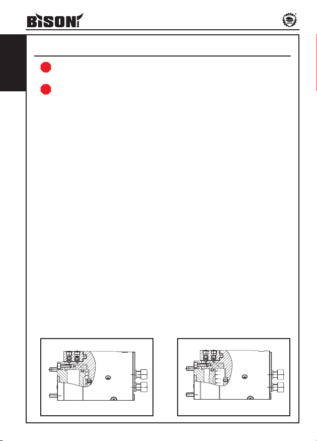
Chuck structure type 2502
The power chuck consists of a high alloy steel
body where the pneumatic cylinder connected with
a drawbar and three master jaws is mounted. The
jaws are adapted for mounting of hard top jaws.
Plain back mounting. The chuck is capable of both
internal and external clamping of the workpiece.
Power supply of the chuck through a fixed pressure
distributor placed on the adapter plate side.
The double-acting pneumatic cylinder use
the force of air pressure to move the drawbar
connected with jaws. The axial force of the
drawbar is transferred to jaws through the wedge
block system. The compressed air pressure is
transmitted through a safety control distrubutor
(mounted on the adapter plate side). A non-return
valve maintains a constant pressure flow in the
piston chamber in case of supply pressure drop.
3. cHUck strUctUre
Fig. 1
Fig. 2
Chuck component parts type 2502
NOTE: The manufacturer does not provide any pneumatic equipment, proximity switches that
work with chuck control devices as well as any parts working with the proximity switch devices.
!
Compressed air
Clamping force
Pulling force
12
78
9
5
12
13 611
3
4
1017 16 15
14
18
25
21
24 19
23
22
6
ENGLISH
4. tecHnical data
- Body -Non-return valve -O-ring (piston w/ drawbar)
- Drawbar -Control distributor -Baffle O-ring
- Master jaw -Plug (pressure control) -Adapter plate O-ring
- T-nut -Pressure distributor -O-ring (drawbar w/ cover)
- Cover -Cover screw -O-ring (baffle w/ drawbar)
- Adapter plate -Cylinder baffle screw -O-ring (adapter plate w/ cover)
- Cylinder piston -Piston screw -O-ring (piston w/ cylinder)
- Cylinder baffle -Adapter plate screw
- Valve cover -Hard top jaw screw
1
2
6
3
4
5
10
11
13
12
14
15
19
20
22
21
23
24
8
716
17
25
918
4.1 Hard top jaw clamping ranges
Fig. 13
Tab. 1
Hard top jaw clamping ranges
The jaw stroke of the master jaws and top jaws is different for different-sized chucks.
Please check whether the top jaws to clamp the workpieces are positioned correctly on the master jaws. 2/3 of the
total jaw stroke is used to clamp the workpiece, and 1/3 is for the remaining jaw stroke. Hard top jaws must only
be used in sets (marked with 1, 2, 3 part numbers).
NOTE: When mounting hard top jaws always use a torque wrench. Always tighten the mounting
bolts with correct torque adequate to a bolt size and its property class.
!
A1
J1
J2
J3
A2
A3
A4
Size A1 A2 A3 A4 J1 J2 J3
2502-160-38 7-74 67-130 115-180 163-180 18-67 66-115 114-160
2502-200-52 20-104 83-178 130-216 180-216 22-104 70-153 119-202
2502-250-65 24-124 104-207 168-266 232-266 25-122 88,5-188 152,5-252
2502-250-68 24-124 104-207 168-266 232-266 25-122 88,5-188 152,5-252
2502-315-105 64-184 142-262 206-326 270-326 64-184 128-252 192-316
2502-400-140 90-300 200-404 286-480 373-480 90-280 178-368 264-454
2502-500-230 176-402 286-510 370-596 460-600 176-402 264-490 350-576
2502-630-330 272-500 407-625 605-724 272-500 472-704
2502-800-365 326-674 434-780 600-862 326-674 494-842
2502-800-410 330-600 453-768 691-866 435-600 675-840
2502-1000-560 530-766 636-951 804-1026 530-845 698-1006

7
ENGLISH
4.2 Gripping force loss
Type 2502-160-38
Type 2502-200-52
500 1000 1500 2000 2500 3000 3500 4000
5
10
15
20
25
30
35
40
0
Max. speed [rpm]
Gripping force [kN]
500 1000 1500 2000 2500 3000 3500 4000
10
20
30
40
50
60
70
0
Gripping force [kN]
Max. speed [rpm]

8
ENGLISH
Type 2502-250-65
Type 2502-315-38
0 500 350030002500200015001000
10
110
100
90
80
70
60
50
40
30
20
Gripping force [kN]
Max. speed [rpm]
10
110
100
90
80
70
60
50
40
30
20
5000 1000 1500 2000 2500 3000
Max. speed [rpm]
Gripping force [kN]

9
ENGLISH
Type 2502-400-140
Type 2502-500-230
0 250 500 750 1000 1250
20
40
60
80
100
120
140
160
180
Max. speed [rpm]
Gripping force [kN]
0 200 400 600 800 1000 1200 1400
20
40
60
80
100
120
140
160
180
200
220
240
Gripping force [kN]
Max. speed [rpm]

10
ENGLISH
Type 2502-630-330
Type 2502-800-365
0
20
40
60
80
100
120
140
160
180
200
220
200 400 600 800 1000
Max. speed [rpm]
Gripping force [kN]
0 150 300 450 600 750
50
100
150
200
250
300
350
400
450
Gripping force [kN]
Max. speed [rpm]
11
ENGLISH
Type 2502-800-410
Type 2502-1000-560
0 150 300 450 600 750
50
100
150
200
250
300
350
400
Max. speed [rpm]
Gripping force [kN]
0 150 300 450
20
40
60
80
100
120
140
160
180
200
220
240
260
280
300
Gripping force [kN]
Max. speed [rpm]

12
ENGLISH
A4
L15
L14
D8
A1
A3
A2
A
A
B
B
G1/4''
L7
L6
L5
L1
L13
L10
M2
L11
L12
L2
L18
L8
D5
D4
D2
D1
min L3
min L4
D6
1/16''x90
L16
M3
D10
D3
A-A
M1
L9
D7
M4
L17
D9
B-B
M1
L9
B-B
2502-250-65
Type 2502 Ø160-315
4.3 Chuck technical parameters
Safety control distributor
Safety control distributor
13
ENGLISH
Typ 2502-160-38 2502-200-52 2502-250-65 2502-250-68 2502-315-105
D1 255 300 372 372 372
D2 205 248 315 315 315
D3 184 230 296 296 296
D4 155 195 235 235 235
D5 Through-hole 38 52 65 68 105
D6 168 210 254 254 315
D7 180 223,8 296 290,5 290,5
D8 70 92 117 117 154
D9 242 285 358 358 358
D10 6 6 10 10 10
L1 140,5 154 174 174 183,5
L2 136,5 150 170 170 179
L3 30,2 37,5 48,1 48 66,6
L4 38,7 47 60,8 60 79
L5 27,5 28,5 35,5 28 33,5
L6 13 13,5 17 12,5 12,5
L7 33 25 25 33 33
L8 6,5 6,5 8 6,5 6,5
L9 40 40 16 40 40
L10 24 24,5 32 32 32
L11 45 49 58 58 58
L12 77 79 104 104 104
L13 2,6 2,6 3 3 0,6
L14 38 40 45 45 52
L15 17 17 21 21 21
L16 10 10 10 10 10
L17 12 12 12 12 12
L18 101,5 110 126 126 133
A1 30° 30° 30° 30° 30°
A2 60° 60° 60° 60° 60°
A3 60° 60° 60° 60° 60°
A4 60° 60° 60° 60° 60°
M1 6xM12 6xM12 6xM10 6xM12 6xM12
M2 M12 M12 M16 M16 M16
M3 M4 M4 M5 M5 M5
M4 6xM6 6xM6 6xM6 6xM6 6xM6
Total jaw stroke 3,5 5 5 5 6
Operating pressure [MPa] 0.2/0.8 0.2/0.8 0.2/0.8 0.2/0.8 0.2/0.8
Total clamping force [kN] 43 68 87 87 100
Max. speed [rpm] 4200 3800 3000 3000 3000
Weight (without top jaws) [kg] 31,3 48,8 84,8 85,6 93,4
Moment of inertia [kgm2] 0,18 0,41 1,3 1,2 1,44

14
ENGLISH
Type 2502 Ø400-1000
A1
L15
L14
A2
L10
D8
D9
A A
G3/8''
L7
L6
L5
L1
M2
L12
L11
L13
L2L9
M1
L8
L4
L3
D5
D4
D2
D1
D6
D7
3/32''x90
D10
L16
M4
L17
M3
D3
D9
A-A
L18
D1
D6
2502-1000-560
Safety control distributor
Safety control distributor
15
ENGLISH
Typ 2502-400-140 2502-500-230 2502-630-330 2502-800-365 2502-800-410 2502-1000-560
D1 467 570 685 850 850 925
D2 400 500 610 775 775 850
D3 374 474 580 745 745 815
D4 310 415 510 700 700 700
D5 Through-hole 140 230 330 365 410 560
D6 467 570 685 850 850 1000
D7 374 474 580 745 745 815
D8 200 306 385 420 465 625
D9 448 550 666 830 830 910
D10 12 12 12 12 12 12
L1 219 229,5 249 263,5 263,5 272
L2 216,5 224 243 258 258 266
L3 94,2 141,5 191,5 210 232,1 311,6
L4 114,6 155 205,1 223,6 245,6 328,2
L5 37 37 39,5 44,5 44,5 52,5
L6 17 17 19,5 19,5 19,5 19,5
L7 26 26 33 33 33 33
L8 8 8 8 8 8 10
L9 24 26 32 27 27 27
L10 43 43 46 55 55 43
L11 75 74 70 78 78 70
L12 141,5 141,5 166,7 181,5 181,5 137
L13 0,5 3,6 4,1 4,1 4,1 4,1
L14 60 60 70 70 70 70
L15 25,5 25,5 25,5 25,5 25,5 25,5
L16 20 20 20 20 20 20
L17 20 20 20 20 20 20
L18 - - - - - 105,5
A1 20° 15° 15° 15° 15° 15°
A2 40° 30° 30° 30° 30° 30°
M1 9xM12 12xM12 12xM16 12xM16 12xM16 12xM16
M2 M20 M20 M20 M20 M20 M20
M3 M6 M6 M6 M6 M6 M6
M4 6xM8 6xM8 6xM8 6xM8 6xM8 6xM8
Total jaw stroke 7 8,5 10 10 10 10
Operating pressure [MPa] 0.2/0.8 0.2/0.8 0.2/0.8 0.2/0.8 0.2/0.8 0.2/0.8
Total clamping force [kN] 180 220 200 412 400 250
Max. speed [rpm] 1300 1300 1000 750 750 450
Weight (without top jaws) [kg] 201 285 407,5 715,8 674,9 825
Moment of inertia [kgm2] 5,6 13 28,1 74,4 72,7 132
16
ENGLISH
5. air distribUtion system
Fig. 14
NOTE: The power chuck with an integrated pneumatic cylinder use the force of compressed air
pressure (clamping and unclamping of the workpiece), can be performed at stopped spindle only.
!
Fig. 15
NOTE: The air ow delivered must be clean, undamped and correctly lubricated.
!
The compressed air that flows into the ‘clamping’
chamber of the pressure distributor causes a
deformation of the profile seal, while sealing
the connection of a distributor and chuck body,
then the air flows through the non-return valve –
resulting in:
■Connection of the cylinder ‘unclamping’
chamber with the atmosphere,
■The air flows into the cylinder ‘clamping’
chamber while displacing the piston
position - connected permanently with the
pulling sleeve, which drive the master jaw
through the wedge block system,
■The above results in clamping of the
workpiece (see Fig. 14).
The compressed air supply cut-off in the
distributor chamber is causing (see Fig. 15):
■Profiled seal returns to its original position
(seal moves out from the surface of the
chuck body),
■The non-return valve cuts-off the connection
of the supplied cylinder chamber with the
pressure distributor,
■The non-return valve keeps the pressure in
the cylinder chamber.
The workpiece is clamped and ready for machining.
5.1 Clamping of the workpiece 5.2 Unclamping of the workpiece
The compressed air that flows into the
‘unclamping’ chamber of the pressure distributor
causes a deformation of the profile seal, while
sealing the connection of a distributor and chuck
body, then the air flows through the non-return
valve – resulting in:
■Connection of the cylinder ‘clamping’
chamber with the atmosphere,
■The air flows into the cylinder ‘unclamping’
chamber while displacing the piston
position - connected permanently with the
pulling sleeve, which drive the master jaw
through the wedge block system,
■The above results in unclamping of the
workpiece.
The compressed air supply cut-off in the
distributor chamber is causing:
■Profiled seal returns to its original position
(seal moves out from the surface of the
chuck body),
■The non-return valve cuts-off the connection
of the supplied cylinder chamber with the
pressure distributor,
■The non-return valve keeps the pressure in
the cylinder chamber.
The workpiece is unclamped.

17
ENGLISH
6. installation on tHe latHe
The lathe should be equipped with a special ring or
brackets, supporting the distributor in centric and
non-contact position with the chuck, as well as the
adapter plate (for chuck mount). The operator should
get these elements by himself or order.
Stiffly and permanently mount the ring or brackets
onto the lathe spindle or spindle bearing cover; the
adapter plate on the spindle end. The adapter plate
requires two I.D. holes of Ø14mm for the safety valve
pin output (the holes spacing according to drawings
provided in this manual).
After installation, the ring or brackets, and adapter
plate should meet the conditions indicated in Fig. 16.
..
Fig. 16
6.1 Preparing the lathe
6.2 Preparing the chuck for mounting
Chuck adapter plate and distributor bracket
The workstation should be equipped with the
compressed air connection, that contains a connecting
block and shut-off valve (block valve).
The control system and tooling operator should get
by himself or order.
For controlling, use the 2-way 3-position valve
located in a mid-position, connecting the chamber to
the atmosphere. (Fig. 17).
4 2
3 1
Fig. 17
Control valve scheme
NOTE: The manufacturer does not provide any pneumatic equipment, proximity switches that work
with chuck control devices as well as any parts working with proximity switch devices.
!
■open the package,
■check, if the delivered product is fully completed,
■dismount the distributor from the chuck,
■lift the chuck up via an eyebolt and remove from
the package,
■place the chuck down in a position preventing
chuck motion,
To mount the chuck on the lathe, please proceed as follows:
NOTE: Never place the chuck onto jaws!
!
■the protective lubricant needs to be removed
carefully. Pay attention while clearing out the chuck
seat as well as distributor seat,
,
■lift the chuck up via hoist and an eyebolt,
■place the distributor onto the chuck,
■center the spindle towards to chuck, so that
the safety valve pin catches the adapter
plate I.D. holes of Ø14mm,
■mount the chuck to the adapter plate,
■mount the pressure distributor,
■check, whether during the rotation the chuck
is not rubbing the pressure distributor, if it
does then needs to be centered,
■when dismounting from the lathe, please
proceed in the reverse order.

18
ENGLISH
7. dismoUnting and moUnting
6.3 Preparing the chuck for operating
■on the control arbors, mount the parts that work
with proximity switches,
■mount the proximity switches that work with chuck
control devices,
■while using the exible hoses, connect the
distributor together with a connecting block,
■the jaw mounting bolts must be tightened to the
specied torque,
To get the chuck ready for operating, please proceed as follows:
■perform several clamp/ unclamp test
operations,
■it is recommended to check the jaws
clamping force and adjust air pressure to
working conditions,
■while replacing the jaws, clean the teeth
surfaces thoroughly.
NOTE: After mounting the control tooling and device into the chuck of 2502 type, the machine
should meet the essential requirements complied in the Machinery Directive 98/37/ WE.
According to the Directive, the manufacturer is the party who has mounted the control tooling and
device and is obliged to issue the WE declaration of conformity.
!
NOTE: Any chuck operation work must be performed after previous pressure alignment with the
atmosphere in the chuck chambers.
!
■disconnect the air supply from the chuck,
■disconnect the chuck air supply hoses,
To align the pressure with the atmosphere in the chuck chambers, please proceed as follows:
■align the pressure with the atmosphere in the chuck
chambers,
■dismount the chuck from the lathe via hoist and
an eyebolt,
■dismount the top jaws,
■dismount the pressure distributor,
■place the chuck down in a position preventing
chuck motion,
7.1. Dismounting the chuck
NOTE: Never place the chuck onto jaws!
!
■dismount the control pressure distributor,
■unscrew the valve cover (9),
■dismount the non-return valve (10),
■place the chuck with jaws upside down on
a special pad, so the jaws can relocate easily,
■unscrew the adapter plate screws (17),
■dismount the adapter plate screws (6),
■unscrew the piston screws (16)
■dismount the cylinder piston (7),
■unscrew the cylinder bafe screws (15),
■dismount the cylinder bafe (8),
■dismount the drawbar (2),
■dismount the master jaws (3).
■unscrew the cover screws (14),
■dismount the cover (5),
■loosen the pressure control plug (12),
■loosen the valve cover (9).
To dismount the chuck, please proceed as follows:
NOTE: When using the special top jaws, the operator should check on (determine) the correct
jaw clamping force.
!
This manual suits for next models
11
Table of contents
Other Bison Industrial Equipment manuals


Popular Industrial Equipment manuals by other brands


ABB
ABB Relion 670 series Applications manual

Reef Octopus
Reef Octopus Neck Cleaner-110 quick start guide

RF SOLUTIONS
RF SOLUTIONS MAINSLINK quick start guide

schmersal
schmersal SLC 425I operating instructions

Siemens
Siemens SIVACON 8PS BD01 installation instructions

Rittal
Rittal RiLine Compact Assembly instructions