Robert Juliat JALOUSIE 2 User manual

Robert Juliat S.A.S. Route de Beaumont, F60530 Fresnoy-en-Thelle - phone : +33 (0)3 44 26 51 89 - fax : +33 (0)3 44 26 90 79 - info@robertjuliat.fr
Robert Juliat U.S.A. 48 Capital Drive, Wallingford, CT 06492 –USA - phone : (203) 294 0481 - fax : (203) 294 0482 - info@robertjuliatamerica.com
JALOUSIE 2
Specialist products
JAL2 - Ø206 V4
JAL2 - Ø280 V6
JAL2 - Ø340 V6
JAL2 - Ø404 V4
DMX-controlled motorised shutters
Valid since: 17/11/11
Software version: V2.06
DN40977200-A
Manual

- 2 -
Summary :
1User’s instructions ............................................................................................................................ 3
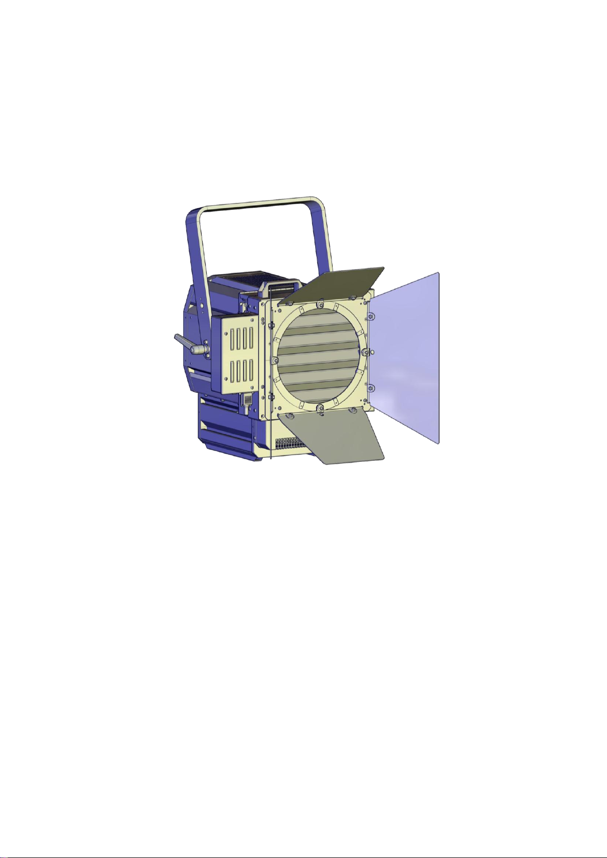
2Presentation ..................................................................................................................................... 4
2.1 JALOUSIE2 ................................................................................................................................ 4
2.2 Included accessories.................................................................................................................. 4
2.3 Optional accessories.................................................................................................................. 4
3Installation ........................................................................................................................................ 5
3.1 Mechanics .................................................................................................................................. 5
3.1.1 Adaptation kit..................................................................................................................... 5
3.1.2 Operating position.............................................................................................................. 6
3.1.3 Safety cable....................................................................................................................... 6
3.1.4 Optional accessories holder .............................................................................................. 7
3.1.5 Optional local potentiometer.............................................................................................. 7
3.2 Electrical..................................................................................................................................... 8
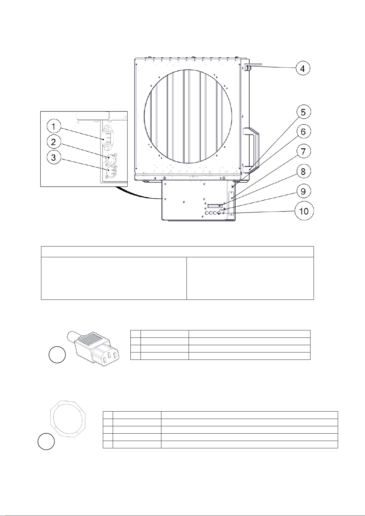
3.2.1 Connections :..................................................................................................................... 8
3.2.2 Power supply ..................................................................................................................... 8
3.2.3 DATA ................................................................................................................................. 8
4Operation.......................................................................................................................................... 9
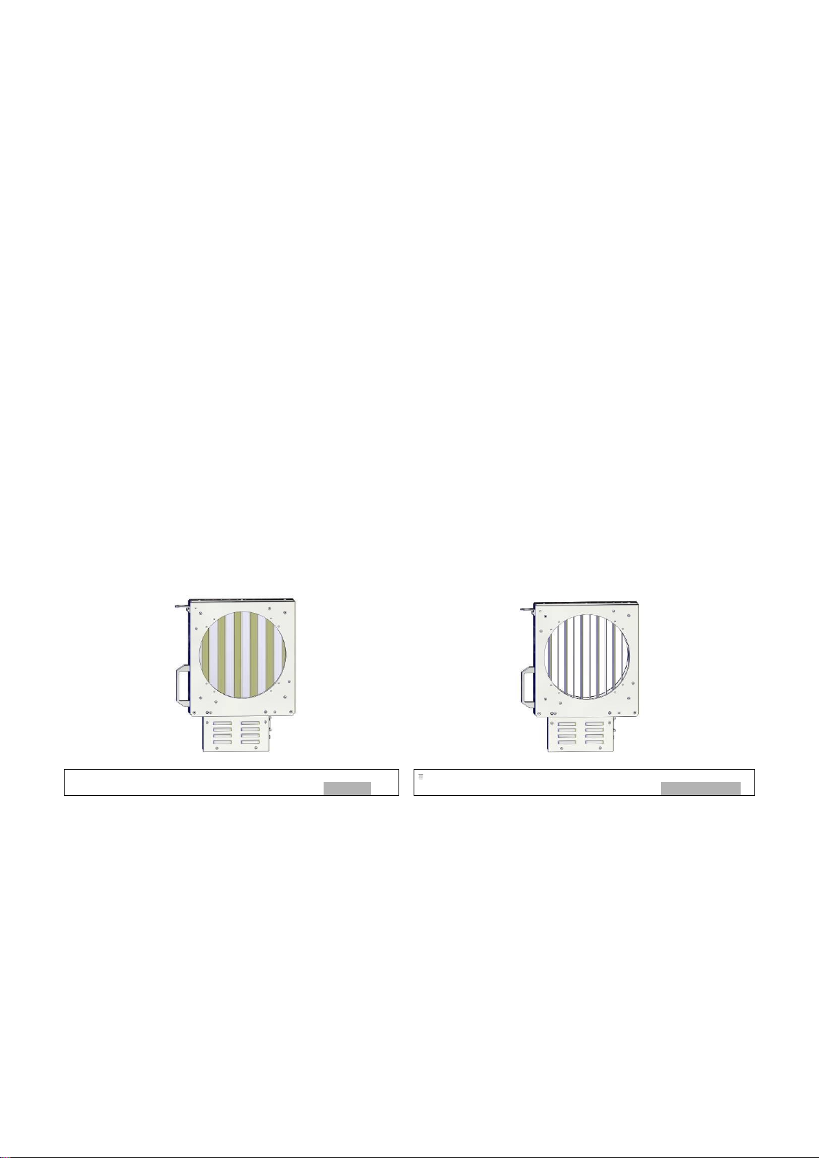
4.1 Dimmer shutter........................................................................................................................... 9
4.2 Control board............................................................................................................................ 10
4.2.1 Controls............................................................................................................................ 10
4.2.2 Display............................................................................................................................. 10
4.2.3 Menus and parameters.................................................................................................... 11
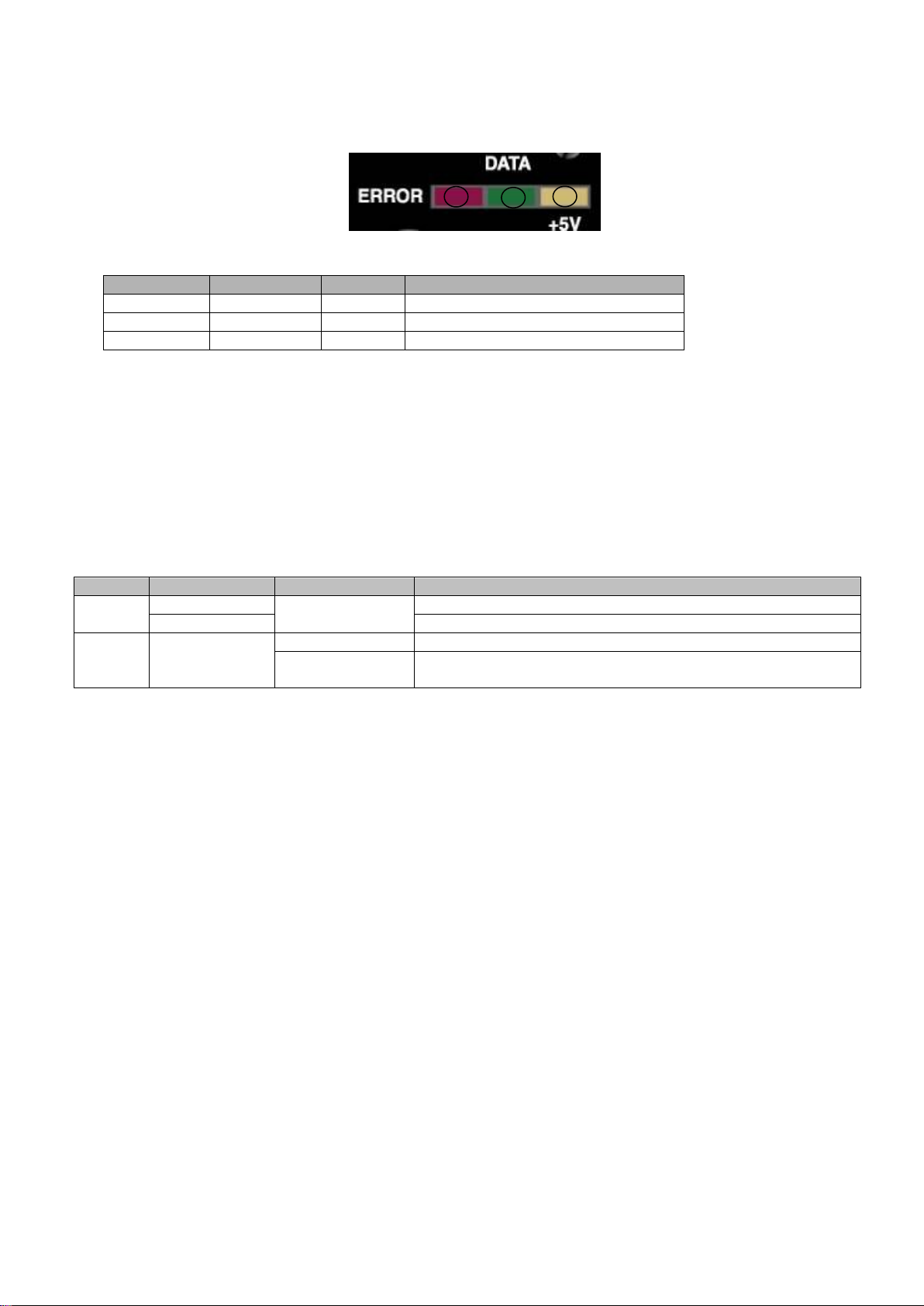
4.2.4 LED feedback .................................................................................................................. 13
4.2.5 RESET............................................................................................................................. 13
4.3 DMX remote control.................................................................................................................. 13
5Servicing......................................................................................................................................... 14
5.1 Preventative maintenance........................................................................................................ 14
5.1.1 Frequency........................................................................................................................ 14
5.1.2 General cleaning.............................................................................................................. 14
5.1.3 General visual check ....................................................................................................... 14
5.1.4 Wiring & Connections ...................................................................................................... 14
5.2 Blades position adjustment ...................................................................................................... 14
5.3 Software update ....................................................................................................................... 14
5.4 Analysis .................................................................................................................................... 14
5.5 Spare parts............................................................................................................................... 15
6Troubleshooting.............................................................................................................................. 15
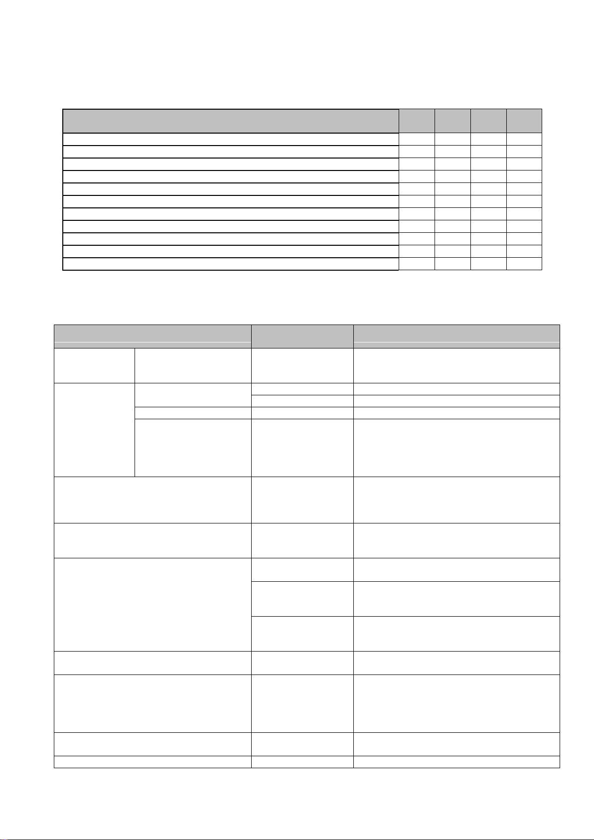
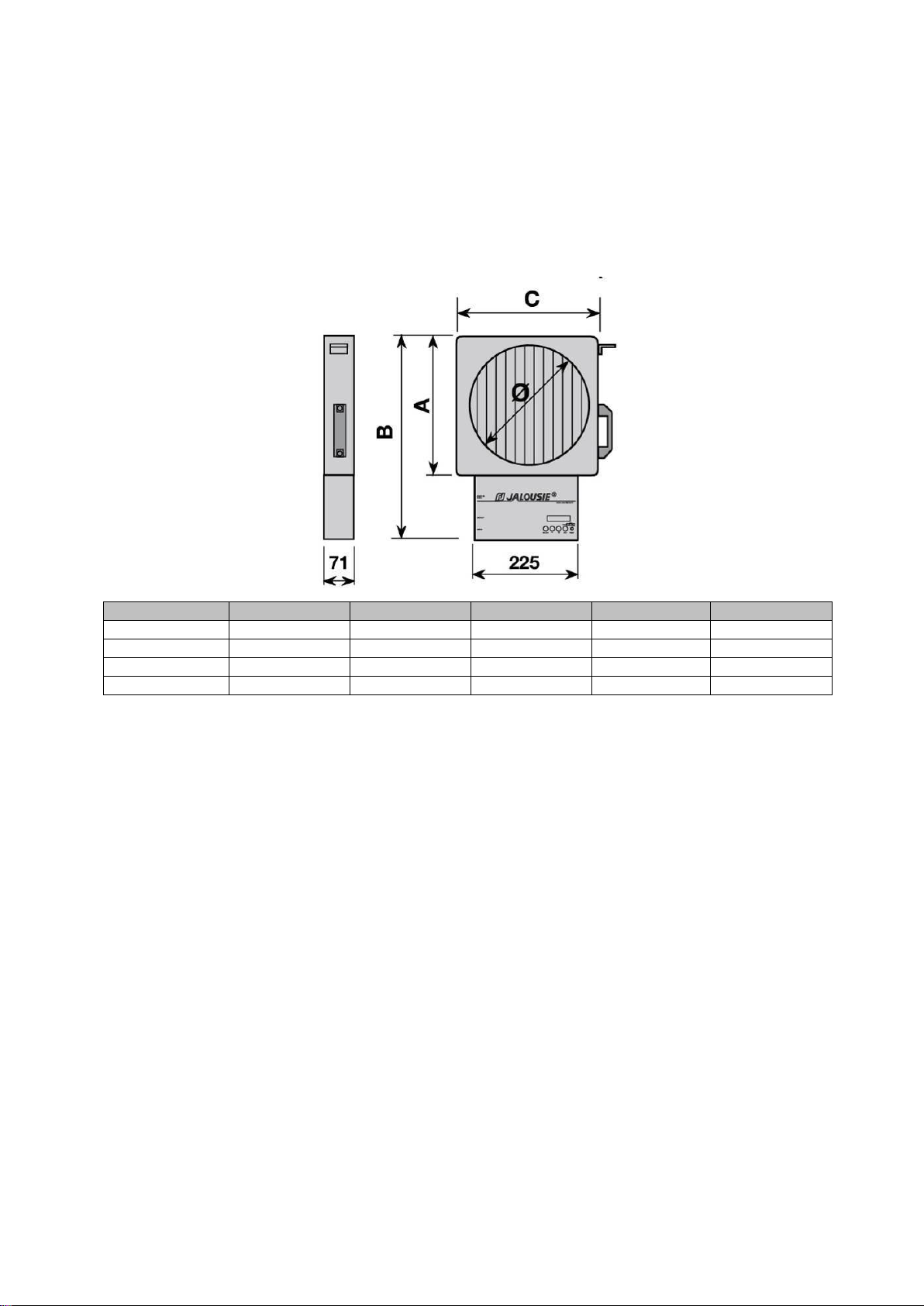
7Technical specifications ................................................................................................................. 16
Robert Juliat reserve the right to change
or alter any of the items detailed on this page,
to increase or improve manufacturing techniques without prior notice.

- 3 -
1 User’s instructions
GENERAL INSTRUCTIONS
1 Not for residential use.
2 These fixtures must only be serviced by a qualified technician.
3 In addition to the instructions indicated on this page, relevant health and safety requirements of the appropriate EU
Directives must be adhered to at all times.
4 This fixture is in compliance with section 17 - Lighting appliance for theatre stages, television, cinema and photograph
studios. Standards NF EN 60598-1 and NF EN 60598-2-17.
5 This fixture is rated as IP20, and is for indoor use only.
UNIT
6 Warning: disconnect from mains supply before servicing.
7 Ensure fixture is correctly mounted on an appropriate support.
8 Unit must be secured by a safety cable of suitable length.
9 Safety bonds or cables must be securely attached to the unit and be as short as possible, or rolled up as necessary, to
minimise travel distance should the unit be dislodged.
10 Movable accessories (barn doors, spill rings etc.) must also be secured with a suitable safety cable or bond at the front of
the unit.
11 The combined weight of both the unit and the accessories must be considered when choosing the load-bearing capability
of safety cable or bond.
12 WARNING: unit becomes hot during use. Allow fixture to cool before servicing.
13 Do not tamper with design of unit nor any of its safety features.
14 Tighten electrical mains cable connections regularly and replace with one of identical specification if damaged.
15 Do not connect to "electronic output" such as dimmer or static relay.
16 Maximum surrounding temperature: t°a=40°C.
17 Not for outdoor use. Do not cover. Do not permit fixture to get wet.
18 To avoid overheating, do not obstruct air vents.
19 Regularly remove dust.
PLEASE NOTE :
These products have been built to conform to European standards relating to professional lighting equipment.
Any modification made to our products will void the manufacturers' warranty.

- 4 -
2 Presentation
2.1 JALOUSIE2
2.2 Included accessories
2.3 Optional accessories
Functions :
1. Power connection (IEC C14 connector)
2. DMX IN (XLR5 connector)
3. DMX OUT (XLR5 connector)
4. Safety bond attachment point
5. Handle
6. Optional local potentiometer
7. Identification plate
8. Setup display
9. LED feedback
10. Setup buttons
Reference
Description
1
COU0003265
IEC C13 power connector
Reference
Description
Local potentiometer
1
PAOA270601
JAL2/Ø280 adaptation kit for Robert Juliat 312LF and 326LFV
PAOA340902
JAL2/Ø340 adaptation kit for Robert Juliat 312LF and 326LFV
Adaptations for other models: please contact your distributor
1
1

- 5 -
Lantern’s accessories
holder must be locked
3 Installation
3.1 Mechanics
3.1.1 Adaptation kit
The use of an adaptation kit to use the JALOUSIE2 on Fresnel lanterns is necessary. The
JALOUSIE2 can be delivered with the mounting plate fitted on the JALOUSIE2. Contact your
distributor for compatibility on existing models.
Please refer to the adaptation kit manual for installation.
Step 2
Step 3
Step 4
Step 1
Step 3

- 6 -
3.1.2 Operating position
For better results, JALOUSIE2 blades have to be perpendicular to the arc of the lamp:
3.1.3 Safety cable
JALOUSIE2 must be secured with appropriate safety
cable (not provided) from attachment point A to
lantern’s attachment point B.
Overheating

- 7 -
3.1.4 Optional accessories holder
JALOUSIE2 adaptation kit includes front accessories holder for barndoors, gel frame,
scroller…
JALOUSIE2 comes with a front accessory holder having the same specifications as the one
on the luminaire*. *except for JAL2/Ø340 adaptation kit for Robert Juliat 312LF and 326LFV
3.1.5 Optional local potentiometer
Contact your local RJ service centre.

- 8 -
3.2 Electrical
3.2.1 Connections :
3.2.2 Power supply
JALOUSIE2 must be connected directly to AC power.
Do not connect JALOUSIE2 to dimmer.
Automatic power detection.
Fuse: internal (PSU) –time-delay 3.15A.
Recommended circuit breaker: 6A –C curve
Voltage
Frequency
Input power
Connectors
Recommended cable (not provided)
90 250 V
50/60 Hz
40 W
IEC C13/C14
H05 RRF 3G 0.75
3.2.3 DATA
Remote control uses USITT DMX 512-A protocol.
Input and output connections are using XLR 5-pin
connectors.
PIN #
DMX
Description
1
Foil & Braided Shield
2
DMX (-)
1st conductor of 1st twisted pair
3
DMX (+)
2nd conductor of 1st twisted pair
4
1st conductor of 2nd twisted pair
5
2nd conductor of 2nd twisted pair
Symbol
PIN
L
live
N
neutral
W
Earth (ground)

- 9 -
4 Operation
4.1 Dimmer shutter
JALOUSIE2 enables to control the light intensity of discharge fresnel luminaires by a
mechanical system. The rotating blades in front of the lighting unit stop an increasing among
of light coming from the lamp.
When JALOUSIE2 is powered up, motor reset procedure is done.
The position of the blade goes from 0% (blades closed –no light output) to 100% (blades
open –maximum light output).
Control of the aperture can be done locally through the display and optional potentiometer or
remotely by using USITT DMX 512 protocol. Choice of LTP or HTP merger is possible in
setup menu.
Dimming curves can be selected in setup menu:
oLM: Linear Motor
oLL: Linear Light
Mounting a mechanical shutter on a spotlight will affect the apparent output of the
luminaire so it is strongly recommended that all precautions be taken during the design
of the light plot. ROBERT JULIAT shall not be responsible for reduced lighting levels
and aperture that may result from the use of a JALOUSIE2 shutters.
0%
50%
100%

- 10 -
4.2 Control board
4.2.1 Controls
4.2.2 Display
Name
Function
1
display
Display
2
select
Enter the current menu option and/or valid
3
-
Scrolls through menus and/or Decrease blinking data value
4
+
Scrolls through menus and/or Increase blinking data value
5
exit
Exit the current menu option and/or go back
6
reset
Hard CPU reset
7
Data
DMX LED feedback (Cf. 4.3)
1
/
6
C
H
A
N
N
E
L
h
*
1
P
O
S
I
T
I
O
N
(
d
)
0
%
Function
Values
1
Merger mode
“h” = HTP
“l” = LTP
2
Active value
“d” = DMX
“l” = local
“a” = analog
3
Opening
Value depending on display mode
4
Display mode
“%” = pourcent : 0 100%
“h” = hexadecimal : 0 ff
“b” = visual mode
5
DMX address
0 512
6
Dimming curve
“ ” = LM: Linear Motor
“*” = LL: Linear Light
1
2
3
4
5
6

- 11 -
Select
-
+
Select
Select
-
+
-
+
-
+
Select
-
+
Select
Select
-
+
Select
Select
Select
-
+
-
+
Select
4.2.3 Menus and parameters
Access to DMX address
*If 512 channels detected
Access to local value
Analog value
Value of the optional local potentiometer.
Motor reset
Press select to launch the motor self calibration
procedure.
Access to unit parameters
Display mode of the values
Optional local potentiometer activation
Brake function activation (DMX channel 3)
for smooth movements
1
/
6
C
H
A
N
N
E
L
h
1
P
O
S
I
T
I
O
N
(
d
)
0
%
Value (-/+)
Function
1
510*
DMX address
C
H
A
N
N
E
L
1
2
3
P
.
0
%
0
%
0
%
2
/
6
C
H
A
N
N
E
L
h
1
L
O
C
A
L
V
A
L
U
E
0
%
C
H
A
N
N
E
L
1
L
O
C
A
L
V
A
L
U
E
0
%
Value (-/+)
Function
0
100%
Local value
3
/
6
C
H
A
N
N
E
L
h
1
A
N
A
L
O
G
V
A
L
U
E
O
F
F
%
4
/
6
C
H
A
N
N
E
L
h
1
M
O
T
O
R
R
E
S
E
T
C
O
N
F
I
R
M
M
O
T
O
R
R
E
S
E
T
5
/
6
C
H
A
N
N
E
L
h
1
P
R
E
F
E
R
E
N
C
E
S
1
/
8
P
R
E
F
E
R
E
N
C
E
S
D
I
S
P
L
A
Y
D
E
C
1
/
8
P
R
E
F
E
R
E
N
C
E
S
D
I
S
P
L
A
Y
D
E
C
Value (-/+)
Function
DEC
decimal : 0 100%
HEX
hexadecimal : 0 ff
BAR
visual mode
2
/
8
P
R
E
F
E
R
E
N
C
E
S
A
N
A
L
O
G
V
A
L
U
E
O
F
F
1
/
8
P
R
E
F
E
R
E
N
C
E
S
A
N
A
L
O
G
V
A
L
U
E
O
F
F
Value (-/+)
Function
OFF
local potentiometer deactivated
ON
local potentiometer activated
3
/
8
P
R
E
F
E
R
E
N
C
E
S
B
R
A
K
E
O
F
F
3
/
8
P
R
E
F
E
R
E
N
C
E
S
B
R
A
K
E
O
F
F
Value (-/+)
Function
OFF
Brake deactivated
ON
Brake activated
Select
Select

- 12 -
-
+
Select
Select
Select
Select
-
+
Select
Select
Select
Select
Select
-
+
Select
-
+
-
+
Language mode
Choice of :
Francais / English / Deutsch / Español / Italiano
Merger mode
(for local, analog and DMX values)
Light curve mode
Blades position adjustment (close position)
Cf. 5.Service for adjustment procedure.
Blades position adjustment (open position)
V2.6 software version only
Cf. 5.Service for adjustment procedure.
Information
Data protocol detected / numbers of channels
Software version
ROBERT JULIAT website
ROBERT JULIAT contact Email
ROBERT JULIAT phone number
Unit temperature (degrees celsius)
4
/
8
P
R
E
F
E
R
E
N
C
E
S
L
A
N
G
U
A
G
E
E
N
G
L
I
S
H
4
/
8
P
R
E
F
E
R
E
N
C
E
S
L
A
N
G
U
A
G
E
E
N
G
L
I
S
H
5
/
8
P
R
E
F
E
R
E
N
C
E
S
M
O
D
E
H
T
P
5
/
8
P
R
E
F
E
R
E
N
C
E
S
M
O
D
E
H
T
P
Value (-/+)
Function
HTP
Highest Takes Precedence
LTP
Lastest Takes Precedence
6
/
8
P
R
E
F
E
R
E
N
C
E
S
C
U
R
V
E
L
M
1
6
b
i
t
s
6
/
8
P
R
E
F
E
R
E
N
C
E
S
C
U
R
V
E
L
M
1
6
b
i
t
s
Value (-/+)
Function
LM
Linear Motor
LL
Linear Light
7
/
8
P
R
E
F
E
R
E
N
C
E
S
Z
E
R
O
P
O
S
I
T
I
O
N
4
5
0
7
/
8
P
R
E
F
E
R
E
N
C
E
S
Z
E
R
O
P
O
S
I
T
I
O
N
4
5
0
8
/
8
P
R
E
F
E
R
E
N
C
E
S
M
A
X
P
O
S
I
T
I
O
N
3
2
4
6
7
8
/
8
P
R
E
F
E
R
E
N
C
E
S
M
A
X
P
O
S
I
T
I
O
N
3
2
7
6
7
6
/
6
C
H
A
N
N
E
L
h
1
P
R
O
T
O
C
O
L
D
M
X
5
1
2
1
/
5
I
N
F
O
R
M
A
T
I
O
N
V
E
R
S
I
O
N
V
2
-
0
6
2
/
5
I
N
F
O
R
M
A
T
I
O
N
w
w
w
.
r
o
b
e
r
t
j
u
l
i
a
t
.
f
r
3
/
5
I
N
F
O
R
M
A
T
I
O
N
i
n
f
o
@
r
o
b
e
r
t
j
u
l
i
a
t
.
f
r
4
/
5
I
N
F
O
R
M
A
T
I
O
N
P
h
:
+
3
3
(
0
)
3
4
4
2
6
5
1
8
9
5
/
5
I
N
F
O
R
M
A
T
I
O
N
t
e
m
p
e
r
a
t
u
r
e
6
5
°
C
Select
Select
Select
Select

- 13 -
4.2.4 LED feedback
LED
Name
Status
Description
1 - red
ERROR
on
Data error
2 - green
DATA
on
DMX512 detected
3 - yellow
+5V
on
CPU power OK
4.2.5 RESET
Push RESET button, then SELECT to confirm
Hard reset of the system is done (equivalent to power-on reset)
4.3 DMX remote control
DMX Channel
DMX value
Function
Dimmer
1
0 - 65535
Dimmer (High Byte)
2
Dimmer fine (Low Byte)
Mode
control*
3
0
BRAKE off : very fast movement (>5 flash/s)
1- 255
BRAKE on:
fast movement (2 flash/s) smooth movement (0.01 flash/s)
* if Brake function activated in PREFERENCES menu.
If BRAKE function is not activated, blades movement will be fast but not accurate. Light spills
can be seen when blades are closed.
For smooth continuous movements, BRAKE function has to be activated. Speed can be
controlled from 1 to 255.
BRAKE function is not recommended if mixing both JALOUSIE2 with current V2-06 version and
JALOUSIE2 with previous software version, otherwise blades movement will not be
synchronised.
1
2
3

- 14 -
5 Servicing
5.1 Preventative maintenance
5.1.1 Frequency
General maintenance should be performed at least 3 times a year, or more frequently if the equipment
is operated in adverse conditions (smoke, heat, humidity, touring, etc.).
5.1.2 General cleaning
Remove dust from the unit (air vents, printed circuit boards, etc.).
5.1.3 General visual check
No trace of heat.
No loose contacts.
No missing parts.
Tighten mechanical assemblies (screws, bolts and nuts, ground connections, etc.).
5.1.4 Wiring & Connections
Cable terminal screw: Visually check, tighten if necessary (do not over tighten).
Electronic connectors: Visually check the position and the locking clips (if needed).
5.2 Blades position adjustment (V2.04 software only)
Adjustment of the minimum position (0%) and the maximum position (100%). Positions need to be
adjusted if light spills at 0% are detected or if blades have been changed.
DMX must be disconnected. Local value must be used to open or close the blades.
BRAKE function must be deactivated in PREFERENCES menu.
Position can be adjusted in PREFERENCES menu by pressing +and –buttons:
7
/
8
P
R
E
F
E
R
E
N
C
E
S
Z
E
R
O
P
O
S
I
T
I
O
N
4
5
0
8
/
8
P
R
E
F
E
R
E
N
C
E
S
M
A
X
P
O
S
I
T
I
O
N
3
2
7
6
7
Minimum position :
Value must be changed in order to have
visually the blades in contact.
Maximum position :
Value must be changed in order to have
visually the blades at 90°.
5.3 Software update
Contact your local RJ service centre.
5.4 Analysis
If there a problem remains after the Troubleshooting procedure (Cf. 6.), contact local RJ service centre
with the following information:
Model and serial number of the product.
Software version.
Description of the problem.

- 15 -
5.5 Spare parts
Code
Description
JAL2
Ø206
JAL2
Ø280
JAL2
Ø340
JAL2
Ø404
DJ30413301
SHUTTER BLADE
X
DJ30413302
SHUTTER BLADE
X
DJ30413303
SHUTTER BLADE
X
DJ30413304
SHUTTER BLADE
X
CC40723901
CPU MOTOR CARD, REF. RJ407239-4A4
X
CC40723907
CPU MOTOR CARD, REF. RJ407239-4G1
X
X
CC40723904
CPU MOTOR CARD, REF. RJ407239-4D4
X
CC40685101
KEYBOARD CARD - LCD DISPLAY REF. RJ406851-2A1
X
X
X
X
ME20024003
POWER SUPPLY 30W-24V DC
X
X
X
X
ME19024003
MOTOR FOR JALOUSIE DIMMING SHUTTER
X
ME19024004
MOTOR FOR JALOUSIE2 DIMMING SHUTTER
X
X
X
6 Troubleshooting
SYMPTOMS
POSSIBLE
CAUSES
SOLUTIONS
Impossible to
command the
unit
+5V orange LED is off
No power
Check power supply
Failure to
command the
unit by DMX
DATA green LED is off
DMX data wiring
Check connectors and data cable
DMX protocol
Check data protocol detected in menu 6/6
DATA green LED is on
DMX address
Check DMX address of the 1st channel
DATA green LED is on
–blades are open
Local value or
potentiometer at
100% and HTP
merger mode
activated
Change local values to 0% and/or change
merger mode to LTP in menu 5/6
Impossible to close the blades by DMX
completely
Local value or
potentiometer > 0%
and HTP merger
mode activated
Change local values to 0% and/or change
merger mode to LTP in menu 5/6
Impossible to close the blades by local
value completely (display or
potentiometer)
DMX value > 0%
and HTP merger
mode activated
Change DMX value to 0% and/or change
merger mode to LTP in menu 5/6
When using several units, dimming are
not synchronized
Different dimming
curves
All the units must have the same dimming
curve (menu 5/6)
BRAKE function
on/off
BRAKE function must be either all on or all
off on all units. Mode control DMX channel
must have the same value.
Different software
version
If one of the units doesn’t have V2.06
software version, BRAKE function must be
disabled on all units (menu 5/6)
Light spill can be seen at 0%
Blades position
adjustment
See 5.2 for adjustment procedure
Displayed message: “Position (!) DFT%”
Mechanism problem
or external
components
blocking the rotation
of the blades
Unplug the power and remove external
components blocking the system. Plug the
power back to reset the system. If problem
still remains: check the rotation manually
with the unit unplugged
DMX LED feedback is red even if DMX
unplugged
Faulty data driver
component
Contact local RJ service centre to change
the component

- 16 -
7 Technical specifications
Dimensions and weight*:
Ref.
Ø
A
B
C
Weight*
JAL2 - 206
206
298
415
263
3Kg
JAL2 - 280
280
372
487
338
4,3Kg
JAL2 - 340
340
432
545
416
5,5Kg
JAL2 - 404
404
493
612
494
6,9Kg
(*) Without adaptation
This manual suits for next models
4
Table of contents
Popular Indoor Furnishing manuals by other brands

Prospect Designs
Prospect Designs Adjustable Tilt in Space Assembly and use instructions

atmosphera
atmosphera 157149 instruction sheet

Hooker Furniture
Hooker Furniture 5070-75510 Assembly instruction

Birlea
Birlea CROXLEY BED Assembly instructions

Kesseböhmer
Kesseböhmer LifeUP You manual

MAZIN FURNITURE
MAZIN FURNITURE B45 quick start guide

Songmics
Songmics LPC111 manual

Lutron Electronics
Lutron Electronics Sivoia QED Roller 64 installation instructions

Swing-N-Slide
Swing-N-Slide NE 4273 Assembly instructions

Kambrook
Kambrook KCL10 Series instruction manual

Teknik
Teknik Chunky 4 Shelf Bookcase 5422095 Instruction booklet

Pacific Casual
Pacific Casual 13D-009-3BAL Assembly instructions