Robots and Design Maxx DS200 Series User manual

USER GUIDE
MAXXDS200 series
www.stomshop.pro

Computer and Robotics Aided Manufacturing
2
Copyright © 2016 Robots and Design Co., Ltd.
This manual is used for MAXXDS200 series only.
Please contact the address below for any questions.
AddressPangyo-ro 700, E-707, Seongnam-City, Gyunggi-do, Korea 13516
Tel+82-31-708-2684
Fax+82-31-706-9093
E-mail[email protected]
Manual provided with the machine may not include the latest information.
www.stomshop.pro

Computer and Robotics Aided Manufacturing
3
CONTENTS
1. EPNC Installation............................................................................................................ 5
2. Description of EPNC....................................................................................................... 6
2.1 Initialization window..................................................................................................... 6
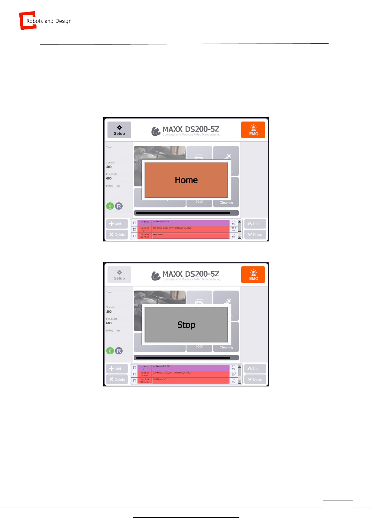
2.2 Main window................................................................................................................ 7
2.2.1 Functions of main window..................................................................................... 8
2.2.1.1 Operational setting & EMO............................................................................. 8
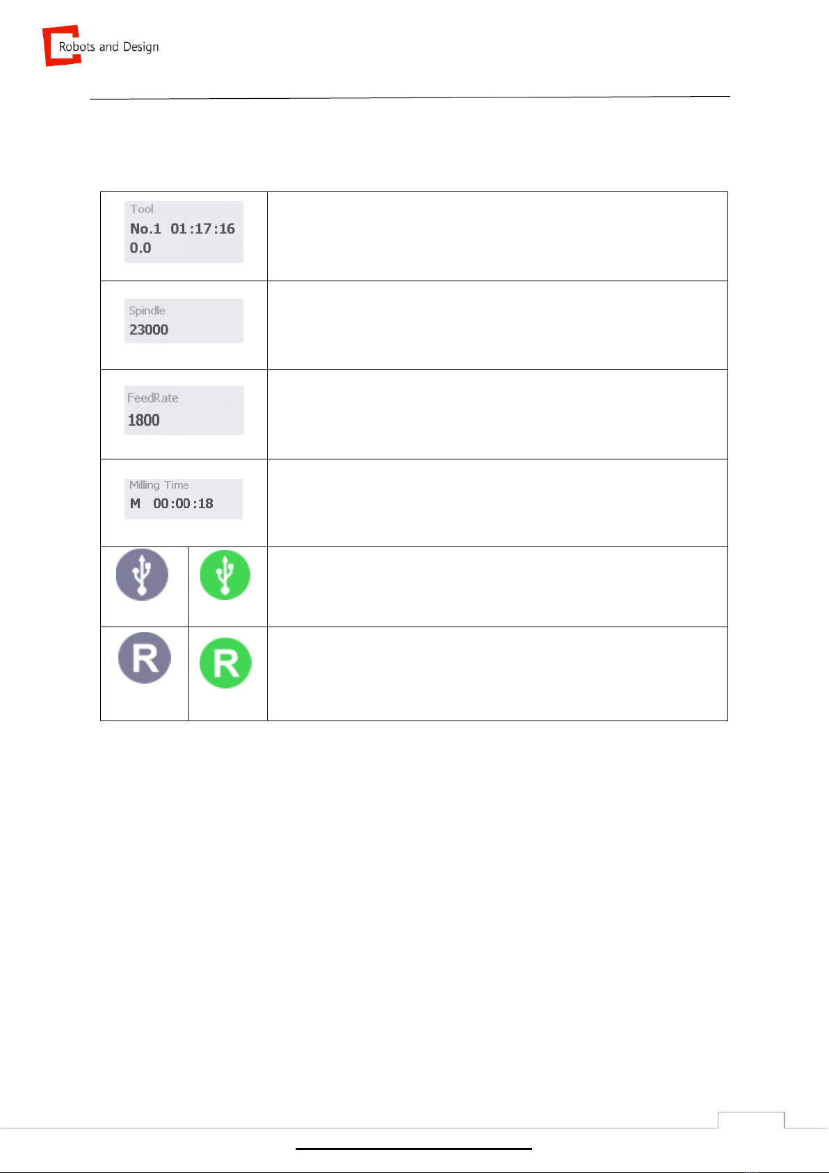
2.2.1.2 Machine status............................................................................................... 9
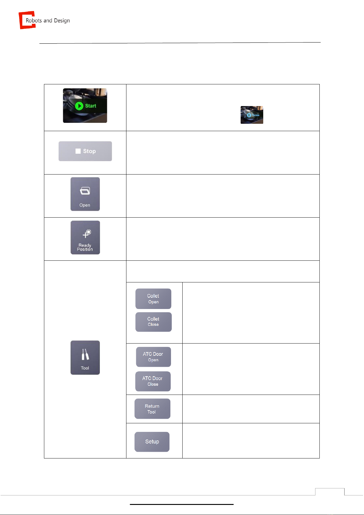
2.2.1.3 Commonly used functions ............................................................................ 10
2.2.1.4 NC file .......................................................................................................... 12
2.3 Setup......................................................................................................................... 14
2.3.1 Entering setup..................................................................................................... 14
2.3.2 Teaching............................................................................................................. 15
2.3.2.1 Functions of teaching ................................................................................... 15
2.3.2.2 Coordinate offset & Teaching point ............................................................. 16
2.3.2.3 Option........................................................................................................... 18
2.3.2.4 Jog ............................................................................................................... 19
2.3.2.5 Auto Calibration............................................................................................ 21
2.3.3 Tool..................................................................................................................... 22
2.3.4 Term................................................................................................................... 24
2.3.5 Option................................................................................................................. 25
2.3.6 I/O....................................................................................................................... 27
2.3.7 Log...................................................................................................................... 28
2.3.8 System................................................................................................................ 29
3. Milling ............................................................................................................................ 30
3.1 Machine power.......................................................................................................... 30
www.stomshop.pro

Computer and Robotics Aided Manufacturing
4
3.2 Milling preparation ..................................................................................................... 30
3.2.1 Mounting workpiece............................................................................................ 30
3.2.1.1 Disc type ...................................................................................................... 30
3.2.1.2 Pin type........................................................................................................ 31
3.2.1.3 Pre-milled bar (R & D type)........................................................................... 32
3.2.2 Tool..................................................................................................................... 34
3.2.2.1 Tool specification.......................................................................................... 35
3.2.3 Starting NC file.................................................................................................... 35
4. Maintenance.................................................................................................................. 36
4.1 Maintenance precautions........................................................................................... 36
4.2 Daily maintenance..................................................................................................... 37
4.2.1 Cleaning.......................................................................................................... 37
4.2.2 Dummy tool..................................................................................................... 38
4.3 Periodical maintenance ............................................................................................. 39
4.3.1 Replacing consumable parts ........................................................................... 40
4.3.2 Spindle warm-up ............................................................................................. 41
4.3.3 Spindle cleaning.............................................................................................. 44
4.3.4 Auto calibration................................................................................................ 45
4.3.5 Collet tightening............................................................................................... 52
5. Trouble shooting........................................................................................................... 53
5.1 Restart milling............................................................................................................ 53
5.2 Air pressure sensor setting........................................................................................ 56
5.3 Removing ATC push limit .......................................................................................... 58
www.stomshop.pro

Computer and Robotics Aided Manufacturing
5
1. EPNC Installation
Program Installation
To install the program, copy PNC folder. PNC folder is organized as below.
①<Bin> Folder
<Bin> contains necessary DLL files to execute Pnc.exe and the program. Below is the
description of main executable file and DLL.
File name
Description
Remarks
PNC.exe
PNC Program file
PComm32.dll
DLL files to manage Pmac Controller
①<Config> Folder
<Config> contains necessary setting files to execute PNC program. Detailed description for
each setting file is in “8. Config file” in <Config> folder.
②<Log> Folder
<Log> is log files of machine. It is saved in Pnclog.db file. To check contents of log files,
special viewer is required.
③<NcFiles> Folder
<NcFiles> is to save NC files for milling. It can be used to copy files from outside.
④<Resource> Folder
<Resource> is to save resources that will be used in the program. It is not allowed to delete
or change names of files saved in the folder.
www.stomshop.pro

Computer and Robotics Aided Manufacturing
6
2. Description of EPNC
2.1 Initialization window
Initializing window is shown as below. The machine can be initialized with only one button.
Initial window of EPNC
EPNC starts initializing when “HOME” is clicked.
The window flashes for about 15 seconds while initializing.
It stops initializing when “STOP” is clicked.
www.stomshop.pro

Computer and Robotics Aided Manufacturing
7
2.2 Main window
Once initialization is completed, main window will appear.
Name of machine is written at the top and commonly used functions are shown on the main window.
1
2
3
4
www.stomshop.pro

Computer and Robotics Aided Manufacturing
8
2.2.1 Functions of main window
2.2.1.1 Operational setting & EMO
Function of setup and EMO is as below.
General setting and changing offset values
- Refer to p.14 Setup
EMO (Emergency) Button
- For immediate stop
- Emergency stop for hardware.
- It changes to “RESET” once clicked
www.stomshop.pro

Computer and Robotics Aided Manufacturing
9
2.2.1.2 Machine status
It shows machine’s status and activated condition.
Tool
- Overall information of tool that is clamped.
- Tool number and work hour is shown in [hour : minute : second].
Spindle RPM
- Number of spin of spindle per minute (Max: 60,000).
FeedRate (mm/min)
- Speed of a tool for a constant working cycle or hour.
(moving speed of spindle)
Milling Time
- Milling time in [hour : minute : second].
Deactivated
Activated
USB
- It is activated when USB is connected.
Deactivated
Activated
Remote program
-It is activated when remote program is connected.
www.stomshop.pro

Computer and Robotics Aided Manufacturing
10
2.2.1.3 Commonly used functions
Below is commonly used functions that are essential in operating the machine.
Start
- Starting NC file.
- Once clicked, it changes to “PAUSE”.
Stop
- It is activated after starting NC file.
- Stopping NC file.
- Emergency stop of software.
Open
- Open selected NC file.
Ready Position
- Spindle and stage moves to preset position.
Tool
- Below functions are shown when “Tool” is clicked.
* Collet Open / Close
To open and close collet.
Tool number is reset when collet is open.
* ATC (Auto Tool Changer) (*DS200-4W/4WA)
To open and close ATC door.
* Return Tool
To return tool that is clamped.
* Setup
www.stomshop.pro

Computer and Robotics Aided Manufacturing
11
Cleaning Mode
DS200-5Z
To clean floor of milling room.
It is recommended to use with brush to dust inside of milling room.
DS200-4W / 4WA
To operate coolant for cleaning.
Connect cleaning hose to spread coolant in milling room.
Be careful not to spread it to bellows behind spindle.
Milling status
Shows milling status in green (%).
www.stomshop.pro

Computer and Robotics Aided Manufacturing
12
2.2.1.4 NC File
Displays information related to NC file and each functions are as shown below.
①Select file
②Milling start time / milling time
③NC file name
④NC file size
⑤▲: to show all the list of NC file
⑥Select All
⑦Deselect All
⑧Copy to USB: to copy NC files to USB
Add
- Adding NC file to embedded PC.
Refresh the list in USB
Select all NC files in USB
Unselect NC file
Copy NC file from USB to embedded PC
Quit
Delete
To delete selected NC file
①
②
③
④
www.stomshop.pro

Computer and Robotics Aided Manufacturing
13
Move NC file
It is to change order of NC files.
“Up” moves selected files upwards.
“Down” moves selected files downwards.
☞Compatible USB
Below is a list of USB that are compatible with the machine OS, Microsoft Embedded CE6.0.
1) FAT16
2) FAT32
3) exFAT
If USB is not compatible with the machine, please change the USB format by following below
instruction.
※How to change USB format
1) Connect USB to computer
2) Click on “my computer”
3) Right click on USB and click “Format (A)”
4) Click “File System” to select the file system that is compatible with the machine.
Do not select “Quick Format” under “Format option”.
5) Apply changed format.
www.stomshop.pro

Computer and Robotics Aided Manufacturing
14
2.3 Setup
2.3.1 Entering setup
Enter password to enter setup window.
1) User P/W -> ENT (User mode)
2) Manager P/W -> ENT (Manager mode)
3) RND P/W (100321) -> ENT (RND mode)
Click to not enter password when re-entering setup
www.stomshop.pro

Computer and Robotics Aided Manufacturing
15
2.3.2 Teaching
2.3.2.1 Functions of teaching
①Coordinate and offset display.
Coordinate offset, teaching point and option.
②Axis jog and jog shortcut button.
③Opening and saving changed values.
• Download to Controller –save changed coordinates to controller.
•Save To File- save changed coordinates to PC memory.
• Load from File- display coordinates saved in PC memory.
•Auto Calibration (*refer to setup manual)
①
②
③
www.stomshop.pro

Computer and Robotics Aided Manufacturing
16
2.3.2.2 Coordinate offset & Teaching point
To change and save coordinate offset for each axis and tool position.
Coordinate Offset
Displays coordinates for each position.
Name
Description
Remarks
G53
Motor coordinates.
Coordinates for each axis is based on motor’s origin.
G54-59
Work coordinates
www.stomshop.pro

Computer and Robotics Aided Manufacturing
17
Teaching Point
To manage coordinates related to machine operation.
Name
Description
Remarks
Tool1-8
Position of tool 1-8
Ready Position
Coordinates indicating preset position of spindle
Tool Sensing Up
Coordinates for tool to move in fast speed to tool
sensor
Tool Sensing Down
Distance between tool and sensor
www.stomshop.pro

Computer and Robotics Aided Manufacturing
18
2.3.2.3 Option
To manage option data.
Option
Description
Remarks
ZAxis Offset Origin
Distance between probing sensor (tool length adjustment
sensor) and milling origin in millimeter.
Tool Sensing High Speed
Highest speed in sensing
Tool Sensing Low Speed
Lowest speed in sensing
Tool Sensing Margin
Acceptable range in tool length before and after milling.
Tool Pocket Put offset
Spindle returns a tool after it moves to Z-axis as offset
amount from tool teaching position.
www.stomshop.pro

Computer and Robotics Aided Manufacturing
19
2.3.2.4 Jog
To move motor by using jog buttons.
G53
- Displays coordinates being used (coordinates based on
motor)
0.000
- Indicates current coordinates of each axis
+ - (Symbol)
Limit for each axis is shown (indicates direction)
It is indicated as + -or + -
+ - changes into red when it reaches the limit.
Step
- To move preset amount only.
Cont. (Continuous)
- To move continuously.
0.01mm
- To decide moving amount in “Step” mode.
X±, Y±, Z± (Jog moving button)
- To move stage in X, Y and Z axis direction.
Check “Step”, “Cont.”, and “moving amount” before
moving.
A/B Axis Jog
- To move A and B axis.
www.stomshop.pro

Computer and Robotics Aided Manufacturing
20
G53~G54
- To select coordinates
Spindle Clamp / Unclamp
- To open/close spindle collet
M28
- To operate vacuum or pump required for dry/wet milling.
SRV-OFF
- Servo motor off
▲ 100% ▼
- To control moving speed of jog (Max. 100%)
Move XY. <Teaching Position>
It is to move X and Y axis to selected coordinates.
Click coordinates in “Teaching” and click “Move XY” to move to preset coordinates automatically. Z axis
should be at 0.0 before moving X and Y axis.
Jog
It is to move motor into different position.
1. “Continuous” mode is to move motor continuously.
2. “Step” mode is to move motor only for preset amount. The amount can be set between 1.0mm to
0.01mm.
www.stomshop.pro
This manual suits for next models
3
Table of contents
Popular Dental Equipment manuals by other brands

Dentsply Sirona
Dentsply Sirona Orthophos SL 2D operating instructions

Dentsply Maillefer
Dentsply Maillefer X-SMART PLUS NE274 user manual

DENTSPLY
DENTSPLY Biodent K+B Plus Instructions for use

Mestra
Mestra PLUTON R-080253 manual

Castellini
Castellini SKEMA 6 Series manual

KaVo
KaVo SMARTair plus Instructions for use