as/LPG heaters
1.2 OVERVIEW OF OPERATION OF THE APPLIANCE
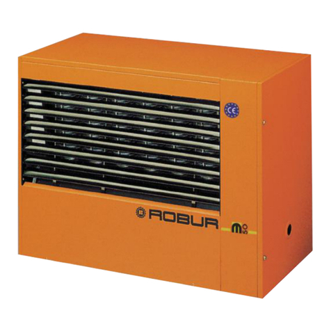
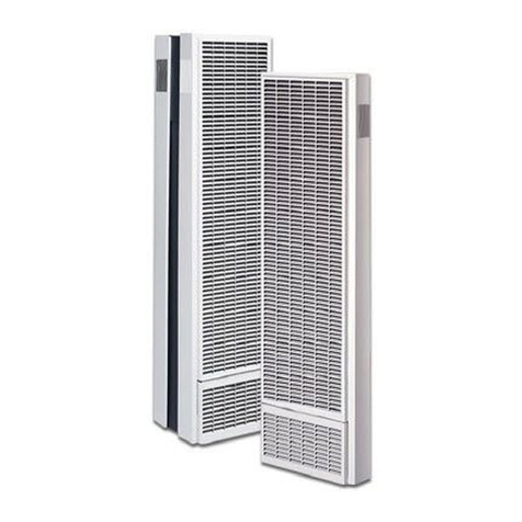
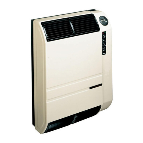
The warm air heaters in the Evoluzione range are independent heating appliances of the sealed circuit and
forced draught type.
They have been designed to be installed inside the room to be heated.
They may be set up to run on natural gas (G20) and L.P.G. (G30/G31) (the appliance belongs to category
II2H3B/P in accordance with the EN 1020 norm).
The combustion circuit is sealed off from the environment to be heated and complies with the requirements of
norm EN 1020 for type C appliances: intake of combustion air and outlet of exhaust gases occur outside and
are ensured by the operation of a blower which is located in the combustion circuit. The appliances are
approved also as type B appliances for installations where combustion air intake is permitted directly from the
room to be heated.
The operation of the heater is controlled by an ambient thermostat (not supplied as standard). When the
thermostat is activated, the electronic control unit, after a pre-wash time of about 30 seconds, ignites the
burner.
An electrode detects when ignition has occurred. If there is no flame, the electronic control unit halts operation
of the appliance.
A green ON light located on the right-hand side of the appliance indicates that ignition of the burner has
occurred (see item 5, Figure 2).
The combustion products pass through the heat exchangers internally. The heat exchangers receive the
current of air produced by the helicoidal fan, thus introducing warm air into the room.
The direction of the airflow can be adjusted up or down and/or from side to side by applying on the inlet grille
the (optional) adjustable fins (see “List of accessories” on page 27).
The helicoidal fan starts automatically only when it receives the command from the ventilation thermostat, that
is, only when the exchangers are warm, in order to prevent cold air from being introduced into the room.
Likewise, it stops when the exchangers are cold.
If the heat exchangers should overheat, because of abnormal operation, a limit thermostat is fitted which, if
required, cuts off power to the gas valve, which in turn cuts off the flow of fuel and makes the burner switch off.
Resetting the limit thermostat is an operation for professionally qualified personnel only, which restores
operation of the appliance after having identified the cause of overheating.
Upstream from the burner, a blower ensures the correct air-gas mixture and the forced expulsion to the
outside of the exhaust fumes deriving from combustion.
If the inlet or exhaust pipes are obstructed, or if the blower is operating inefficiently, the differential “air-gas
valve” control system interrupts the flow of combustion air to the burner.
The diagram in Figure 1 summarises winter operation of the heater.
The heating output and ventilation of the Evoluzione warm air heater are modulating: they can be reduced by
approximately 20% (see “TECHNICAL DATA” on page 5).
Operation on reduced power and ventilation allow ambient temperature to be kept constant, reducing gas
consumption and further lowering noise emissions into the environment.
Operation with automatic or manual modulation depends on the type of control units chosen (for further
information, see the paragraph “Other accessories” on page 29).
In the summer period, it is possible to operate the fan only, producing a pleasant movement of indoor air (for
further information see Section “For the User”, paragraph entitled “Summer”).
NOTE
