Features and technical data
Installation, use and maintenance manual – Next-G 7
1
1 FEATURES AND TECHNICAL DATA
1.1 FEATURES
1.1.1 Available range
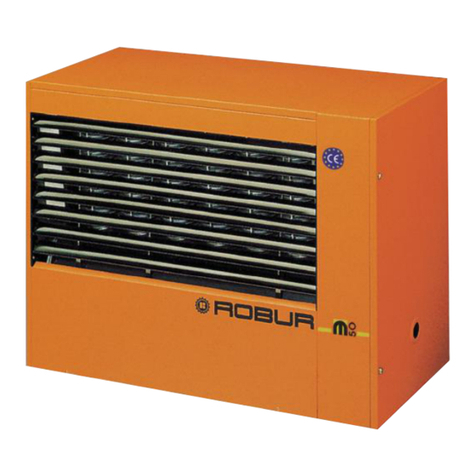
Next-G gas unit heaters are available in three versions:
▶
with horizontal ow, with xed speed axial fan (Next-G
series)
▶
with horizontal ow, with axial fan with brushless vari-
able speed motor (Next-G EC series)
▶
with horizontal ow, ductables, with centrifugal fan
(Next-G C series)
1.1.2 Operation
The Next-G series gas unit heater is an independent heat-
ing appliance with airtight combustion circuit and forced
air draft.
It has been designed to be installed inside the room to be
heated.
The combustion circuit is room sealed and meets the re-
quirements for type C appliances: combustion air supply
and ue gas exhaust discharge take place outdoors and
are ensured by the functioning of a blower inserted in the
combustion circuit.
The appliance is also approved for type B for installations
where it is allowed to take the combustion air directly
from the room to be heated.
The operation of the gas unit heater is controlled by a con-
trol device (not supplied).
The gas unit heater can operate at two heat output lev-
els or modulating heat output, at xed or modulating fan
speed.
The standard operation of the gas unit heater is in modu-
lation, thanks to the presence of the supplied room probe.
A blower upline of the burner mixes the air and gas and
expels the combustion fumes.
Products of gas combustion (natural gas or LPG) ow in-
ternally through the heat exchangers, which are invested
externally by the air current produced by the fan, deliver-
ing warm air ow into the room.
The fan starts automatically only when the heat exchang-
ers are hot, in order to prevent cold air from being intro-
duced into the room, and will turn o when the exchang-
ers are cold.
The air ow direction is adjustable vertically by means of
the revolving louvres of the grille.
If heat exchangers overheat due to malfunction, the tem-
perature probe cuts o the power supply to the gas valve
and drives the blower and the fan at maximum speed.
In the event of obstructions in the intake or exhaust duct,
or in the event of malfunction of the blower, the electron-
ic board will automatically modulate the gas unit heater
heat output.
In the event of obstructions or malfunction beyond the
permitted range, the gas valve stops and the gas unit
heater is switched o.
In summer it is possible to operate the fan only in order to
provide a pleasant air ow within the room.
1.1.3 Mechanical components
▶
Premix stainless steel burner.
▶
High head blower, with rotation speed modulation.
▶
Cylindrical stainless steel combustion chamber.
▶
Robur patented heat exchangers, made out of a spe-
cial aluminium die-cast alloy, with horizontal nning
on the air side and vertical nning on the ue gas ex-
haust side, with a very high heat exchange capacity.
▶
Corrugated stainless steel heat recovery exchangers
with very large exchange surface.
▶
External steel panelling with epoxy powder enamel
nish.
▶
Axial fan(s) with high air ow, with rotation speed var-
iation (for Next-G EC series).
▶
Axial fan(s) with high air ow, with xed speed (for
Next-G series).
▶
Centrifugal fan (for the Next-G C series).
1.1.4 Control and safety devices
▶
GEN10 control board with microprocessor, display and
selection keys, providing the following functions:
burner ignition
ame monitoring and modulation
blower management and blower speed control
fan speed control
heat exchanger temperature probe control
minimum ue gas temperature probe control
room temperature control with supplied probe
control of destratier function with optional probe
predictive start-up function control with optional
probe
Modbus communication
▶
Limit thermostat with manual reset against heat ex-
changers overheating.
▶
Gas solenoid valve.
