Rockinger RO RC-PC Series User manual

ROCKINGER Monitor-Set
zum Aufrüstsatz Drawbar Finder
ROCKINGER Monitor Set
for the upgrade kit Drawbar Finder
ROCKINGER set de Moniteur
par kit d’équipement
de Drawbar Finder
Montage- und Betriebsanleitung
Installation and operating instructions
Instructions de montage et d’utilisation
DE
EN
FR
Member of JOST World


Table of contents Monitor Set
ROCKINGER
Member of JOST World 15
EN
Note
EC Regulation ECE R 55-01 Annex 7 and the relevant regulations in
your country must be observed when installing the Drawbar Finder
Upgrade Kit. Always carry the installation and operating manual in the
vehicle.
Technical modifications reserved!
ROCKINGER Monitor Set
for Drawbar Finder Upgrade Kit
as optional equipment for upgrade kits and remote control for use with:
ROiRC-PC and
ROiRC-PL-2.0
for types ROi50, ROi50E and ROi50BNA.
Safety instructions 16
1. Installation 17 – 18
1.1 Before installation 17
1.2 Installation 17
1.3 System connections 18
2.
Operation
19 – 23
2.1 Operating sequence 19
2.2 Display menu / Main menu 20
2.3 Camera settings 21
2.4 Trigger settings 22
2.5 Autoscan settings 23
2.6 Advanced menu 23
3. Maintenance / 4. Problems 24
5. Disposal 25
Installation must be carried out by a specialist
workshop.
Read this manual carefully before installation.

ROCKINGER
Member of JOST World
4
16
EN
Safety instructions Monitor Set
WARNING: Do not open the housing – risk of electric
shock. Have all repair and maintenance work carried out
solely by qualified specialist personnel.
Please note: Any changes or modifications that are not explicitly appro-
ved in this manual may render your equipment’s warranty invalid and
cause it to malfunction. The monitor is not waterproof and is not suitable
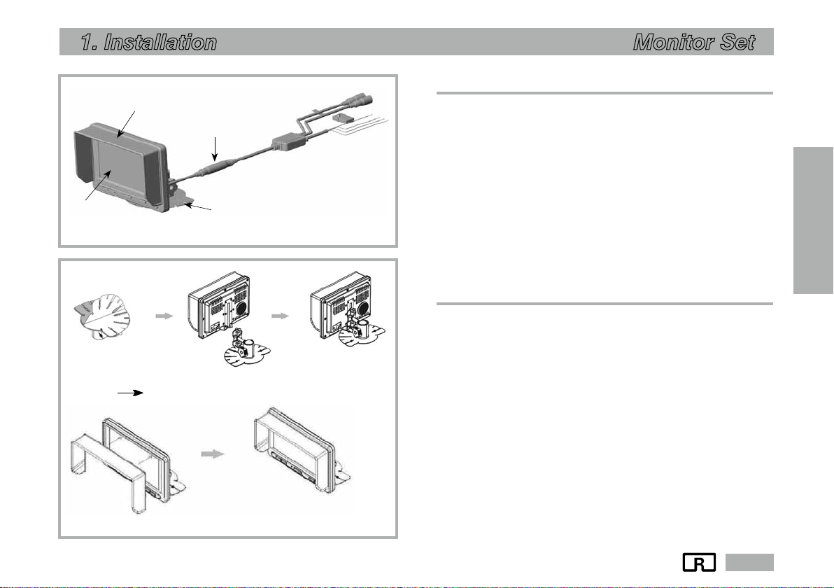
for use out of doors. Avoid kinks and abrasion when laying cables. Install
the monitor in a location in the driver’s cab where it does not obstruct the
driver’s field of vision. Make sure the monitor is securely fastened. Secu-
rely seal all holes made, to prevent damage to the vehicle.
Safety
x The system is only suitable for connection to a 12 V/24 V on-board
electrical system with negative vehicle ground.
x If dust or liquid has got inside the housing, please switch off the
device and seek advice from a qualified engineer before starting up
again.
Intended use
x Only in combination with ROiRC-PC and ROiRC-PL-2.0 for types
ROi50, ROi50 E and ROi50 BNA and associated Drawbar Finder
Upgrade Kits
– For installation in the driver's cab
– For connection to the 12 V /24 V on-board electrical system
General cleaning instructions
x Clean the device with a soft, slightly moistened cloth. Use a mild
household detergent. Never use strong solvents, such as thinners or
benzene, as these could damage the paint on the device.
Fig. 1 Safety instructions
CAUTION !
RISK OF
ELECTRIC SHOK
DO NOT OPEN !

ROCKINGER
Member of JOST World 17
EN
1. Installation Monitor Set
1.1 Before installation
When installing the monitor, please note:
x Have installation performed by an authorised specialist workshop
only
x Applicable regulations in your country
Note: Do not install the device in extremely hot or humid locations (radia-
tor, air duct, etc.) or in locations that are exposed to direct sunlight, exces-
sive dust, mechanical vibrations or impacts. If your vehicle has been par-
ked in direct sunlight for a longer period and the inside temperature has
risen considerably, you must allow the device to cool down before use.
1.2 Installation
x Fasten the holding fixture at a suitable position
x Slide the monitor into the rail
x Fit the sun visor to the edge of the monitor to prevent annoying
reflections
Fig. 2
Scope of delivery of ROCKINGER Drawbar Finder Monitor
Fig. 3 Installation
Holding fixture (rail installation)
Sun visor Monitor
Sun visor
Wiring harness
Monitor Holding fixture

ROCKINGER
Member of JOST World
4
18
EN
1. Installation Monitor Set
1.3 System connections
x Connect the extension cable (not shown) of the camera to the plug
(CA2)
x Connect the monitor plug to the wiring harness
x Connect to the power supply
x Cable colour black
Connect to terminal 31 (ground)
x Cable colour red with fuse
Connect to terminal 15 (+12 V/24 V with ignition ON)
Optional trigger connection
x Cable colour white, (CA2 TRI) reverse gear switching signal
x Cable colour green, (CA1 TRI) alternative second trigger
x Route and secure the wiring harness so that it cannot chafe or get
trapped.
Fig. 4 System connections
Camera
(not supplied)
CA1
CA2
Fuse
12/24V
GND
CA1 TRI
CA2 TRI
MONITOR

ROCKINGER
Member of JOST World 19
EN
2. Operation Monitor Set
2.1 Operating sequence
*Mains switch
1. Press the MAINS SWITCH to switch on the monitor.
2. Press the MAINS SWITCH to switch off the monitor.
œUP / DOWN
1. In menu mode, use the UP/DOWN button to go through the avai-
lable menu options.
åSELECT
1. Press the SELECT button to select CAMERA 1/CAMERA 2.
2. Also press SELECT to select options in the setup menu
¨MENU
1. Press the MENU button to view the display menu (short press) or
the main menu (long press).
2. Press once to open menu mode. Press again to exit menu mode.
3. If you do not press any more buttons for 7 seconds, the selection
menu disappears.
4. To return to the main menu from the submenu, press the Menu
button for more than 2 seconds.
ˆInput cable
–Mounting rail
ıLoudspeaker
Fig. 5 View of monitor

ROCKINGER
Member of JOST World
4
20
EN
ROE 70962
2. Operation Monitor Set
2.2 Display menu / Main menu
1. Display menu
x Briefly press the MENU button (min. 0.5 s) to view the display
menu.
x You can then view the image properties you wish to change using
the UP/DOWN buttons, and select them with SELECT.
x Select the brightness, contrast or colour saturation, then adjust
using UP/DOWN
Note: The display value for CAM1 and CAM2 is set separately.
2. Main Menu
x To view the MAIN MENU, press the MENU button a little longer
(more than 2 s).
x If you do not press any more buttons for 7 seconds, the OSD selec-
tion menu disappears.
Here you can select the following:
– Camera settings
– Trigger settings
– Setting the Auto Scan function
– Advanced menu
Note: If you connect a trigger line (see page 18), you will no longer be
able to open the main menu.
Fig. 6 Display menu
Fig. 7 Main menu

ROCKINGER
Member of JOST World 21
EN
2. Operation Monitor Set
2.3 Camera Settings
1. You can change the mirror image/normal image of the camera
(separate control of CAM 1/CAM 2).
2. You can change the UP/DOWN image of the camera (separate
control of CAM 1/CAM 2).
3. Each camera can be named, and the name of the selected camera
is shown on the OSD.
Fig. 8 Camera settings

ROCKINGER
Member of JOST World
4
22
EN
2. Operation Monitor Set
2.4 TRIGGER settings
Source: [CAM1; CAM2; SKIP]
xTwo triggers can be used, and each trigger source (CAM1; CAM2;
SKIP) can be selected.
xWhen the trigger is activated, the image of the selected source is
displayed.
Note: Trigger priority, if more than one is assigned: Trigger iTrigger 2
Delay: [0 Z 20 sec]
The delay of each trigger can be adjusted from 0 to 20 seconds.
Note: The delay settings can only be accessed with the SELECT button.
If a camera is activated by an intermittent signal (e.g. by a turn-
signal indicator), you must enable the delay to prevent the
image from flickering.
Marker: [ON; OFF]
You can set a marker (Fig. 10) if necessary. This function is not
required for using the Drawbar Finder.
Marker Settings: (Fig. 10)
Here, you can move the marker Left/Right and Up/Down, or expand it.
Note: If “MARKER” is set to “OFF”, the parking assistant marker is not
shown when the vehicle is shifted into reverse gear.
Fig. 9 Trigger setting
Fig. 10 Marker

ROCKINGER
Member of JOST World 23
EN
2. Operation Monitor Set
2.5 Auto Scan settings
(set the automatic scan function)
Auto Scan: [ON / OFF]
Cam 1 Delay: [0Z 20 sec]
Cam 2 Delay: [0Z 20 sec]
Note: The delay before a camera image is shown can be set between
0–20 seconds for each camera.
We recommend the setting “Auto Scan OFF” for using the
Drawbar Finder.
.
2.6 Advanced menu
Auto Power:
x“AUTO” setting: The monitor keeps the most recently saved settings.
The monitor starts up in either “On” mode or “Standby” mode,
depending on which mode was last enabled before the ignition
was switched off.
x“OFF” setting: The monitor remains in “Standby”, regardless of
which mode was last enabled before the ignition was switched off.
x“ON” setting: The monitor is switched on automatically when the
ignition is switched on, regardless of which mode was last enabled
before the ignition was switched off.
Factory Reset: Reset to the factory settings.
Fig. 11 Setting the Auto Scan function
Fig. 12 Advanced menu

ROCKINGER
Member of JOST World
4
24
EN
ROE 70962
3. Maintenance / 4. Problems Monitor Set
3. Maintenance
Clean the camera lens regularly to maintain the same
image quality. To do this, use mild cleaning agents and a
soft cloth to avoid scratching the lens. An unsatisfactory
image quality can also be caused by a dirty camera lens.
4. Problems
Problem
Monitor does not
function after ignition
ON
No camera image on
the monitor
Wrong camera image
on the monitor (shown
back-to-front)
Cause
3 A automotive blade-
type fuse defective
Connection cable not
connected correctly
Vehicle battery
too weak
Plug connections
loose or not connected
correctly
Trigger signal is set but
not available
Camera connectors
connected the wrong
way round
Incorrect signal input
selected on the monitor
Wrong menu setting
Remedy
Replace 3 A automotive
blade-type fuse
Check the voltage supply:
xred cable = terminal 15
(+12 V or +24V ignition
ON)
xblack cable = terminal 31
(ground)
Charge / replace
the battery
Check plug connections
and cables between the
camera and monitor
Apply trigger signal or deacti-
vate the trigger
Connect the camera
to CA 2
Select camera CA 2 with the
Select button
See chapter 2.3:
Camera settings

ROCKINGER
Member of JOST World 25
EN
5. Entsorgung Monitor Set
5. Disposal
Your product is made of high-quality materials and components that
can be recycled and reused.
If this product bears the symbol of a crossed-out wheelie bin shown
adjacent, this means that it is covered by European Directive 2002/96/
EC. Please find out about your local collection points for electrical and
electronic products and appliances.
Please pay attention to the local regulations, and do not dispose of
your old equipment with normal household waste. The correct disposal
of your old equipment will help to prevent possible negative conse-
quences for the environment and people’s health
Fig. 13 Disposal

JOST-Werke Deutschland GmbH · Siemensstr. 2, D-63263 Neu-Isenburg · Tel. +49(0) 61 02295-0 · Fax +49(0)61 02295 -298 · www.jost-world.com
MUB 016045 M 20 (REV --) 09/2020
This manual suits for next models
1
Table of contents