3
WARNING indicates a hazard, which,
if not avoided, could result in death or
serious injury.
CAUTION indicates a hazard, which,
if not avoided, might result in minor
or moderate injury.
CAUTION when used without the
alert symbol, indicates a situation that
could result in damage to the engine
or generator.
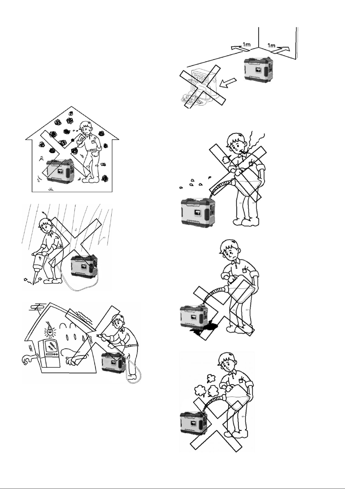
DANGER:
CARBON MONOXIDE
Using a generator indoors CAN KILL YOU
IN MINUTES.
Generator exhaust contains high levels
of carbon monoxide (CO), a poisonous
gas you cannot see or smell. If you can
smell the generator exhaust you are
breathing CO. But even if you cannot
smell the exhaust, you could be
breathing CO.
NEVER use a generator inside houses,
garages, crawlspaces, or other partly
enclosed areas. Deadly levels of carbon
monoxide can build up in these areas.
Using a fan or opening windows and
doors does NOT supply enough fresh air.
ONLY use a generator outdoors and far
away from open windows, doors, and
vents. These openings can pull in
generator exhaust.
Even if you use a generator correctly, CO
may leak into the house. ALWAYS use a
battery-powered or battery-backup CO
alarm in your house.
If you start to feel sick, dizzy, or weak
after the generator has been running,
move to fresh air RIGHT AWAY. See
a doctor. You could have carbon
monoxide poisoning."
WARNING:This generator
may emit highly flammable and
explosive gasoline vapors, which can
cause severe burns or even death if
ignited. A nearby open flame can lead to
explosion even if it isn’t directly in
contact with gasoline.
Do not operate near open flame.
Do not smoke near generator.
Always operate on a firm, level
surface.
Always turn generator off before
refueling. Allow generator to cool for at
least 2 minutes before removing fuel
cap. Loosen cap slowly to relieve
pressure in tank.
Do not overfill fuel tank. Gasoline
may expand during operation. Do not
fill to the top of the tank. Allow for
expansion.
Always check for spilled fuel before
operating.
Empty fuel tank before storing or
transporting the generator.
WARNING: This generator
produces powerful voltage, which can
result in electrocution.
ALWAYS ground the generator
before using it (see the “Ground the
Generator” portion of the “GENERATOR
PREPARATION” section).
Generator should only be plugged
into electrical devices, either directly or
with an extension cord. NEVER
connect to a building electrical system