3
2
WPROWADZENIE
Przeczytaj tę instrukcję przed wykonaniem ja-
kiejkolwiek operacji. Obowiązkowe jest prze-
czytanie tej instrukcji obsługi przed rozpoczę-
ciem jakiegokolwiek działania.
Prawidłowe działanie i pełna zgodność dzia-
łania tego produktu jest gwarantowana tylko
wtedy, gdy wszystkie instrukcje zawarte
w tej instrukcji są ściśle przestrzegane.
Gwarantujemy, że ten produkt jest zgodny ze
specyfikacjami technicznymi opisanymi
w niniejszej instrukcji. Producent nie ponosi
odpowiedzialności za jakiekolwiek niewłaści-
we zastosowania inne niż opisane w niniej-
szym dokumencie.
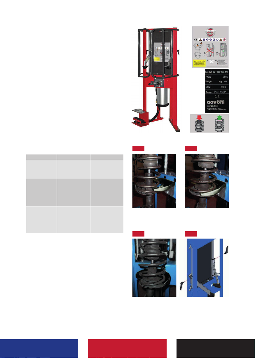
OPIS
Maszyna do montażu i demontażu amortyza-
torów, model GO 312, składa się z malowanej
metalowej ramy rurowej. Na tej konstrukcji za-
montowany jest pneumatyczny tłok zamoco-
wany przy ramie, jego przedłużenie
i ściskanie umożliwia ściskanie i uwalnianie
sprężyny utrzymywanej przez wsporniki ste-
rujące.
UŻYWANIE
Maszyna GO 312 to urządzenie do montażu
i demontażu amortyzatorów samochodów.
Każde inne użycie jest uważane za niewłaści-
we i nielogiczne. Producent nie ponosi odpo-
wiedzialności za ewentualne szkody spowo-
dowane nieprzestrzeganiem instrukcji.
INSTRUKCJE I OSTRZEŻENIA
Zastosowanie tego modelu maszyny GO 312
wymagało szczególnej uwagi. Ściśnięte sprę-
żyny mogą stanowić potencjalne zagrożenie
ze względu na siłę zebraną z powodu ściska-
nia. Maszyna ta musi być używana zawsze ze
specjalnym zabezpieczeniem przednim za-
montowanym prawidłowo na ramie.
Indywidualne środki ochrony
Tutaj wymienione są indywidualne środki
ochrony niezbędne do pracy z naszym pro-
duktem.
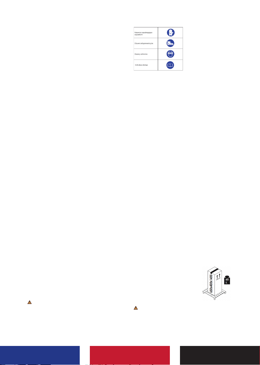
Piktogramy niebezpieczne
Maszyna jest wyposażona w piktogramy, które
pokazują pozostałe zagrożenia i indywidualne
środki ochronne, które należy stosować pod-
czas pracy.
Piktogramy są integralną częścią produktu.
W przypadku utraty, pogorszenia stanu lub
nieczytelności, wymagaj piktogramów od
konstruktora w celu ich natychmiastowego
zastąpienia. Zastąp piktogramy zawsze w tym
samym miejscu, w którym zostały usunięte
zgodnie z powyższym wzorem.
PRZEWÓZ - PRZEŁADUNEK
Maszyna waży kg. 65. Konieczne jest użycie
wózka do obsługi i przewozu.
Zamocuj paczkę na wózku przez paski, aby
ją zrównoważyć. Uchwyt z opieka w porządek
do unikać do rozstrój i do robić pakiet
o wymiarach 650x400x1400 mm spada, po-
wodując zagrożenie zarówno dla osoby odpo-
wiedzialnej za obsługę, jak i dla personelu w
pobliżu miejsca.
ROZPAKOWANIE
Maszyna jest pakowana w kartonowe pudełko
o wymiarach 650x400x1400 mm i zamykana
metalowymi klipsami.Na opakowaniu znajdują
się strzałki wskazujące, jak obchodzić się
z pudełkiem.Rozłóż opakowa-
nie w celu rozpakowania ma-
szyny. Ostrożnie wyjmij meta-
lowe klipsy na górze pudełka
i rozpakuj maszynę, wysuwając
ją z opakowania.
Wewnątrz pudełka znajdują się komponen-
ty i akcesoria maszyny. Zwróć uwagę,
i nie wyrzucaj ich z paczką.