Rockwood 31873 User manual

3/8"x13"PNEUMATIC
MINI BELT SANDER
INSTRUCTIONS
Item #31873

2Eastwood Technical Assistance: 800.343.9353 >> techelp@eastwood.com
The ROCKWOOD PNEUMATIC MINI BELT SANDER is compact and powerful with an adjustable angle
sanding arm for ease in grinding and sanding difficult to reach areas. It features a sealed ball bear-
ing drive assembly for smooth, low vibration operation and long life. The precision diecast housing
provides a solid foundation and offers ergonomic, one handed operation with a convenient handle
mounted paddle trigger.
CONTENTS
(1) Mini Belt Sander
(1) 4 mm Hex-Key Wrench
(3) 3/8” x 13” Abrasive Belts
(one installed)
(1) 1/4” NPT Air Inlet Coupling
SPECIFICATIONS
RPM: 18,000 free speed
Air Consumption: 4 CFM [113 L/m] @90 PSI [6.2 bar]
Inlet thread size: 1/4” FNPT
Required Belt Size: 3/8” x 13”, minimum 18,000 RPM
REQUIRED FOR USE
• The inlet air supply should have a moisture separator capable of removing all moisture and
impurities from the air supply. Moisture in the air supply will cause poor tool performance
and damage.
• A suitable regulator must be used to limit incoming air pressure to 90 PSI maximum. Excessive
air pressure can cause permanent damage to the unit and possible serious personal injury from
bursting.
• For best results, a compressor capable of providing a minimum of 4 CFM @ 90 PSI is recom-
mended for best performance. Less available CFM will negatively affect the performance of the
Belt Sander and may overwork the compressor.

To order parts and supplies: 800.343.9353 >> eastwood.com 3
READ INSTRUCTIONS
• Thoroughly read and understand these product instructions before using
this tool. Failure to follow all warnings can result in tool damage or serious
physical injury.
• Keep these product instructions for future reference.
RESPIRATORY HAZARD!
• Dust and fine particulate matter is generated during the sanding process
which can contain toxic substances such as lead, silica, solvents and oth-
ers. Breathing this dust and fine particulate matter can cause many serious
respiratory health conditions. Always use NIOSH approved respiratory
protection while using this Sander.
EYE INJURY HAZARD!
• Rapidly moving abrasive surfaces can eject metal particles, dirt and debris
at high velocity. Always wear ANSI approved eye protection when operating
this tool.
HEARING DAMAGE HAZARD!
• This tool emits high sound levels while operating. Use ANSI approved ear
protection when operating.
DANGER indicates a hazardous situation which, if not avoided, will result in death or serious injury.
WARNING indicates a hazardous situation which, if not avoided, could result in death or serious injury.
CAUTION used with the safety alert symbol, indicates a hazardous situation which, if not avoided,
could result in minor or moderate injury.
NOTICE is used to address practices not related to personal injury.
SAFETY INFORMATION
The following explanations are displayed in this manual, on the labeling, and on all other information
provided with this product:

4Eastwood Technical Assistance: 800.343.9353 >> techelp@eastwood.com
BURSTING HAZARD!
• Do not exceed 90 psi (6.2 bar) of tool inlet pressure. Permanent tool
damage and/or bursting could occur and cause personal injury.
INJURY HAZARD!
• This tool has high-speed, abrasive surfaces which can quickly cause injury.
Keep fingers and hands away from moving parts when operating. Wear
thick, well-fitting work gloves and keep loose clothing, sleeves, cords,
jewelry and hair away from moving parts.
• This tool can eject sparks which can ignite flammable materials. Do not
operate near flammable materials and keep all persons and pets away
from the work area.
• Always make sure the workpiece is securely clamped or anchored to avoid
sudden movements which could result in injury.
• Always disconnect tool from air supply when changing Abrasive Belts
or making adjustments to prevent accidental tool starting and potential
severe injury.
• Frequently inspect Abrasive Belt and tool condition. If cracks develop,
discontinue tool use immediately and replace damaged pad. ONLY USE
replacement Abrasive Belts rated for 18,000 RPM or greater otherwise
severe injury can result in the event of Belt failure.
VIBRATION INJURY HAZARD!
• This tool will vibrate during use! Repeated exposure to vibration may cause
physical injury.
SET UP & CONNECTION
• Wrap white thread sealing tape (not included) around the threads of the included
1/4” Male NPT quick disconnect fitting then thread it into the 1/4” NPT inlet threads
of the Belt Sander Body.
• Attach Air Supply to Inlet Fitting.
Be sure that the air supply to the tool is clean and dry. Moisture in the supply
line will quickly damage the air motor and valves.
A minimum 3/8” I.D. air line should be used for optimal performance.

To order parts and supplies: 800.343.9353 >> eastwood.com 5
OPERATION
• Depress Throttle Paddle inward with fingers to operate tool.
• Keep the broad work surface of the Abrasive Belt parallel to the work surface whenever
possible to minimize uneven wear and maximize usable life.
• Always maintain a firm grip while operating tool, do not force but allow the rotational speed
of the Abrasive Belt to do the work.
• Be sure that the workpiece is clamped down or held securely to minimize the danger of injury
while operating tool.
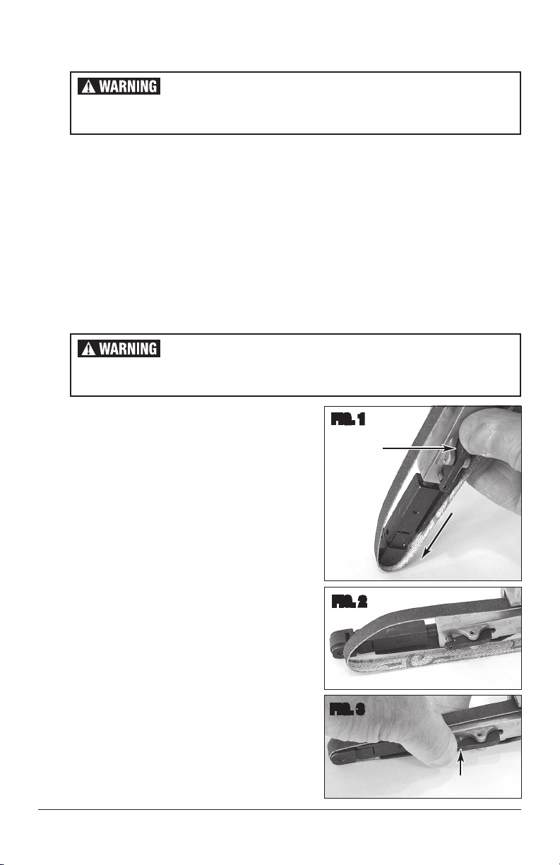
ABRASIVE BELT REPLACEMENT
The Abrasive Belts are quickly and easily changed. No
tools are required.
The following steps describe how to do this:
• The end of the Abrasive Belt Arm is spring loaded
to keep the proper tension on the Abrasive Belts.
While holding the tool firmly, push inward on the
end of the Abrasive Belt Arm while depressing
the Thumb-Lever Latch (FIG 1). NOTE: The Guide
Pin will move inward until it locates under the
Latch portion of the Thumb-Lever Latch holding
it in the retracted position while the Abrasive Belt
is changed (FIG 2).
• Pull the worn Abrasive Belt free of the Drive
Drum and discard.
• Slide the replacement Abrasive Belt over the
Drive Drum and Idle Roller at the end of the Abra-
sive Belt Arm (FIG 2). NOTE: Be sure the Abra-
sive Belt is slid fully over the Guide Bar located on
the upper surface of the Abrasive Belt Arm.
• Depress the Thumb-Lever Latch to release the
Guide Pin restoring full spring pressure (FIG 3).
INJURY HAZARD!
Disconnect air supply from the tool to prevent accidental starting and
potential injury while installing or removing Abrasive Belts.
FIG. 1
INJURY HAZARD!
Disconnect air supply from the tool to prevent accidental starting and
potential injury while installing or removing Abrasive Belts.
Push In
to Latch
Push Down
to Compress
✓
✓
Push In to Unlatch
✓
FIG. 2
FIG. 3

6Eastwood Technical Assistance: 800.343.9353 >> techelp@eastwood.com
ADJUSTING SANDING ARM ANGLE
• Disconnect air supply from the tool to prevent
accidental starting and potential injury while
adjusting the Abrasive Belt Arm Angle.
• Using the included 4mm Hex Key, loosen the
Angle Adjusting Screw located on the upper side
of the Abrasive Arm Assembly (FIG 4), rotate
Arm to desired position then tighten screw
securely.
ADJUSTING BELT TRACKING
• Disconnect air supply from the tool to prevent
accidental starting and potential injury while
adjusting the Abrasive Belt Tracking. The Track-
ing Adjustment Screw is located at the outer right
side of the Abrasive Arm Assembly (FIG 5).
• Using a Phillips screwdriver, turning the screw
clockwise (as viewed from the right side) will
cause the belt to track left while turning the
screw counter-clockwise will cause the belt to
track right.
MAINTENANCE
• Before each use, add a few drops of a quality air tool oil (not included).
• If tool is to be unused for an extended period, add 10 drops of air tool oil directly to the air inlet
then store the tool, inlet up.
• With the air supply disconnected, periodically check that the belt is not worn, torn and is tight.
FIG. 4
Rotate Arm
FIG. 5
INJURY HAZARD!
Disconnect air supply from the tool to prevent accidental starting and
potential injury while installing or removing Abrasive Belts.
INJURY HAZARD!
Disconnect air supply from the tool to prevent accidental starting and
potential injury while adjusting Belt Tracking.

To order parts and supplies: 800.343.9353 >> eastwood.com 7
PROBLEM CAUSE CORRECTION
Tool Doesn’t
Respond to
Paddle
Depression
Insufficient CFM
at tool inlet
(4 CFM @ 90
PSI minimum
for best results)
Verify sufficient air supply to tool.
Tool contaminat-
ed by moisture Check for moisture in air line and tool air inlet.
Tool Perfor-
mance is Slow
or Sluggish
Insufficient CFM
at tool inlet
(4 CFM @ 90
PSI minimum
for best results)
Verify sufficient air supply to tool
Tool contaminat-
ed by moisture Check for moisture in air line and tool air inlet.
Tool Vibrates
Excessively
During Use
Torn or
loose belt
Stop use immediately and check for torn belt.
Check for loose belt.
Tool Emits
Excessive or
Unusual Noise
During Use
Lack of lubrica-
tion in air motor Stop use immediately and add a quality air tool oil.
TROUBLESHOOTING

ADDITIONAL ITEMS
#30661 5 Pack of 60 Grit, 3/8” x 13” Abrasive Belts
#30662 5 Pack of 80 Grit, 3/8” x 13” Abrasive Belts
#70491 Eastwood Industrial Air Hose, 3/8” x 25’
#70492 Eastwood Industrial Air Hose, 3/8” x 50’
© Copyright 2018 Easthill Group, Inc. 5/18 Instruction item #31873Q Rev 2
If you have any questions about the use of this product, please contact
The Eastwood Technical Assistance Service Department: 800.343.9353 >> email: techelp@eastwood.com
PDF version of this manual is available at eastwood.com
The Eastwood Company 263 Shoemaker Road, Pottstown, PA 19464, USA
800.343.9353 eastwood.com
Table of contents
Other Rockwood Sander manuals
Popular Sander manuals by other brands

Parkside
Parkside PPS 200 C2 Translation of the original instructions

Ingersoll-Rand
Ingersoll-Rand 317 instructions

Bosch
Bosch Professional GTR 550 Original instructions

Gesswein
Gesswein ULTRAMAX UM-1200 instruction manual

Parkside
Parkside PBS 600 B1 Translation of the original instructions

Rockwell
Rockwell RD4161 manual