Roddenberry PRP1769 User manual

#PRP1769
Star Trek: First Contact
Phaser Rifle
Prop Kit Assembly Manual
Thank you for your purchase of the Roddenberry.com Star Trek: First Contact Phaser Rie Prop Kit,
also as used in Star Trek: Insurrection and as the base for the modied rie from Star Trek: Nemesis.
This is the rst time a kit of the First Contact “round-nose” rie produced using the original master tooling has been
made available, and will produce a static non-electronic prop that’s light in weight due to casting the rie hollow.
Neither electronics nor a carry strap are included. Details for purchasing and installing
simple electronics with modication of the phaser rie are at Pagse 6 of the instructions.
Modications to make a Nemesis rie are not covered in this kit or instruction book.
Optional instructions not strictly necessary for the completion of the basic rie prop are in blue italics.

#PRP1769 - STAR TREK: Fi R S T Co n T A C T Ph A S E R Ri F l E PR o P Ki T AS S E m b l y mA n u A l
2
Optional Parts (not included):
Carry strap (may use plain black 2” seat belt
webbing screwed onto the rie or a retractable
seat belt assembly -- the original used was the
“Superior” #46-2050B replacement seat belt,
modied to t in the rie stock -- other retractable
belts or mechanisms may also work as the original
belt mechanism may no longer be available)
1 @ 1 3/4” and 1 @ 1/4” “Chicago” two-piece post
screws (available at hardware and leather supply
stores)
Washer(s) for carry strap loop
Silver metal tape for scope parts
Optional Tools:
Dremel moto tool with assorted bits
3/64” or a #56 drill bit
Taps in 4-40 and 0-90 threads
Other Paints needed:
Semi-gloss or gloss black hobby jar paint
Hobby jar (Buff) or spray can light beige or off-white
(Krylon Almond or Ivory or similar)
BASIC INVENTORY:
Parts List:
Hollow-cast “round-nose” phaser rie casting
Buttstock carry strap cover
Scope with scope bottom cover
2 force-setting buttons
Clear target sight block
Orange scope detail
Scope ashlight reector (resin casting)
Metal front carry strap loop
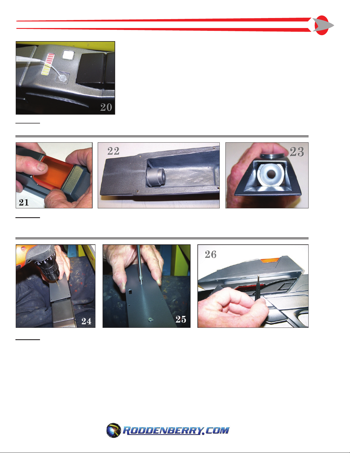
Power display and target sight graphics
Red transparent plate for left side
Additional left side plate for
optional electronics installation
Hardware included:
6 @ 2-56 x 3/16” screws
4 @ 4-40 x 1/2”
3 @ 0-90 x 1/8”
2 @ 5/8” wood screws
Tools and Supplies needed:
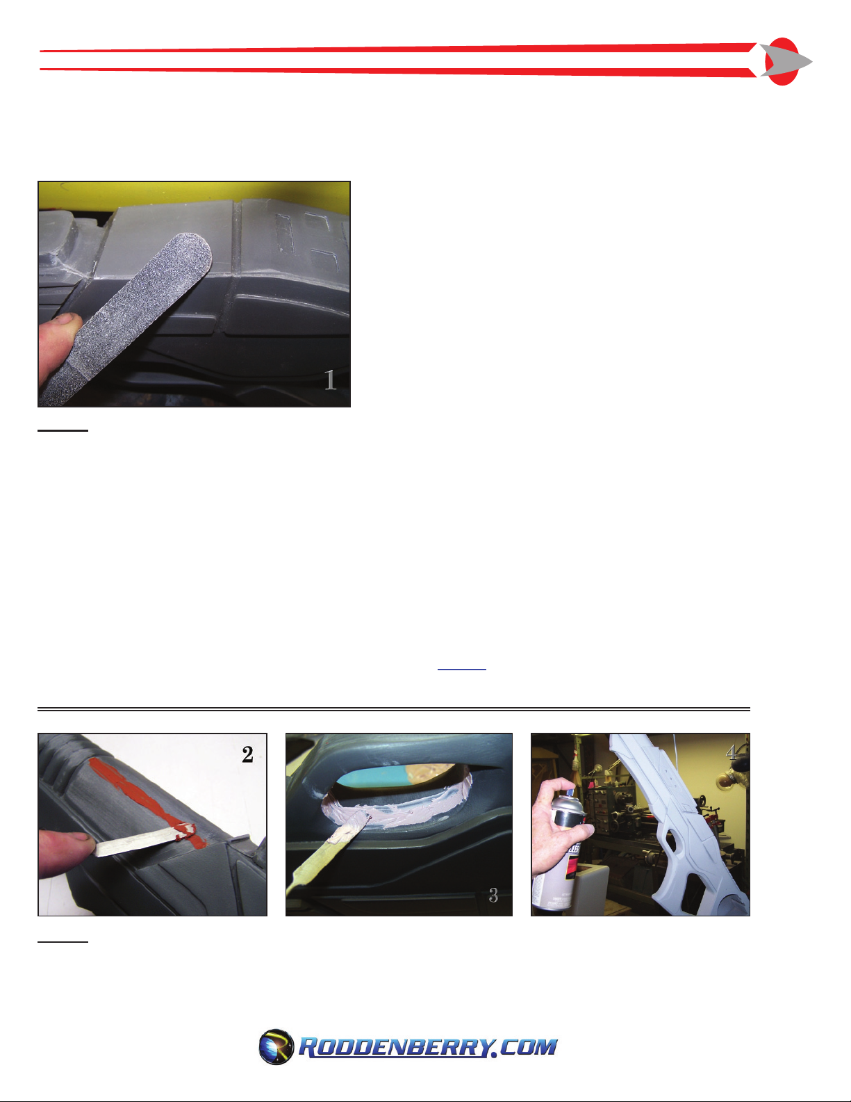
Sandpaper (220-320 rough grit, 400-600 nish grit)
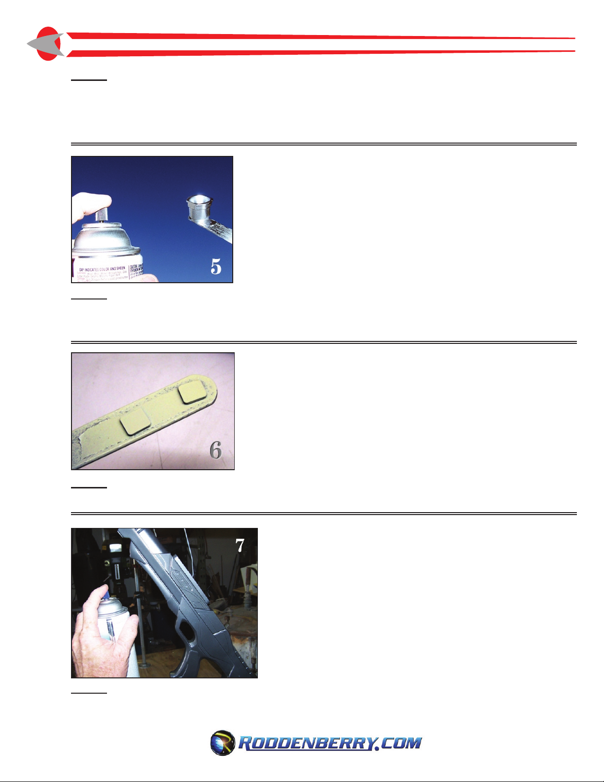
Auto body spot
Putty
Bondo plastic ller or similar
Cyanoacrylate (CA) glue with glue accelerator
5-minute epoxy
Drill with 3/32” bit
Countersink bit
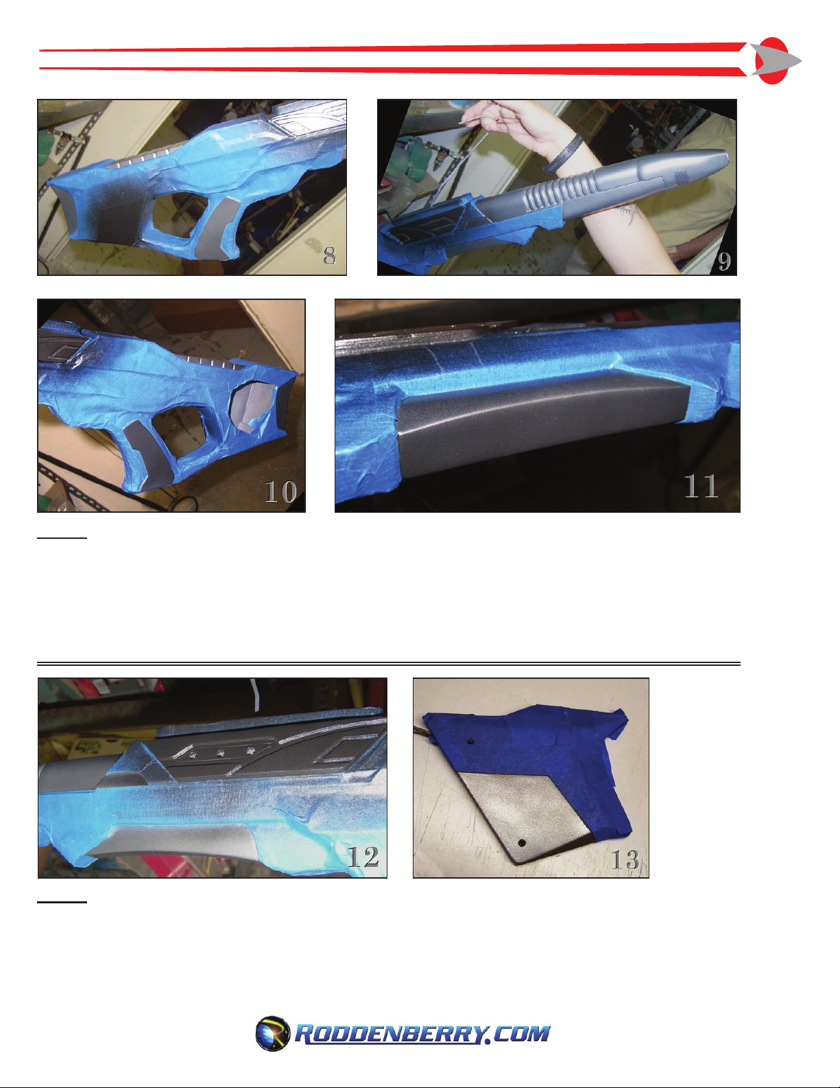
Masking tape (blue painter’s tape recommended)
Small hobby paint brush
Small Philips screwdriver
Spray Paints needed:
Primer (sandable-type recommended)
Plastikote 7173 or medium metallic gray equivalent
Plastikote 7179 or darker gunmetal metallic gray
equivalent
Semi-at black
Metallic silver or chrome aluminum
IMPORTANT NOTE:
The general rule of thumb whenever you are gluing anything to painted parts is to scrape away
any paint in your gluing joint (without it becoming visible beyond the glued part!), as parts glued to
paint won’t stick as well -- resin-to-resin is the strongest.

#PRP1769 - STAR TREK: Fi R S T Co n T A C T Ph A S E R Ri F l E PR o P Ki T AS S E m b l y mA n u A l 3
Step 1:
Start by sanding all mold lines and other spots from the edges of the castings [Fig. 1]. Test t the scope,
and the two other scope parts, make sure they work well. Also try the t of the carry strap cover.
A carrying strap is not necessary for the ultimate nished look of your phaser rie prop, and one is
not included in this kit.
If you plan to install a carrying strap, note that because of the hollow-cast construction, any screws you put
in might be going into a thin wall, and will be a weak point if your strap is anything other than a decorative
detail. Regardless if you’re installing a regular length or a retracted dummy strap -- or a functioning
retractable one, you will want to make all the preparations for its addition before you paint the rie, and
that also goes for any modications you wish to make to the sight or rie for electronics.
Details for installing both strap and electronics begin at Page 9 of the instructions. If you plan to
install either a strap or electronics, skip to Page 9 and then come back to Step 2 for painting.
Step 2;
Prepare the resin parts by sanding the surfaces to roughen them up slightly, ll in any objectionable spots
or bubbles with spot putty or bondo [Fig. 2 and 3], then sand smooth and spray all of the rie with primer --
repeat if you nd any aws you missed previously [Fig. 4].
Wash all your resin castings using soap and water to clean off any traces of mold release which
might interfere with the eventual paint nish.
PREPARATION ANd ASSEMBlY:

#PRP1769 - STAR TREK: Fi R S T Co n T A C T Ph A S E R Ri F l E PR o P Ki T AS S E m b l y mA n u A l
4
Step 3;
Drill the four 3/32” holes in the left side rie stock for securing the carry strap cover -- there are 4 divots
for location. A tap is not necessary for screwing the 4-40 x 1/2” screws, but it may come in handy. Drill the
countersinks in each of the holes in the carry strap cover, test the screws so they appear as at as possible,
and don’t go too deep!
Step 4;
Primer, then spray in metallic silver or chrome aluminum the scope ashlight reector, then set aside
[Fig. 5]. Also primer and paint in black the carry strap loop.
Step 5;
Primer and paint in light beige/off-white the two forcesetting buttons [Fig. 6].
Step 6;
When ready, paint the entire main rie body, scope, and carry strap cover in Plastikote 7173/medium
metallic gray or its available equivalent [Fig. 7].

#PRP1769 - STAR TREK: Fi R S T Co n T A C T Ph A S E R Ri F l E PR o P Ki T AS S E m b l y mA n u A l 5
Step 7;
When dry enough to where you’re sure masking tape won’t lift paint off (you may be waiting a few hours or
even until the next day in between painting the different colors -- taking your time with this step makes all
the difference in the world in achieving a professional-looking prop), mask where shown in Figs. 8 to 13 to
expose all of the contrasting color panels. Spray in semi-at black the handgrip panels, the “foregrip” area
underneath in front of the trigger guard, the large squared detail on top of the body, the rear shoulder stock
region, and the front barrel.
Step 8;
When the black paint is dry, mask over the black areas, leaving the other areas exposed (the lower front
of the carry strap cover and its opposite side on the right, the two middle trapezoidal areas, and the small
trapezoid regions left and right in between the larger side detail and the black barrel as shown in Figs. 12
and 13). Then spray in Plastikote 7179/darker gunmetal metallic gray. Remove all masking when dry and
set aside to let the paint cure out.

#PRP1769 - STAR TREK: Fi R S T Co n T A C T Ph A S E R Ri F l E PR o P Ki T AS S E m b l y mA n u A l
6
Step 9;
Paint with a brush the sunk-in detailing on the two large inverted trapezoids on both sides of the rie
[Fig. 14]. Apply epoxy to the red plastic cover to the left side, covering the three holes [Fig. 15],
(or LEDs if you are lighting up this detail).
Step 10;
Scrape the paint from the back of the scope where the target block is glued to. Note that the block will t
into its space only one way due to its angles. Epoxy or CA glue the block to the sight [Figs. 16 and 17].
Note: if you’re not making the scope light up with electronics, you may use a piece of silver metal tape or
white paper or plastic on the inside surfaces of both the clear block and orange top to make them appear to
light from within.
Step 11;
Cut out the vinyl target sticker with an X-acto knife and a ruler, or a pair of scissors, and apply to the clear
block. It is recommended you use a mild solution of soap and water and a Q-tip for application, this allows
you to position the sticker exactly and also to eliminate air bubbles behind the sticker [Figs. 18 and 19].
Avoid getting water on the outside of the sticker if you can -- while there is a protective matte nish on the
sticker, it is possible it could get damaged.

#PRP1769 - STAR TREK: Fi R S T Co n T A C T Ph A S E R Ri F l E PR o P Ki T AS S E m b l y mA n u A l 7
Step 12;
Apply the paper bargraph graphic, and glue on the two force setting buttons [Fig. 20].
Step 13:
Glue the orange scope detail to the top of the scope using epoxy or CA [Fig. 21]. Also glue the ashlight
reector to the front of the scope [Figs. 22 and 23].
Step 14:
Place the scope’s bottom plate on the rie. Be sure it’s straight to the main body and with the back edge
of the plate directly over the angular corner at the top of the body behind the raised scope mount oval
[see Fig. 26 and elsewhere], with the slotted hole to the left side and the smaller end to the front. Hold in
place and drill two screw holes (or one at a time) [Fig. 24], then screw the plate in place with the two wood
screws [Fig. 25]. Screw the scope onto the plate using 6 @ 2-56 x 3/16” at head screws [Fig. 26].
Glue may be used for added strength along with the screws for the scope, but it will make it very difcult to
take the scope apart without damage if you want to install electronics later.
Screw the carry strap cover on the stock using the 4 @ 4-40 x 1/2” screws.

#PRP1769 - STAR TREK: Fi R S T Co n T A C T Ph A S E R Ri F l E PR o P Ki T AS S E m b l y mA n u A l
8
The basic First Contact Phaser Rie is nished!
I
MPORTANT NOTES:
The physical reproduction by any means known or yet to be invented (including molding
and recasting, reverse-engineering, and stereo lithography scanning and printing) of this
Roddenberry.com Star Trek: First Contact Phaser Rie Prop Kit or its parts and graphics,
or reproducing any pre-existing parts and graphics, is expressly prohibited under U.S. and
international copyright and product protection laws.
Copyright © 2009 Roddenberry Productions.
Star Trek and related marks and logos are Trademarks of CBS Studios Inc. All rights reserved.

#PRP1769 - STAR TREK: Fi R S T Co n T A C T Ph A S E R Ri F l E PR o P Ki T AS S E m b l y mA n u A l 9
Step 1:
Probably the best way to secure the front end of the optional strap on this rie (either retracting or dummy)
is to use a two-piece post screw (aka Chicago screw) that’s 1/3/4” in length, which will be enough to go
through the rie and allow the carry strap loop to hang on the exposed post with swivel action. Drill a hole
the diameter of your post through both left and right sides of the rie where the strap will go, or cut in a
much bigger hole with your dremel tool and ll in the local cavity with bondo. Then sand smooth and drill
your post hole -- which will make that entire area stronger. You will end up with an exposed post head or
screw on the right side which can be left as is or painted to match, and both post and strap loop can be
added later after painting [Fig. 33].
Step 2:
Insert one end of the strap in the carry strap cover (inside-to-out) and screw to the inside of the buttstock
cavity, or install your retracting mechanism, then screw the cover onto the rie [Fig. 34]. If it is a retractable,
be sure you don’t lose the loose end into the mechanism. Loop the other end of the strap around the strap loop
and secure with a 1/4” max. length Chicago screw as was originally done, or you can use glue such as Barge
contact cement or by sewing or pop-riveting it...preferably before you screw the strap loop on, as it can be
difcult enough to work with the strap while on the painted rie, let alone with an already attached front end.
The following options are for more experienced prop and model makers, which should be completed
before painting...
OPTIONAl STRAP INSTAllATION (before painting]:

#PRP1769 - STAR TREK: Fi R S T Co n T A C T Ph A S E R Ri F l E PR o P Ki T AS S E m b l y mA n u A l
10
The following assumes you have a minimum rudimentary knowledge of wiring electronic circuits
to connect up LED lights with a switch and a battery power supply...
OPTIONAl ElECTRONICS INSTAllATION (before painting]:
If desired, you can also light up the red plate on the left side of the rie, using 3 red LEDs wired to the
scope circuit -- use a wire hook to pull wires out from inside the rie. The 3 LEDs should have the bottom
ange step sanded off to make it easier to install.
You may also put in an emitter LED and a trigger; for this one, be sure you use enough wire, and pull
through using at least a 2 foot length of 1/8” metal rod -- it’s possible you won’t be able to get a wire
through because of unavoidable blockage from casting or the strap installation.
Electronics for the rie originally was done for the scope and the force indicator bargraph; there was no light
for the emitter nor was there a trigger. The ashlight reector for the scope can have one or more white
LEDs added to make it shine out like the original ashlight, or you can substitute a real ashlight head if
desired. Glue on translucent diffusion sheets or plates over the existing voids and light these from within
with LEDs. These can all be activated with a slide switch which is show accurate -- there’s a place in the
laser cut plate for the switch; you will have to make room in the scope body for whatever size slide switch
you choose to use.

#PRP1769 - STAR TREK: Fi R S T Co n T A C T Ph A S E R Ri F l E PR o P Ki T AS S E m b l y mA n u A l 11
A push button trigger may be installed (originally it was a at “tactile” switch): dremel in a hole where the
trigger goes and glue a wired trigger in place.
(Note that on original ries, actual trigger switches were found on the “square-nose” rie used only in
First Contact, and this only turned on the scope lights -- there were no emitter lights nor were there any
trigger switches on the round-nose or the twin-handled “exo” ries. The switch used is pictured above.)
The bargraph (available at online stores or certain electronic supply or surplus stores) has its own power
source with a separate switch; and all that’s needed for a light-up display is a 5-count circuit board like
those used for t-shirts and so forth, a 3V power supply, and a slide switch. The bargraph should be wired
so it counts from the center-out, or set for “random” ashing using your circuit board -- this simulates the
“rotating phaser frequencies” to keep the Borg drone defenses guessing. Sources for the circuit board
include: the original which was available at Michael’s as the “Darcy” brand tshirt LED counter, any cheap
electronic toy “ray gun” or similar that has a ashing 5-sequencing light circuit, etc.
The bargraph on original ries is a 10-element LED block with 5 LEDs each of red and green -- Radio
Shack sold this one in the past, but it may no longer be available there. Any of the other color bargraphs
may be substituted if you can’t nd the half red-half green version. Mark where the bargraph should go
on the rie with a pencil, and dremel out the space until you can t the bargraph in place --pre-wire the
bargraph before nal installation!
Included in the kit is a plate to replace the one on the left side below the bargraph, this may be secured with
the included 3 @ 0-90 screws, so you’ll need to cut a hole in the left side smaller than the laser cut plate,
completely removing the remaining raised detail. Drill the 3 mounting holes with a 3/64” bit, or a #56 bit.
You should secure the battery pack so it’s not hanging loose in the rie (there’s enough room for a 2-cell
AAA pack or smaller), you may want to add plastic to make a interior box and/or use soft foam stuffed in
there. The slide switch is then secured to the plate, which is then screwed to the rie. The screws should
thread into the resin so threading the holes with a tap is unnecessary.
The two force-setting buttons are not functional on original ries, but of course you can make them work if
you want.
Table of contents
Popular Toy manuals by other brands

Trix
Trix Minitrix BR 110 manual

FLIGHT DESIGN
FLIGHT DESIGN CT2K Parts and assembly manual

REVELL
REVELL Salzgitter AMG Mercedes C-Klasse DTM 2009 "Gary... Assembly instructions

MTHTrains
MTHTrains RailKing NYC 4-6-4 operating instructions

ENGINO
ENGINO Eiffel Tower Assembly instructions

TP Toys
TP Toys Splash and Play Happy Chef Wooden Mud... Instructions for assembly, maintenance and safe use