Factory Default Settings:
Access Mode User codes or user cards
Format All Bits
Card Storage (MAX 1000 cards) None
Master Code 1234 (4 digits)
Relay Strike Time 1 second
Key Press Interval Time 5 seconds (fixed)
User Code Input Waiting Time 5 seconds
Programming Mode Delay Time 30 seconds (fixed)
First Time Keypad Use
Take these steps the first time the keypad is programmed.
Programming Instructions
1. Codes are programmed to have 4~6 digits in length. All codes must be the same
length.
2. To enter Programming Mode, enter the Master Code twice. The keypad will sound
1 beep and the LED will turn yellow.
Enter: (Default Master Code is 1234).
12341234
3. To exit Programming Mode, press # .The keypad will sound 1 beep and the LED will
turn blue.
4. Take note of the keypad status LED:
- Solid Blue: Standby Mode
- Solid Yellow: Programming Mode
- Flashing Green: Awaiting code /card entry
E. Setting Access Mode
1. Enter Programming Mode by entering the Master Code twice. The LED will turn yellow.
0
00
2. Enter . The LED will flash yellow.
3. Enter one of the following:
User card Only
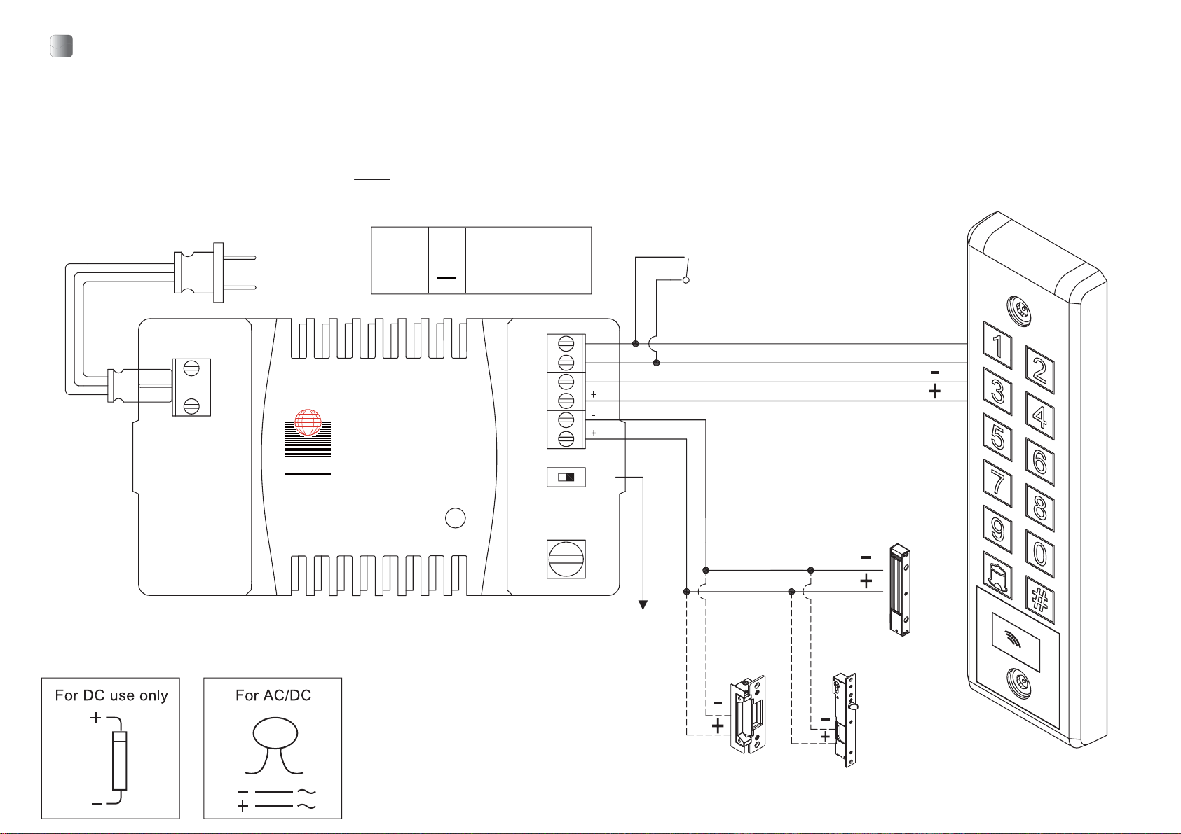
Notes:
1. It is suggested to use #22-26 AWG insulation wire.
2. With CE qualified EMC specification.
3. The door strike or electronic switch must have a varistor or a diode across the
door strike terminals to suppress the back EMF of the strike-failure to do so will
damage the contacts and electronic components, or even burn the controller.
4. There are several ways the ROFU 9860 proximity keypad reader may be powered:
● Using the supplied ROFU 9126T 12VDC Plug In Switching Power Supply
● Using a 12VDC or a 24VDC switching or linear power supply
(Note: ROFU 9126T Plug In Power Supply is designed to connect keypads,
electrified locks, exit buttons and switches. Higher efficiency, smaller size and weight
are perfectly for the 9860 keypad reader)
Code Length New Master Code
4 digits
5 digits
6 digits
1234
12345
123456
D. Programming the Master Card
B. Programming Code Length
Warning: After a new code length is programmed, all user codes and cards will be
deleted and the Master Code will be reset.
2. Enter . The LED will flash yellow.
3. Enter . The keypad will sound 1 beep and the LED will flash yellow.
4. Enter the desired code length. This must be a number from 4~6. The keypad will
sound 7 beeps and the LED will turn yellow.
5. Exit Programming Mode by pressing .
Note:The Master Code will reset depending on the programmed code length.These
will be the new Master Codes after the code length is reset:
9
0 4
#
C. Programming the Master Code
1. Enter Programming Mode by entering the Master Code twice . The LED will turn yellow.
(Default Master Code is 1234).
2. Enter . The LED will flash yellow.
3. Enter the new Master Code twice. The keypad will sound 1 beep and the LED will
turn yellow.
4. Exit Programming Mode by pressing .
Example: If the desired new Master Code is 4567, enter: .
4 5 6 7 4 5 6 7
3
#
A. Enter Programming Mode
Enter: 1 2 3 4 1 2 3 4 (Default Master Code is 1234).
In addition to a Master Code, a Master Card can also be programmed. Swiping a
Master Card will give direct access to Programming Mode.
1. Enter Programming Mode by entering the Master Code twice. The LED will turn yellow.
(Default Master Code is 1234)
2. Enter . The LED will flash green.
7
3. If the LED is solid green, a Master Card is already programmed. Clear it by entering
. The keypad will sound 1 beep and the LED will start flashing green.
4. Swipe a proximity card. The keypad will sound 1 beep and the LED will turn yellow.
This card is now the Master Card.
5. Exit Programming Mode by pressing .
#
1. Enter Programming Mode by entering the Master Code twice . The LED will turn yellow.
(Default Master Code is 1234).
Note: The Master Code must not be the same as a user code.