CADDX NXG-183x-EUR Series User manual

© 2021 Carrier 1 / 12 P/N 466-5559-EN • REV E • ISS 15OCT21
NXG-183x-EUR Series Keypad User Manual
1
Description
The NXG-183x-EUR is an interface for users of the
xGenConnect family of security systems.
Figure 1: NXG-183x Keypad layout
(1) Graphical screen
(2) Card reader active area
(3) Status LED
(4) Arm Stay button
(5) Arm Away button
(6) Functional buttons A, B, C, D
(7) System Info (i) button
(8) Disarm button
(9) Cancel button
(10) Navigation buttons: Up (2),
Down (8), Left (4), Right (6)
(11) Enter button ()
(12) Selection button (5)
Entering a PIN
You will need to enter a valid PIN to access various features
and system information.
After a period of inactivity, a screensaver will appear, and the
keypad will go into power save mode. Press any button to
wake it up. A screen will appear requesting to enter your PIN.
A valid PIN is required to unlock the screen and access the
system.
Enter Your Code, then
****
Enter a valid user code followed by Enter. User PINs can be
between 4 and 8 digits in length. The default master user PIN
is 1234.
If the PIN is invalid for the feature you are trying to access, the
Access Denied warning message will be shown.
Permissions are assigned to users and keypads to determine
what features a user can access and at what times. If you are
unable to access a feature, contact your installation company
or building manager.
Using Cards
NXG-1832-EUR and NXG-1833-EUR keypads are equipped
with a Mifare card reader that allows you to use cards to log
into the system and perform particular operations (NXG-180x-5
series of cards).
The cards/fobs must be presented close to the keypad display,
preferably in the middle of the screen area (item 1 in Figure 1).
•Once the card is recognized, the reader generates a
single beep sound.
•If the card is being held by the reader for a second, the
reader will generate double beep sound.
•If the card is still being held by the reader for another
second, the reader will generate triple beep sound.
By removing the card after single/double/triple beep, user can
select which functions are to be triggered.
Every beep level can be independently configured to any
combination of the following actions:
•logging into the system
•arming/disarming
•triggering system scenes or actions
•unlocking the door
See xGenConnect Installation and Programming Guide for
more details.
Note: Card functions are triggered only if the keypad shows
the screensaver or the main screen.
Cards are inactive when the user already entered keypad
menus, or is in the process of arming/disarming. The exception
is the User Cards menu. See “Programming Cards” on page 6
for details.
System status
The xGenConnect security system displays system status
messages on the screen (Figure 1, item 1). For example, the
main screen below shows the Fault system status category.
Fault
Press ifor Info
To get more details about the system fault, press the System
Info (i) button.
(1)
(4)
(5)
(7)
(8)
(6)
(9) (11)(10)
( )3
(12)
(2)

2 / 12 P/N 466-5559-EN • REV E • ISS 15OCT21
Other system status categories are Alarm, Bypassed, Not
Ready, Ready, Armed, etc.
Note that more than one system status category can be shown
at the same time. The screen will scroll through each category
automatically. You can manually scroll through them as well by
pressing Up (2) or Down (8) button.
Note: In the alarm condition, only the alarm status category
and messages are shown, until the alarm is acknowledged by
pressing the Disarm (Item 8) button and entering a valid PIN.
Other status categories are not shown in this state.
If prompted, press the System Info (i) button (Figure 1, item 7)
to display the list of messages on the current status category.
Zone in tamper
2 –Main Warehouse Ent_i
To scroll through multiple alarms in the category, press Up (2)
or Down (8) button.
Names of partitions or zones may not fit within the display. In
this case, scroll left or right by pressing the System Info (i)
button.
See also “System Status Messages”on page 7.
Status LED
The status LED (Figure 1, item 3) may show one the following
system statuses (starting from the highest priority):
•Flashing red: Alarm
•Blue: Fault, Programming Mode On, System Not Ready,
System is ready to force arm
•Yellow: Bypass, Armed in Stay mode
•Green: Ready to Arm
•Red: Armed in Away mode
Note: The status LED is off when the screensaver is active
and the system is armed.
Arm Your System in Away Mode
Enter a valid PIN code to unlock the screen. Press the Arm
Away button (Figure 1, item 5) to arm your system in Away
mode.
Enter your PIN and press Enter.
Note: In case the Quick Arm function is enabled, a PIN is not
required to arm the system.
A buzzer will sound (beeping) announcing the exit delay. The
keypad, which is used for the system arming, will show the
time (in seconds) left to leave the premises. Leave the
premises during this time.
If your system has multi-partition control enabled, and the user
has the Display Partition List option enabled, the Partition
selection screen will be displayed. See “Multi-partition control”
below.
Arm Your System in Stay Mode
Enter a valid PIN code to unlock the screen. Press the Arm
Stay button (Figure 1, item 4) to arm the system in Stay mode.
Select Arm Mode, then
>Stay<
Using Up (2) and Down (8) buttons, select one of the following
Stay Arming modes:
•Stay
•Stay Instant
•Stay Instant Night
Next, press Enter, enter your PIN, and then press Enter again.
Note: In case the Quick Arm function is enabled, a PIN is not
required to arm the system in Stay mode.
If your system has multi-partition control enabled, and the user
has the Display Partition List option enabled, the Partition
selection screen will be displayed. See “Multi-partition control”
below.
Stay Mode
Entry/Exit zones will be active, and zones with the Stay or
Night Mode zone option will be bypassed. Entry via a zone with
the Entry/Exit option will start the partition entry time.
Stay Mode will allow you to move around inside your home or
office building without causing the system to sound an alarm,
whilst entrance doors and windows remain active. A person
entering the protected partition will have to disarm the system
during the entry time.
Stay Instant Mode
Entry/Exit zones will be active with the entry delay time
removed and zones with the Stay or Night Mode option will be
bypassed. Entry via a zone with the Entry/Exit option will
trigger an instant alarm.
Instant Stay Mode provides a higher level of security and
requires the system to be disarmed (from inside or remotely)
before entering the protected partition. Attempts to enter the
partition will trigger an instant alarm with no entry delay.
Stay Instant Night Mode
Entry/Exit zones will be active with the entry delay time
removed, zones with the Stay option will be bypassed, and
zones with the Night Mode option will be active. Entry via a
zone with the Entry/Exit option will trigger an instant alarm.
Similar to Instant Stay Mode, Night Mode requires the system
to be disarmed (from inside or remotely) before entering the
protected partition. When switching to Night Mode, Stay zones
remain bypassed (i.e. the bedroom) while Night zones become
active (i.e. the hallway). Night Mode is a 3rd arming mode
providing higher security and is typically used when staying
upstairs and where no more persons are expected downstairs.
Multi-partition control
If your system has multi-partition control enabled, and the user
has the Display Partition List option enabled, the Partition
selection screen will be displayed, for example:
1
2
3
5
The top line contains the list of available partitions that can be
selected.

P/N 466-5559-EN • REV E • ISS 15OCT21 3 / 12
The bottom line represents the partition status. See “Partition
status” below for details.
For controlling an xGen system, use the cursor to select or
deselect partitions.
To select a partition, use Right (6) and Left (4) navigation
buttons to move the cursor. Select or deselect a partition with
the Selection (5) button. Selected partition numbers are
inverted. Confirm the selection by pressing Enter.
The screen may show up to 8 partitions. If there are more than
8 partitions, use Down (8) and Up (2) navigation buttons to
view the next or previous 8 partitions.
For controlling an xGenConnect system, use numerical buttons
1 to 8 to select or deselect partitions 1 to 8.
To select a partition, press the partition number. Selected
partition numbers are inverted. Confirm the selection by
pressing Enter.
Press 0 to select or deselect all available partitions.
Partition status
The following partition statuses may be displayed on the
screen:
: Partition is ready to arm
(Blinking): Partition is ready to force-arm
–: Partition is not ready to arm (for example, a zone is active,
or a fault is present)
: Partition is armed in Away mode
: Partition is armed in Stay mode
(Blinking): Partition is armed in Stay Instant mode
: Partition is armed in Stay Instant Night mode
Note: The partition number in the top line is blinking if an alarm
or other audible event has occurred in the corresponding
partition.
System Events That Prevent Arming
The following system events may prevent you to arm your
security system. Depending the Security Grade, either you or
your installation company needs to acknowledge these faults
before arming will be allowed. See next chapter or contact your
installation company for assistance.
•Wireless sensor supervision faults
•Wireless sensor Low Battery
•Tamper
•Trouble
•Ethernet or Wi-Fi fault
•Wireless Jamming
•Over-current fault
•AC Mains fault
•Backup Battery fault
•Expander fault
Exit Error / Fail to Close
If during the exit delay an instant zone is tripped, then the
partition(s) affected will not be armed, and the sirens will sound
a warning. An Exit Error and Fail to Close event are logged in
the xGen event history.
Check that the zone is secure and try to arm the partition(s)
again.
Disarm Partitions
Enter a valid PIN code to unlock the screen.
Typically the buzzer will sound (continuous tone) announcing
the entry delay.
Press the Disarm button (Figure 1, item 7) followed by a valid
PIN code to disarm your system.
If your system has multi-partition control enabled, and the user
has the Display Partition List option enabled, the Partition
selection screen will be displayed. See “Multi-partition control”
on page 2.
A valid PIN code will need to be entered to determine what
permissions they have, this includes which partitions and at
what time/day that user has access.
Disarm After an Alarm
When an alarm condition occurs the screen may make a
constant beeping sound.
Enter a valid PIN code to unlock the screen.
For more details, press the System Info (Figure 1, item 6). The
partition and zone(s) that caused the alarm will be displayed.
Press Disarm to acknowledge the alarm condition and disarm
the partition(s).
Note: By default, only partitions in alarm are disarmed. To
disarm remaining partitions, perform the disarm sequence
again. If the system is configured to display the partition list
first, select partitions to disarm manually. See “Multi-partition
control” on page 2 for details.
Lock Out on 3 Invalid PIN Attempts
If an invalid PIN code is entered three times, the keypad will
ignore further login attempts for the next 90 seconds. Every
code entry from the keypad, app, or web page is counted. You
must wait the full 90 seconds before trying again entering your
PIN code. This is to prevent brute-force attacks on guessing
PIN codes.
Lock Out on 10 Invalid Card Attempts
If an improper card is presented to the reader 10 times (for
example, improperly formatted, not secured, not assigned to
any user, or disabled card), the keypad ignores further card
swipes for the next 90 seconds. You must wait this amount of
time before trying again the proper cards.
Functional Buttons
There are four function buttons A to D (see Figure 1, item 5).
Each button can be assigned to one of the following
programmable functions:
•Quick Chime toggle (assigned to button C by default)
•Quick Bypass (assigned to button B by default)
•Trigger Scene
•Smoke Sensor Reset

4 / 12 P/N 466-5559-EN • REV E • ISS 15OCT21
A short press on the button will initiate the function.
If programmed, holding the button for 2 seconds will generate
one the following emergency alarms:
•A: Fire alarm
•B: Medical alarm
•C: Panic alarm
Emergency Alarms
Panic, Medical, and Fire alarms must be enabled in the
partition options.
Hold the appropriate functional button for 2 seconds to activate
the emergency alarm.
Quick Chime Toggle
The button enables or disables the keypad Chime.
Quick Chime ON
A zone that is enabled for Chime will make the keypad to make
a “ding-dong”sound when the sensor is tripped. Button C is by
default enabled for Quick Chime.
Quick Bypass
If the partition cannot be armed because a zone is not ready,
press System Info (i) to show the list of zones that are not
ready.
Zone Not Ready
12-Front Window
Scroll through the list of zones and press the Quick Bypass
button (by default button B) for each displayed zone that needs
to be bypassed. Press Quick Bypass again to unbypass the
displayed zone.
Press Cancel to exit.
Text Edit
When editing text or entering a PIN code, the following buttons
are available:
•Function buttons:
- A: Cursor mode. Press A, then Left or Right to move the
cursor. Press A again to return to the character input
mode.
- B: Backspace.
- D: Delete.
•Numerical buttons: 1 to 9 have alphabetical characters. To
enter a letter, press the key the number of times to the
position of the letter. Both upper and lower case letters are
available as well as numerical values and spaces.
•Enter: Confirm changes.
•Cancel: Discard changes and exit.
Note: Use numerical buttons 1 and 2, and functional button C
to insert special characters. Press multiple times to select a
special character and add it to the text.
Navigating the Main Menu
To enter the user or programming menu, depending on the
user privileges, press Enter, enter your PIN, then press Enter
again.
Top line of the LCD screen shows the current menu.
Bottom line allows you to select a submenu, or change the
option value, for example:
Security
Zones
Zones
Main entrance
Use Up (2) and Down (8) buttons to navigate the menu and
change option values. Use Enter to confirm, and Cancel to exit.
See also “Text Edit” above.
The following user menus and operations are available.
Security
There are the following menus:
•Partitions: This menu allows you to view and control each
partition of the security system, activate/deactivate Chime
mode for a Partition.
•Zones: This menu allows you to view the zone status,
bypass zones, and activate Chime for zones.
•Doors: If the panel supports door access feature, then the
Doors menu is available, and allows you to view door
statuses and control doors (unlock, disable, etc.)
•Smoke Reset: This function performs a reset on hardwired
smoke detectors connected to your xGen security system.
A reset is required after each fire alarm or fault.
When viewing partitions, zones, and doors, use Up (2) and
Down (8) buttons to select the particular partition, zone, or
door. Use Left (4) and Right (6) buttons to apply one of the
following status filters:
•All
•Off normal
•Not Ready
•Bypassed
•Chime Enabled
•Away Armed
•Part Armed
•In alarm
•In tamper
•In trouble
Controls
Action: View and activate actions.
History
This menu gives you access to the xGen event log. The event
log shows the most recent event first.
Log category may be selected on entry to the menu.
Use Up (2) and Down (8) buttons to list older events. Use the
Right (4) button to view more details on the selected event.

P/N 466-5559-EN • REV E • ISS 15OCT21 5 / 12
Users
There are the following menus:
•Add/Modify: Add or modify an existing user
The following user details can be modified:
- First name, last name
- PIN
- User type (Standard / Duress / Arm only / Custom /
Master)
- Language
- Display Partition List (On / Off)
- Partition Group
- Door Group
- Partition Type Override (On / Off)
- Profiles 1 to 4 (0: Disabled / 1: All Partitions /
2: Partition N, etc.)
- Schedules 1 to 4 (0: Disabled / 1: Schedule N, etc.)
- Start Date, End Date: The time when the user is active
Note: Partition Group and Door Group are available only if
the panel version supports Door Access features.
•View: View existing user details.
•Delete: Remove a user from the system.
•Copy: Copy existing users to new ones.
Set the following parameters: Copy from user number,
copy to user number, total users to copy.
•Search by PIN: Enter a PIN to search for the user. If the
PIN is found, you will move to the Add/Modify menu for the
user.
Note: Only the Master user has access to the options listed
above. Standard users are only allowed to change their own
PIN and language.
Testing
The following tests are available:
•Siren
•Battery
•Communicator
•Zone Walk Test
•Auto test
Time
Ensure your system has access to the Internet for automatic
time and date update, or set the clock manually from a keypad.
There are the following menus:
•Time & Date: Set the time and date.
•Holiday: View and program holidays.
Settings
There are the following menus:
•Keypad: Adjust the following keypad settings:
- Display: Contrast, Brightness, Idle brightness, Color
- Key backlight: Brightness, Idle brightness, Color
- Sound: Tone, Keypress Volume, Alarm Volume,
Entry/Exit Volume
- Idle Timer
- 24H Format (Yes / No)
- Show Logo (Yes / No)
- Show Clock (Yes / No)
•Labels: View and edit names of partitions, zones, and
outputs.
•Reporting: View and edit reporting Email Addresses.
•Status: View connection and device status.
- Connection Status: LAN Status, IP Path, Cellular State,
UltraSync Status, UltraSyncPath, Cellular Service, Signal
Strength of the cellular communication, Operator ID, Radio
Technology, Active SIM, Wi-Fi Status, Wi-Fi SSID, Device
Unique ID (UID)
- Panel Details
Performing Additional Functions
To Bypass and Unbypass Zones
The zone bypass menu is used to bypass (isolate) selected
zones in your security system. A bypassed zone is not capable
of activating an alarm, as it is temporarily disabled from your
system.
This option is commonly used to bypass zones that you wish to
temporarily add to your “stay mode”. Whilst still offering
security on the remaining zones, bypassing zones lowers your
level of security. All bypassed zones will reset and unbypass
when your security system is next disarmed. Your security
system must be disarmed (turned off) before being able to
bypass zones. After bypassing the selected zones, your
security system must be armed (turned on in either the away or
stay mode to secure the remaining zones.
1. Enter a valid PIN to unlock the screensaver
2. Press Enter.
3. Go to Security > Zones.
4. Select the zone you wish to bypass. Use Left (4) and
Right (6) buttons to apply a filter, if necessary. See
“Security” on page 4 for details.
5. Press Enter to see the list of available switch checkboxes.
The first one is Bypass.
Press Enter again to switch bypass mode on and off.
6. Press Cancel to exit the menu.
Alternatively, use the Quick Bypass function. See “Quick
Bypass” on page 4 for details.
Set up Chime Mode
You can setup your keypad so that it will make a “ding-dong”
sound when selected areas are tripped or activated − this is
called chime.
Chime mode can be enabled or disabled for each partition, and
does not trigger any alarms. In this case it is only used as a
low level alert such as a customer entry door.
Note: The chime feature in a zone requires both the zone and
its partition to have chime enabled.
You can easily enable or disable chime on partition level using
Quick Chime feature. See “Quick Chime Toggle” on page 4 for
details.
1. Enter a valid PIN to unlock the screensaver.
2. Press Enter.
3. Go to Partitions or Zones.

6 / 12 P/N 466-5559-EN • REV E • ISS 15OCT21
4. Select the partition you want to add to chime mode.
5. Press Select (5).
6. Press Cancel to exit the menu.
Program User PINs
Each user has a unique PIN code that allows him access to
various features of the system. Only users with master level
authority are able to add, modify and remove users.
1. Enter a valid PIN code to unlock the screensaver.
2. Press Enter.
3. Go to Users.
4. Select the function you want to perform:
- Add/Modify: Add or edit a PIN and user permissions
- View: View the details and PIN of an existing user
- Delete: Delete a user
- Status: View the status of an existing user
- Copy: Duplicate existing users
5. Select the user.
6. Follow the instructions on the screen.
Change Time and Date and Holiday Dates
1. Enter a valid PIN to unlock the screensaver.
2. Press Enter.
3. Select the function you want to perform:
- Time & Date: Change the current time
- Holiday: Change the dates for the four (4) sets of
holidays
4. Follow the instructions on the screen.
Read Events Log
The system keeps a record of events that occur. The events
log can be accessed via the keypad.
1. Enter a valid PIN code to unlock the screensaver.
2. Press Enter.
3. Go to History.
4. Select the log category you want to display. The following
categories may be available depending on the panel
version:
- Main: All events except for the frequently occurring door
and card related events.
- Alarm: Intrusion and alarm related events, required by
EN50131 standard.
- Video: Camera related events.
- Access: Card and door related events. Available only if
the panel supports door access features.
Use Up (2) and Down (8) buttons to list events. Use the Right
(4) button to view more details on the selected event. See also
“History” on page 4.
Test Functions
Periodic testing of your security system is critical to ensure it
operates correctly and alarm messages are being sent in case
of an alarm detection.
1. Enter a valid PIN to unlock the screensaver.
2. Press Enter.
3. Go to Testing.
4. Select the security component you want to test:
- Siren: Test the siren functions. Indoor and outdoor sirens
will activate for the configured time. Press Cancel to
cancel the siren test.
- Battery: Test the battery if it is able to provide backup
power. The test is self-timed. It can take a few minutes to
return the result.
- Communicator Test: Test that the system is able to send
alarm messages. The result appears within a few
seconds.
- Zone Walk Test: Verify if each sensor is able to send
alarm signals to the system. You have to specify the range
of zones (as a start and an end zone) to perform the test.
The test procedure shows the list of zones being tested.
Activation of particular zones removes them from the list
until the list is empty, which means the test is passed. The
test is failed if there are still untested zones after the time
configured in the panel.
- Auto test: Test keypad display, indicators, key backlight,
and buzzer.
5. Follow the instructions on the screen to perform the test.
Set Keypad Options
The keypad can be customized for the requirements of your
site by setting the volume, brightness and screensaver timeout
time.
1. Enter a valid PIN to unlock the screensaver.
2. Press Enter.
3. Go to Settings > Keypad.
4. Select the setting to customize:
- Display: Contrast, Brightness, Idle brightness, Color
- Key backlight: Brightness, Idle brightness, Color
- Sound: Tone, Keypress Volume, Alarm Volume,
Entry/Exit Volume
- Idle Timer
- 24H Format (Yes / No)
- Show Logo (Yes / No)
- Show Clock (Yes / No)
Programming Cards
If the keypad is equipped with a Mifare card reader (NXG-
1832-EUR and NXG-1833-EUR) and the system supports door
access features, then the master user may configure user
cards in the “User Cards” menu.
Note: The menu allows you to add or modify cards of the
existing users.

P/N 466-5559-EN • REV E • ISS 15OCT21 7 / 12
To modify a user card:
1. Enter a valid PIN code to unlock the screensaver.
2. Press Enter.
3. Go to User Cards.
4. Select the function you want to perform.
Add/Modify Card
Add or Edit the Card for user.
First, select a user by entering the user ID and confirm by
pressing ENTER.
The screen shows “Swipe a Card or type ID”.
You can either change/enter the card number on the keypad or
swipe the card (this is the recommended method).
If the card is swiped, it will be automatically secured if
necessary —the security key will be applied to the card.
Note: Present the card to the reader and hold it until the
keypad beeps. If the securing operation is required, it may take
1 to 2 seconds to apply the security key to the card.
If securing the card succeeds, a special two-tone sound is
generated.
If the card number is entered on the keypad, the card must be
secured manually (for example, using the Card Securing
option).
Card Enable/Disable
Allows to enable or disable the card, which is already assigned
to the user.
First, selected the user by entering the user ID and confirm by
pressing ENTER.
Alternatively, a user card may be swiped to select its user.
Next, change the Enable parameter as desired.
Delete Card
First, selected the user by entering the user ID.
Alternatively, a user card may be swiped to select its user.
Once the user is selected, the card assigned to the user is
removed.
Add Multiple Cards
The option allows you to assign cards to multiple existing
users.
Note: This is the easiest and recommended method for adding
cards to users at the system initial configuration.
First, all user accounts must be created using any convenient
method (DLX900 / Web page / Users menus).
Enter the Add Multiple Cards option on an NXG-1832 / NXG-
1833 keypad as a master user.
The keypad shows the list of users with no card assigned. If all
users already have cards assigned, the relevant message is
shown.
Only one user is shown at a time, starting from the lowest user
ID. Users can be selected by pressing Up and Down buttons.
Once the user number is shown on the screen, present the
card to the reader. This runs the following operations: assign
the card to user, enable the card, and secure the card.
Note: Present the card to the reader and hold it until the
keypad beeps. If the securing operation is required, it may take
1 to 2 seconds to apply the security key to the card.
If securing the card succeeds, a special two-tone sound is
generated.
After successful assignment, the user is removed from the list
of users, and the keypad automatically switches to the next
user with no card assigned or displays a message “All Users
have Cards”.
Secure Cards (Card information)
The option allows you to secure multiple cards. Also, it may be
used as a “Card Information” option.
It is recommended (but not required) to perform the securing
operation on all spare cards that are not used in the initial card
configuration. This allows you to assign these cards to new
users in the future by entering the card ID without a need of
swiping the card to the reader.
Once entered, the menu shows “Swipe a card” message. Any
card swiped when the function is active will be secured, and a
relevant message will be shown for a few seconds.
Note: The Secure Cards menu can also be used to get the
information about cards. You can present cards already
secured or assigned to users. The keypad screen will show the
message that the card is already secured and display the user
ID and enable state.
System Status Messages
Various messages may appear on status screen of the keypad.
Alarms
The following alarms can appear:
•Panic Alarm
•Medical alarm
•Burglary alarm (in this case only the zone name is shown).
•Fire alarm
If there are alarms, no other status messages are shown on
the system status screen. Press the System Info (i) button to
view alarms.
•Zone in Alarm, zone number and name
•SOS –Fire alarm
•SOS –Panic alarm
•SOS –Medical alarm
If a manual alarm is activated using the keypad function
buttons (A, B, C), no zone info is shown.
Categories other than alarms can be displayed alternately.
Faults
The following faults can appear:
•Time Lost: The security system time and date need
resetting. Ensure your system has access to the internet
for automatic time update or set the clock manually from a
keypad.

8 / 12 P/N 466-5559-EN • REV E • ISS 15OCT21
•AC power fail: The security system has lost its electrical
power. Check there is power to the rest of the building,
reset the circuit breaker if necessary, and contact your
service provider if power does not restore.
•System Battery Low: The security system back up battery
requires charging. Wait 24 hours. If condition does not
clear, then contact your service provider.
•System Box tamper: The security system cabinet tamper
input has activated. Check the lid is fully closed.
•System Siren trouble: The security system indoor siren
has a problem. Contact your service provider.
•System Overcurrent: The security system or a smart
power supply is drawing too much current. Contact your
service provider.
•Phone Line Fault, System Ethernet Line Fault, Wireless
Link Fault: The security system has detected a problem
with a communication line. Check your connection and
contact your service provider if this fault does not clear.
•Phone Communication Fault, Ethernet Communication
Fault, Wireless Communication Fault: The system was
unable to report a message by a communication channel.
Contact your service provider.
•System Device Offline, System Device Bypassed: An
expander or a keypad is offline or bypassed.
•System Wireless Jam: Wireless device jamming is
detected. Contact your service provider.
•System Power Supply Fault: A smart power supply has a
hardware problem. Contact your service provider for a
replacement.
•Zone in Tamper: This zone has triggered a tamper alarm.
•Zone in Trouble: This zone has an open circuit.
•Zone Low Battery: This zone is a wireless device, which
needs its battery replaced.
•Zone Missing: This zone is a wireless device, which does
not communicate.
•Zone Antimask: This zone is a detector, which has been
masked.
•Partition Zone in Tamper: A zone tamper in the partition
has been restored.
•Partition Zone in Trouble: A zone short circuit in the
partition has been restored.
•Partition Zone Has Low Battery: A zone low battery alarm
in the partition has been restored.
•Partition Zone Missing: A zone missing alarm in the
partition has been restored.
The second line of the fault message contains a zone number
and name of the faulty zone, or a name of the device in case of
system faults.
Door Faults
The following door faults may appear on the screen:
•Door Left Open (DLO): Door is still opened when the Door
Zone Shunt Timer expired, and the door is configured to
report DLO state.
•Door Warning: Door is still opened at Door Zone Warning
time before the expiration of Door Zone Shunt Timer, and
the door is configured to report DLO state.
Example
When Door Zone Shunt is set to 60 seconds, and Door
Zone Warning is set to 15 seconds, and door is kept open:
- Door Warning message appears 45 seconds after
opening the door.
- Door Left Open message appears 60 seconds after
opening the door (Door Warning is not reported any
longer).
Note: If the Door Warning is active on the doors that are
assigned to the particular keypad, then the keypad
generates a special beep sound (1 second on, 1 second
off) to notify the user that this door is in Warning state, and
will trigger DLO alarm soon.
•Door Forced: Door has been forcibly opened (the door
lock is still engaged), and the door is configured to report
Door Forced condition.
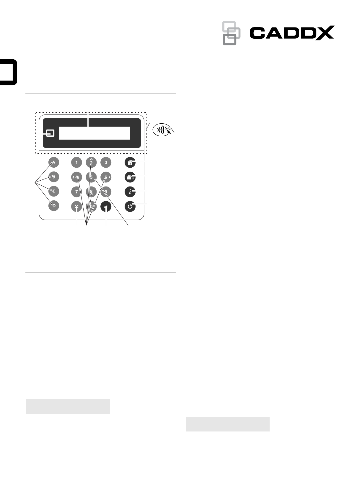
In Programming
Indicates that the system is being programmed. Press the
System Info (i) button to display the programming mode
details:
•Program Mode: The system is being programmed from
another keypad.
•Remote Program: The system is being programmed
remotely using the software or the Web page.
Zone Bypassed
Indicates that a zone is bypassed, either manually by a user, or
automatically during Arm Stay. Press the System Info (i) button
to show more details:
•Zone in Bypass | Zone number and name
•Zone Auto Bypassed | Zone number and name
System Not Ready
A zone is in an active state. Press the System Info (i) button to
display the active zone number and name.
Ready, Zones Open
The status is shown if a zone is in active state, but its partition
is configured for force arming, so it automatically bypasses the
active zone when arming. Press the System Info (i) button to
display the active zone number and name.
See also “Zone Bypassed” above.
Stay Armed and Away Armed
The following armed statuses can be shown:
•Stay Armed, Away Armed: A single partition is armed
•Stay Armed: X/Y, Away Armed: X/Y: X of Y partitions are
armed.
Press the System Info (i) button to display a list of partitions
with their current statuses. See “Partition status” on page 3 for
details on partition status.

P/N 466-5559-EN • REV E • ISS 15OCT21 9 / 12
System Ready
The system is ready to arm.
Programming
For full system programming, refer to xGenConnect Installation
and Programming Guide.
Specifications
Compatibility
xGenConnect panel series
Code combinations
10 000 to 100 000 000 (4 to 8 digits)
There are no invalid code combinations.
Voltage
9 to 15 VDC (provided by panel)
Current consumption (at 13.7 V DC)
Nominal
NXG-1830-EUR, NXG-1831-EUR: 90 mA
NXG-1832-EUR, NXG-1833-EUR: 130 mA
Minimal (all lights off)
NXG-1830-EUR, NXG-1831-EUR: 35 mA
NXG-1832-EUR, NXG-1833-EUR: 40 mA
Maximum
NXG-1830-EUR, NXG-1831-EUR: 160 mA
NXG-1832-EUR, NXG-1833-EUR: 200 mA
Input
Resistive, wiring compliant with
xGenConnect panel inputs
Output
NXG-1832-EUR, NXG-1833-EUR only
Open collector type
Internal 10 kΩ pullup to Main PWR line
Max. load for OC sink
100 mA
Max. voltage connected
externally
16 VDC
Overcurrent protection
Built in
Mifare reader
NXG-1832-EUR, NXG-1833-EUR only
Carrier frequency
13.560 MHz
Bandwidth
1.696 MHz
Maximum power output
42 dBμA/m
Supported cards
NXG-180x-5 (compatible with Mifare
DESFire EV2, EV3)
Wiring
xGen 4-wire bus
Mounting height
≤2 m
Dimensions (W × H × D)
133 x 130 x 25 mm
Colour
NXG-1830-EUR, NXG-1832-EUR: White
NXG-1831-EUR, NXG-1833-EUR:
Anthracite
Weight
0.3 kg
Operating temperature
−10 to +50°C
Maximum relative
humidity
95% noncondensing
Serviceable parts
There are no serviceable parts
Regulatory information
Manufacturer
Placed on the market by:
Carrier Fire & Security Americas Corporation Inc.
13995 Pasteur Blvd
Palm Beach Gardens, FL 33418, USA
Authorized EU manufacturing representative:
Carrier Fire & Security B.V.
Kelvinstraat 7, 6003 DH Weert, Netherlands
Product warnings
and disclaimers
THESE PRODUCTS ARE INTENDED FOR
SALE TO AND INSTALLATION BY QUALIFIED
PROFESSIONALS. CARRIER FIRE &
SECURITY CANNOT PROVIDE ANY
ASSURANCE THAT ANY PERSON OR ENTITY
BUYING ITS PRODUCTS, INCLUDING ANY
“AUTHORIZED DEALER” OR “AUTHORIZED
RESELLER”, IS PROPERLY TRAINED OR
EXPERIENCED TO CORRECTLY INSTALL
FIRE AND SECURITY RELATED PRODUCTS.
For more information on warranty disclaimers and
product safety information, please check
https://firesecurityproducts.com/policy/product-
warning/ or scan the QR code.
Certification
EN 50131-3
Security Grade 2, Environmental class II
Tested and certified by Telefication B.V.
European Union
directives
NXG-1830-EUR, NXG-1831-EUR: Carrier Fire &
Security hereby declares that this device is in
compliance with the applicable requirements and
provisions of the Directive 2014/30/EU and/or
2014/35/EU. For more information see
firesecurityproducts.com
NXG-1832-EUR, NXG-1833-EUR: Carrier Fire &
Security hereby declares that this device is in
compliance with the applicable requirements and
provisions of all applicable rules and regulations,
including but not limited to the Directive
2014/53/EU. For more information see:
firesecurityproducts.com
REACH
Product may contain substances that are also
Candidate List substances in a concentration
above 0.1% w/w, per the most recently published
Candidate List found at ECHA Web site.
Safe use information can be found at
https://firesecurityproducts.com/en/content/intrusi
on-intro
2012/19/EU (WEEE directive): Products marked
with this symbol cannot be disposed of as
unsorted municipal waste in the European Union.
For proper recycling, return this product to your
local supplier upon the purchase of equivalent
new equipment, or dispose of it at designated
collection points. For more information see:
recyclethis.info.
Product
documentation
Please consult the following weblink to retrieve
the electronic version of the product
documentation.
This link will guide you to the EMEA regional
contact page. On this page you can request your
login to the secured web portal where all manuals
are stored.
https://firesecurityproducts.com/en/contact
Contact information
www.firesecurityproducts.com/en/page/caddx

10 / 12 P/N 466-5559-EN • REV E • ISS 15OCT21

P/N 466-5559-EN • REV E • ISS 15OCT21 11 / 12

12 / 12 P/N 466-5559-EN • REV E • ISS 15OCT21
Table of contents
Other CADDX Keypad manuals

CADDX
CADDX RANGER 9060E User manual

CADDX
CADDX Ranger 9050 User manual

CADDX
CADDX RANGER 9060E User manual

CADDX
CADDX NX-148 User manual

CADDX
CADDX NX-148 User manual

CADDX
CADDX NXG-183 EUR Series Assembly instructions

CADDX
CADDX Ranger 9050 User manual

CADDX
CADDX NX148-E User manual

CADDX
CADDX Ranger 9060E LCD User manual

CADDX
CADDX Ranger 9050 User manual