Instruction Manual
ROGERS KNW SERIES OIL-FREE
ROTARY SCREW AIR COMPRESSORS
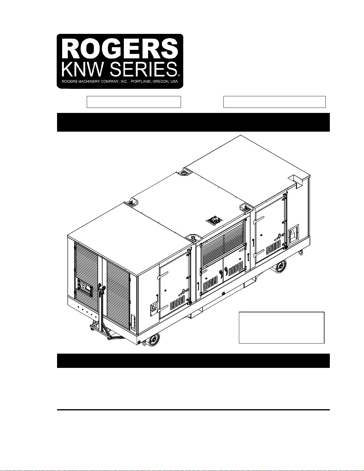
MODEL: GPKD-1550-H
NOTE: A companion publication, “Description of Operations” (e.g. K2A075A) for the
HMI/PLC programs, contains detailed instructions on HMI operation and
compressor controls. A separate publication from Caterpillar “SEBU9106-14”
details the operation and maintenance of the C15 and C18 Diesel engine.
Revisions
Update from R&M Revision to H Revision
1. General Description ................................6
1.1. Compressor...............................................6
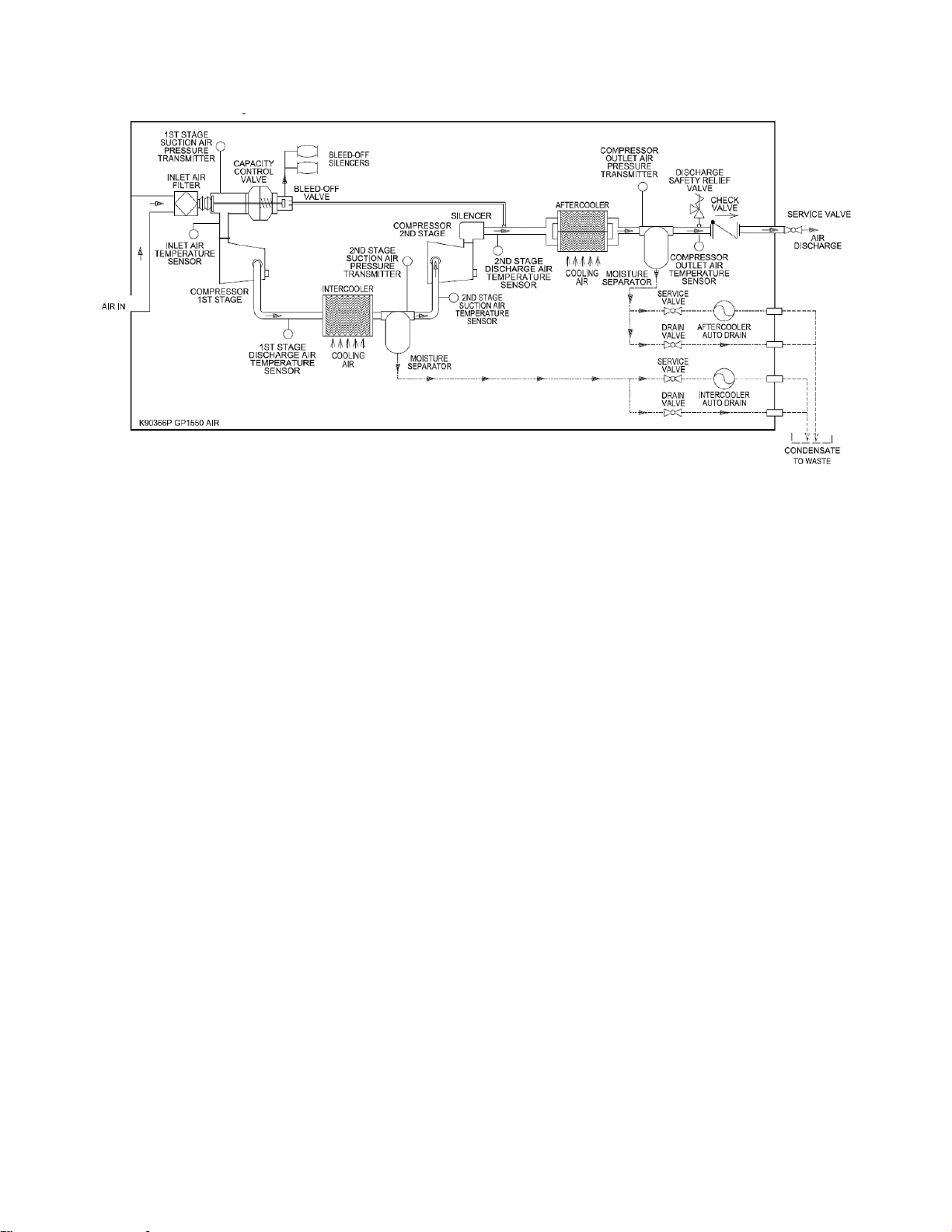
1.2. Compressed Air Flow................................7
1.3. Cooling Air Flow ........................................8
1.4. Oil Flow for Lubrication..............................9
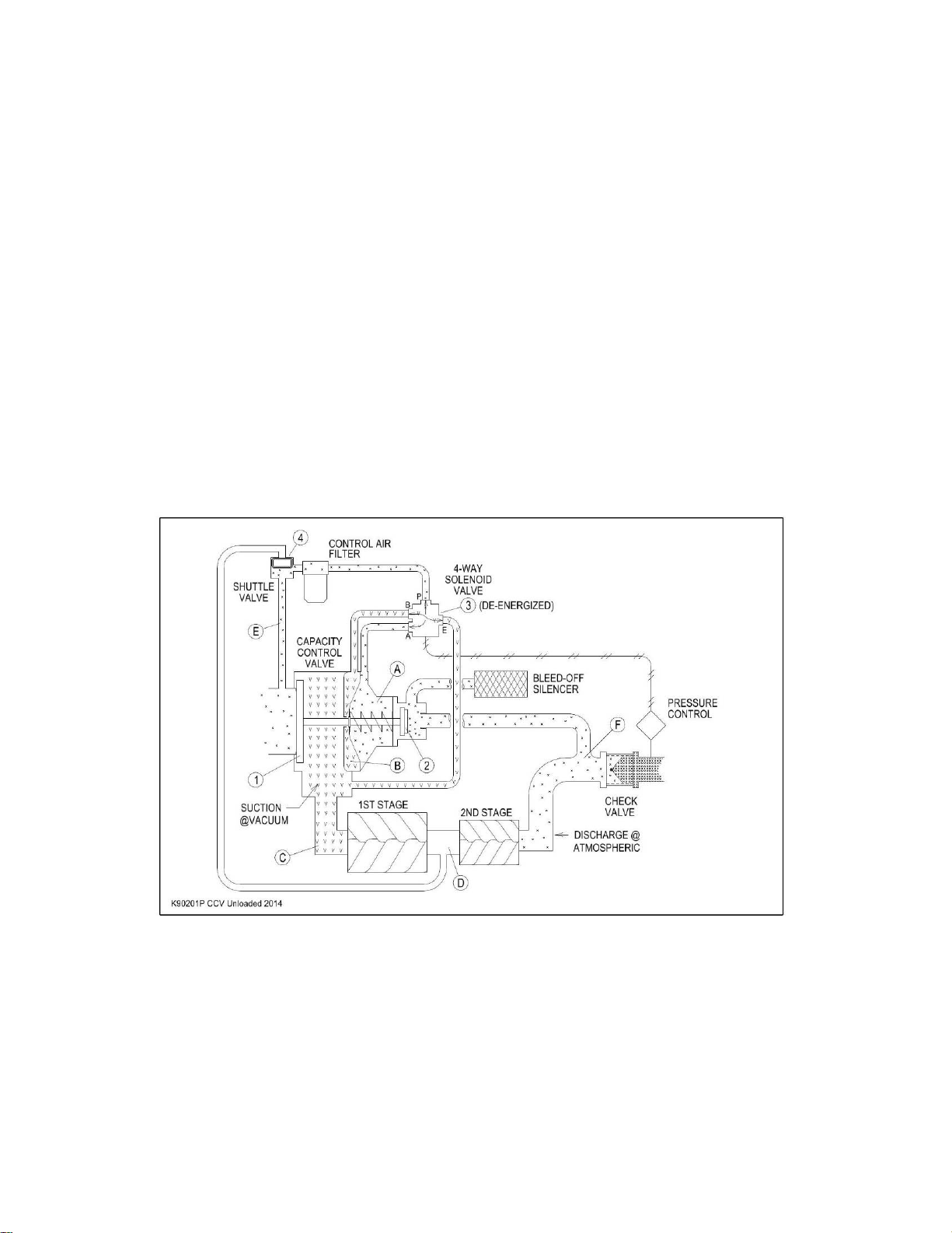
1.5. Capacity Control System.........................10
1.6.Monitoring and Limiting Devices .............12
1.7. Alerts and Alarms....................................13
1.8. Component Locations .............................14
2. Installation..............................................23
2.1. Inspection................................................23
2.2. Handling ..................................................23
2.3. Foundation ..............................................23
2.4. Location...................................................24
2.5. Cooling Air...............................................24
2.6. Compressor Air Outlet Piping..................24
2.7. Air Receiver.............................................26
2.8. Wiring ......................................................27
3. Start-Up...................................................28
3.1. Pre-start Checks......................................28
3.2. Initial Start-up..........................................30
4. Operating Instructions..........................30
4.1. Starting the Compressor .........................30
4.2. Stopping the Compressor .......................31
4.1. Automatic Stop........................................31
5. Electrical Controls.................................32
5.1. Compressor Control Panel......................32
HMI Maintenance............................................33
5.2. Programmable Logic Controller.............. 33
6. Maintenance........................................... 33
6.1. Daily........................................................ 34
6.2. Weekly .................................................... 34
6.3. Every 250 Service Hours........................ 35
6.4. Monthly.................................................... 35
6.5. Every 500 Service Hours or 3 Months.... 35
6.6. Every 2000 Service Hours...................... 35
6.7. Yearly...................................................... 35
6.8. Every 2500 Service Hours ...................... 36
6.9. Every 3000 Service Hours or 3 Years .... 36
6.10. Every 4000 Service Hours...................... 36
6.11. Every 5000 Service Hours ...................... 37
6.12. Every 6000 Service Hours or 3 Years .... 37
6.13. Every 10,000 Service Hours................... 37
6.14. Every 12,000 Service Hours or 6 Years . 37
6.15. Lubrication Oil......................................... 37
6.16. Filters ...................................................... 38
Inlet Air Filter (Compressor and Engine)........ 38
Compressor Oil Filter...................................... 38
Sump Breather ............................................... 39
Control Air Filter.............................................. 39
Engine Oil Filter.............................................. 39
DEF Manifold Filter......................................... 39
Diesel Exhaust Fluid Filter.............................. 39
Fumes Disposal Filter Element....................... 39