Donaldson UFM-T100H User manual

UFM-T100H
US
ES
CA
TM
Power
Test
Alarm

A
B
C
D
H
L
P
O
Q
R
U
V
W
X
N
M
G
I
J
K
S
T
E
F

Test
Power
Alarm
9
3
4
Test
Power
Alarm
1
5
2
Power
Alarm
Test
Test
Power
Alarm
6
78
Power
Alarm
Test
12
Power
Alarm
Test
Power
Alarm
Test
10 11
max 40 psi
US

Potential free contact max. 48V DC-relay
Potential free contact max. 230V AC-relay
Programmer connection
Alarm connection (potential free contact)
1
3
22
3
1
View on plug View on socket
Diode-suppressor
max. 92 mA
max. 92 mA
Interference-protection condenser
47 nF - 100 nF (suitable voltage)
3
4
3
4
+
-
13

US 6... 10
Warranty 11

6
US
Functional elements For
y
our safte
y
ACover screws Pozidrive 1; 0.74 ft lbf
BCover with heater
CLED
Light On: On
Light Flashing: Error
DTest button
ECover
FFixing screw
GRibbon cable
HInlet opening G1” ISO 228/1
IPotential-free contact 3,4
JPower supply , contact 1,2
Attention 24VDC-Version !
Contact 1 +24VDC
Contact 2 0 VDC
KEarthing connection, PE
LKey area 2"
MM16x1,5 screw connection for potential-
free contact 3,4 (option)
NM16x1,5 screw connection for
power supply 1,2
OCollecting area seal
PCondensate collecting area
QMembrane
RDrain plug
SReplacement parts set
(without adapter T)
TMembrane adapter
UFastening holes for attachement to a
console (self-tapping screws,
DIN7990; D5,5mm; Lmax 20mm)
VScrews (4x) long
Torx®;19.2 ft lbf
WScrews (2x) short
Torx®;19.2 ft lbf
XDrain and drain adapter
You as operator / user of the unit should
make yourself familiar with the function,
installation and start-up of the unit
through these operation instructions.
It is essential that you follow these
safety notes and this information in
order to ensure trouble-free operation of
the unit.
A
ll safety information in always intended
to ensure your personal safety
The pressure and temperature of the
medium must match witch the details
given on type plate of the unit.
Installation work may only be carried
out by trained and experienced
specialists.
Disconnect the power supply when
carrying out electrical work.
Wear protective glasses, when
working with media under pressure.
Risk of explosion ! It is not permitted
to use this unit in areas at risk of
explosion or with explosive or
inflammable media.
It is forbidden to carry out any kind of
work on the pressure vessels and
piping this covering welding,
constructional changes, installation
work, etc. Breaking this rule means
extreme danger for you.
Clean the piping before carrying out
the installation work.
Make a visual check before the initial
start-up. There must be no external
damage visible.
Depressurize the system before
carrying out the installation work.
Use the unit for appropriate purpose!

7
US
The unit may only be used for its intended
purpose. These units are intended
exclusively for following purpose:
Draining condensate from
compressed air out compressors, air
chambers, filters and dryers.
A
ny other form of use or one going
beyond this shall be considered as
inappropriate. We shall have no liability
whatsoever for any damage incurred as a
result .
Appropiate use
Notes for starting up
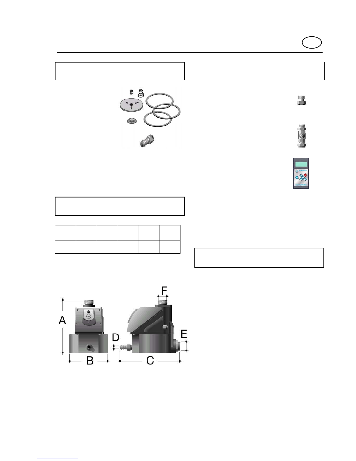
The inlet piping must have a internal
diameter of at least 0.74" to ensure
optimum bleeding of the condensate
drain if condensate gets in (1).
The inclination of the unit may not
exceed an angle of +/- 5° in both axles
(1/2).
It is recommended that a ball valve is
installed between the inlet piping and
the condensate drain and also
between the air shuttle line and the
pressure vessel (1/8).
Connecting two pressure vessels to
one condensate drain is wrong and
leads to functional problems with the
unit (3). Ensure that each pressure
vessel has its own drain.
Make sure that the chosen power
supply matches with the power supply
of the rating on the name plate.
After installation the isolation must be
mounted (4).
Ensure that no water pockets are
formed in the piping (5). Trapped air
prevents the condensate from flowing
out of the drain.
Example of piping to remove water
from piping (6).
The information channel (programmer
interface) provides the option to call
up or amend the units settings (7).
When using the rear condensate inlet
it is absolutely essential to use an air
shuttle line (8).
Pay attention that the top area of the
condensate drain is cleaned. Existing
labels on this area must be removed.
The condensate drain is ready for
operation if the power supply is
connected and the LED lights (9) and
pressure and condensate are applied.
Connect a hose (internal diameter
1/2") to the condensate drain and
the outlet adapter (10).
When the test button is pressed the
unit must audibly blow out condensate
or air (11).

8
Notes for electrical
connection
Strip the insulation off 6 inches of the
cable.
The unit only operates when power is
supplied and with the protective
strip connected. The installation
must be carried out as per VDE 100
[NEC] .
Connection values :
230VAC +/-10% 50Hz or
110VAC +/-10% 60Hz or
24VDC +/-10%
Attention: See also name plate
Provide an easily accessible means to
cut off the power.
Only use the PG screwed connection
for an installation with a flexible cable.
Remove the PG screwed connection
when using a hose with a screwed
connection. Screw fittings approved
by VDE or UL are to be used here.
US
Condensate flows through the
condensate inlet Fand collects in the
collecting area O. The membrane is
closed off by the system pressure .
When the moisture sensor detects liquid.
the pressure is released on membrane P
which then opens, and the condensate is
driven out by the system pressure. The
Membrane closes before air can escape.
Function
In the heater are line resistance are
installed, that gives out heat.
The heat is transfer by the conducted
heater on the aluminium housing.
The control of the heater with
temperature sensors is integrated.
One temperature sensor switches the
heater on when the ambient temperature
is falls under approx. 43°F.
A
n other temperature sensor protects the
heater against overheating. The cut-off
temperature is approx. 140°F.
The packing material and the unit
itself and its accessories are
produced from recyclable materials.
Separating the remaining materials in
an appropriate way helps in the
recycling of materials .
Protection of the
enviroment

9
Informationes concerning
maintenance
The unit requires very little
maintenance. Parts subject to wear
should be replaced at least every
year. (set of replacement parts)
The points marked in Fig. 12 must be
cleaned if they get dirty or if there is
an error. Note the safety stipulations.
The unit must be depressurized and
electrical disconnected.
The heated cover do not need any
maintenance.
Self-tapping screws must be
inserted without any force into the
existing thread to follow it. It is
essential to first turn the screw a
little to the left to find the start of
the thread when doing up the
screw. If the screw is done up
incorrectly, a new thread is formed
on top of the old one. This can
destroy the existing thread.
US
Error display:
LED flashes. An alarm message is given
if the potential contact was connected.
Cause
Sensor damp or unit flooded.
Reaction of the unit:
The potential free contact opens.
The unit opens each 30sec. until the
sensor is free of condensate and the unit
returns automatically back to normal
operation.
Error
Operating Pressure: 12 - 250 psi
Operating Temperature: +34°F to 140°F
Power supply *: 230V 50Hz or
110V 60Hz or
24VDC
*Depends on the version of the unit.
See also name plate.
Overvoltage category: II
Industrial mains
systems
Tolerance Voltage: +/-10%
Power consumption: 5VA
Potential-free Contact: max. 300 VDC
max. 247 VAC
electronic relay max. 0,092 A
(error = contact open)
A
mbient temperature: -4°Fto +140°F
(with insulation)
Technical Data
Maximum
compressor rating
Wight
empty
3600 cfm 8.2 lbs
If the error occurs again, it is essential to
doubt, please contact our after sales
service section.

10
US
Dimensions
ABCDEF
8.0 5.9 9.4 1/2" G3/4 G1
Guarantee
The guarantee becomes invalid if:
the operating instructions were not
followed with respect to installation
and initial commissioning
the unit was not operated properly and
appropriately,
the unit was operated when it was
clearly defective,
the unit was not operated within the
permissible technical parameters,
not authorised constructional changes
were made to the unit or if parts of the
unit that may not be opened were
dismantled
Spare parts
Set of replacement
parts subject to
wea
r
Outlet adapter
Please state in all cases the type
designation of the condensate drain when
ordering spare parts.
Accessories
Screwed connection with
1“ – 3/4“ union nut
Screwed connection with
ball valve
Programmer
Please state in all cases the type
designation of the condensate drain when
ordering spare parts.

11
Donaldson Company, Inc. warrants it Refrigerated Dryers, Desiccant Dryers and Chillers
are free from defects in materials and workmanship for two years from date of invoice. All
other Donaldson Company, Inc. products (filters, drains, aftercoolers, oil/water separators,
spare parts, and components) are warranted to be free from defects in materials and
workmanship for one year from date of invoice.
The Donaldson Company, Inc. Warranty excludes damages due to: corrosion, lack of
proper maintenance, incorrect installation, modification, or misapplication of equipment.
Routine maintenance or adjustments required under normal operation as outlined in the
Donaldson Company, Inc. (Ultrafilter & AirCel®) operation and maintenance manuals are
not covered under warranty.
After Donaldson Company, Inc. has been given adequate opportunity to remedy any
defects in material or workmanship in accordance with Donaldson Company, Inc.
Warranty Policy and Procedures, Donaldson Company, Inc. retains the sole option to
accept return of the goods, with freight paid by the purchaser, and to refund the purchase
price for the goods after confirming the goods are returned undamaged and in usable
condition. Such a refund will be the full extent of Donaldson Company, Inc’s. liability.
Donaldson Company, Inc. shall not be liable for any other costs, expenses or damages
whether direct, indirect, special, incidental, consequential or otherwise. The terms of this
warranty may be modified only by a special warranty document signed by Director,
General Manager, or Vice President of Donaldson Company, Inc.
THERE EXIST NO OTHER REPRESENTATIONS , WARRANTIES OR GUARANTIES
EXCEPT AS STATED IN THIS PARAGRAPH AND ALL OTHER WARRANTIES,
INCLUDING MERCHANTABILITY AND FITNESS FOR A PARTICULAR PURPOSE,
WHETHER EXPRESSED OR IMPLIED ARE HEREBY EXPRESSLY EXCLUDED AND
DISCLAIMED.
Donaldson Compressed Air & Gas Warranty

Technical alterations reserved!
Sous réserve de modifications technicques
Alteraciones técnicas reservadas
UFM-T100H_US/R03/2008/06
Donaldson Company, Inc.
Compressed Air & Gas
P.O. Box 1299
Minneapolis, MN 55440-1299 U.S.A
Tel 800.543.3634
Fax 770-448-3854
www.donaldson.com
IOM_DO_DF_US_R02_D071026:Bedienungsanleitung 17.06.2008 14:04 Seite 20
Table of contents
Popular Air Compressor manuals by other brands

Mattei
Mattei AC 6000 Series Instruction, use and maintenance manual

Axiom
Axiom ZEUS user manual

Scheppach
Scheppach HC24-8 Translation of original instruction manual

Fini
Fini HYPRO5-165 Operator's manual

Certa
Certa CT180ARCMPA quick start guide

Clarke
Clarke AIRMASTER 18/200 Operation & maintenance instructions