www.SteamPoweredRadio.Com
(
Bil
.....
~ ~
1(1
~
1:0
0
uo
•l'O
-
-
....
'"'"'
•--
""
' li.~w_j,~
::i
~
·"
....
-~
.....,
-·
~·
~
Distribution Amplifier
Model 120
("
I
NP
UT
OUTPUT
OOTPVT
'"''JT!tO,JTPIJT
INPUT
OUTl>OT
TE
"
• •
....
• •
G
A!
H
GA
IN
.
,.
Glo.l
N G
A.IN
.2
.3
• .
4.
l
\,HO
tt
L GNO H
•
L GNO H
• •
L G
l<fO
H
•
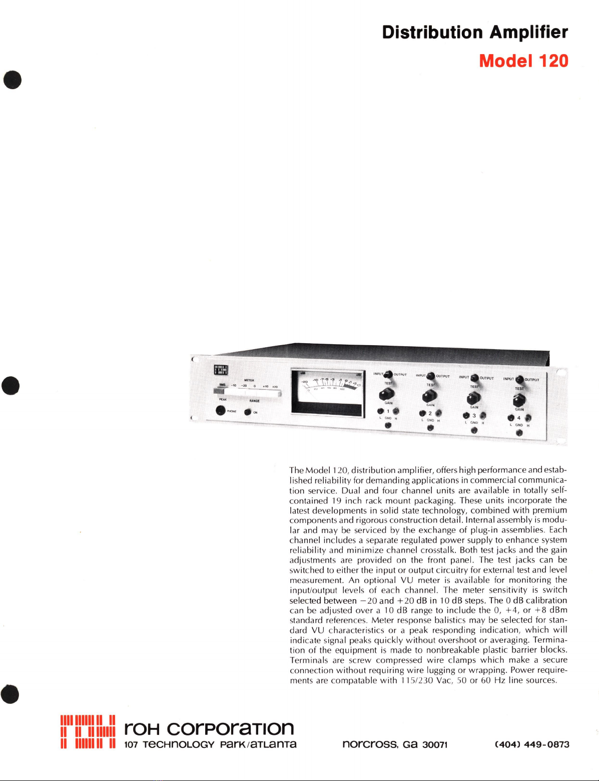
The
Model
1
20,
distribution
amplifier, offers high performanceand estab-
1
ished
reliability
for
demanding
applications in commercial
communica-
tion service. Dual and four channel units are available in totally self-
contained 19 inch rack
mount
packagin
g.
These units incorporate the
lat
es
t developments in solid sta
te
technology,
combined
with
premium
co
mponents and rigorous construction detail. Internal assembly
is
modu-
lar and
may
be
se
rviced by the exchange
of
plug-in assemblies.
Each
channel includes a separate regulated
power
supply to enhance system
reliab
ility
and
minimize
channel crosstalk. Both test jacks and the gain
adjustments are provided on the front panel. The test jacks
ca
n
be
switched to either the
input
or
output
circuitry
for external test and level
m
eas
urement. An optional
VU
meter
is
available for
monitoring
the
input/output
levels
of
each channel. The meter sensitivity
is
switch
selected between
-20
and +
20
dB in 10 dB steps. The 0 dB calibration
can be adjusted
over
a 10 dB range to
include
the 0,
+4,
or
+8
dBm
standard references.
Meter
response balistics may be selected for stan-
dard
VU
characteristics
or
a peak respo
nding
indication,
which
will
indicate signal peaks
qui
ckly
without
overshoot
or
averaging. Termina-
tion
of
the
equipment
is
made to nonbreakable plastic barrier blocks.
Termina
ls
are
sc
rew compressed
wire
clamps
which
make a
sec
ure
connection
without
requiring
wire
lugging
or
wrapping. Power require-
ments are compatable
with
11
5/
230
Vac,
50
or
60
Hz
line sources.
1111
1111
11111111
roH corPoraT1on
II
11111111
II
101
TecHnOLOGY ParK1aTLanTa
norcross.
Ga
30011
(404)
449-0873