www.SteamPoweredRadio.Com
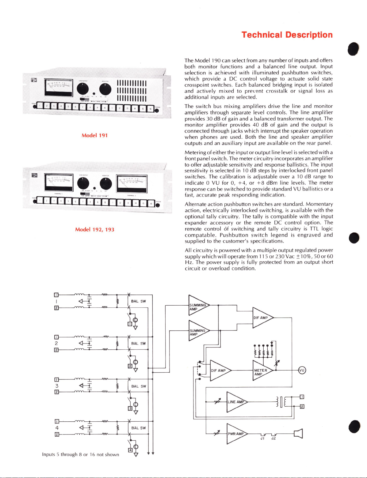
Model 191
·• ·I,1,I·1,t,1,1,I·I•I
··
I·1,,
,.
1
,,
1•I•·
Model
192
, 193
BAL
SW
Inputs 5 through 8
or
16 not shown
Technical Description
The
Model
190can select from any number
of
inputs and offers
both
monitor
functions and a balanced
line
output. Input
selection
is
achieved
with
illuminated pushbutton switches,
which
provide a DC control voltage to actuate solid state
crosspoint switc
hes.
Each
balanced bridging
input
is
isolated
and
actively
mixed
to
pre,
·e
nt
crosstalk
or
signal loss
as
additional inputs are selected.
The switch bus
mixing
amplifiers drive the line and
monitor
amplifiers through separate level controls. The line
amplifier
provides 30 dB
of
gain and a balanced transformer output. The
monitor
amplifier provides 40 dB
of
gain and the
output
is
connected through jacks
which
interrupt the speaker operation
when phones are used. Both the line and speaker
amplifier
outputs and an auxiliary
input
are available on the rear panel.
Metering
of
eitherthe
input
or
output
Iine level
is
selected
with
a
front panel switch. The meter
circuitry
incorporates
an
amplifier
to offer adjustable sensitivity and response ballistics. The input
sensitivity
is
selected in 10 dB
steps
by interlocked front panel
switches. The calibration
is
adjustable over a 10 dB range to
indicate 0 VU for 0,
+4,
or
+8
dBm line levels. The meter
response
ca
n
be
switched to provide standard VU ballistics
or
a
fast, accurate peak responding indication.
Alternate action pushbutton switches are standard. Momentary
action, electrically interlocked switching,
is
available
with
the
optional tally circuitry. The
tally
is
compatible
with
the
input
expander accessory or the remote DC control option. The
remote control
of
switching and tally
circuitry
is
TTL logic
compatable
.
Pushbutton
switch
legend
is
engraved
and
supplied
to
the customer's specifications.
All
circuitry
is
powered
with
a
multiple
output
regulated
power
supply
which
will
operate from 115
or
230 Vac ±10%, 50 or 60
Hz
. The
power
supply
is
fully
protected from
an
output short
circuit
or
overload condition.
•
•