Rohm BD71631QWZ-EVK-001 User manual

1/13
© 2021 ROHM Co., Ltd.
No. 64UG016E Rev.001
MAY.2021
User’s Guide
Battery Charger Series
Linear Charger for Low Voltage Battery
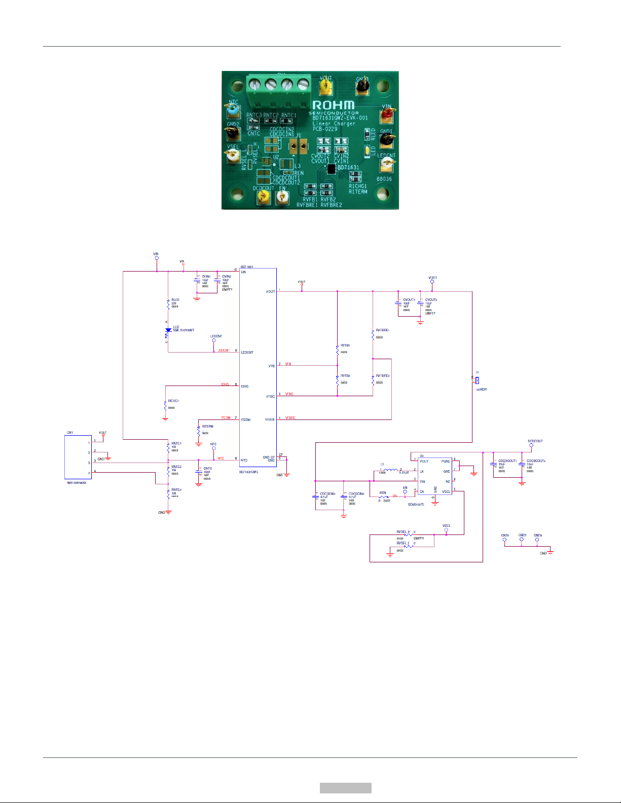
BD71631QWZ EVK
BD71631QWZ-EVK-001 (5V→4.2V, 0.1A)
Introduction
This user’s guide provides the necessary steps to operate the EVK of ROHM’s BD71631QWZ linear charger for low charge
voltage battery. This include the external parts, operating procedures, and application data.
Description
This EVK is for evaluating the linear charging IC BD71631QWZ, and charges 4.2V from the 5V input voltage. BD71631QWZ
accepts a power supply input range of 2.9V to 5.5V and generates a charging battery voltage ranging from 2.0V to 4.7V using
external resistors. If the charging current is VIN ≥ 4 V, it can be used up to 300 mA under the condition of VIN-VOUT ≥ 1 V and
up to 100 mA under the condition of VIN-VOUT ≥ 0.3 V. If 2.9 V ≤ VIN ≤ 5.5 V, it can be used up to 30 mA under the condition of
VIN-VOUT ≥ 0.3 V. The charging current can be set with an external resistor. The termination current can be set from 50 μA to 10
mA using external resistors. Additional protection functions include a built-in Fixed 10-hour Safety Timer, UVLO (Under Voltage
Lock Out), TSD (Thermal Shutdown Detection), and Battery Over Voltage Protection.
Application
Low Voltage Battery Products
Li-ion 1Cell Battery Products
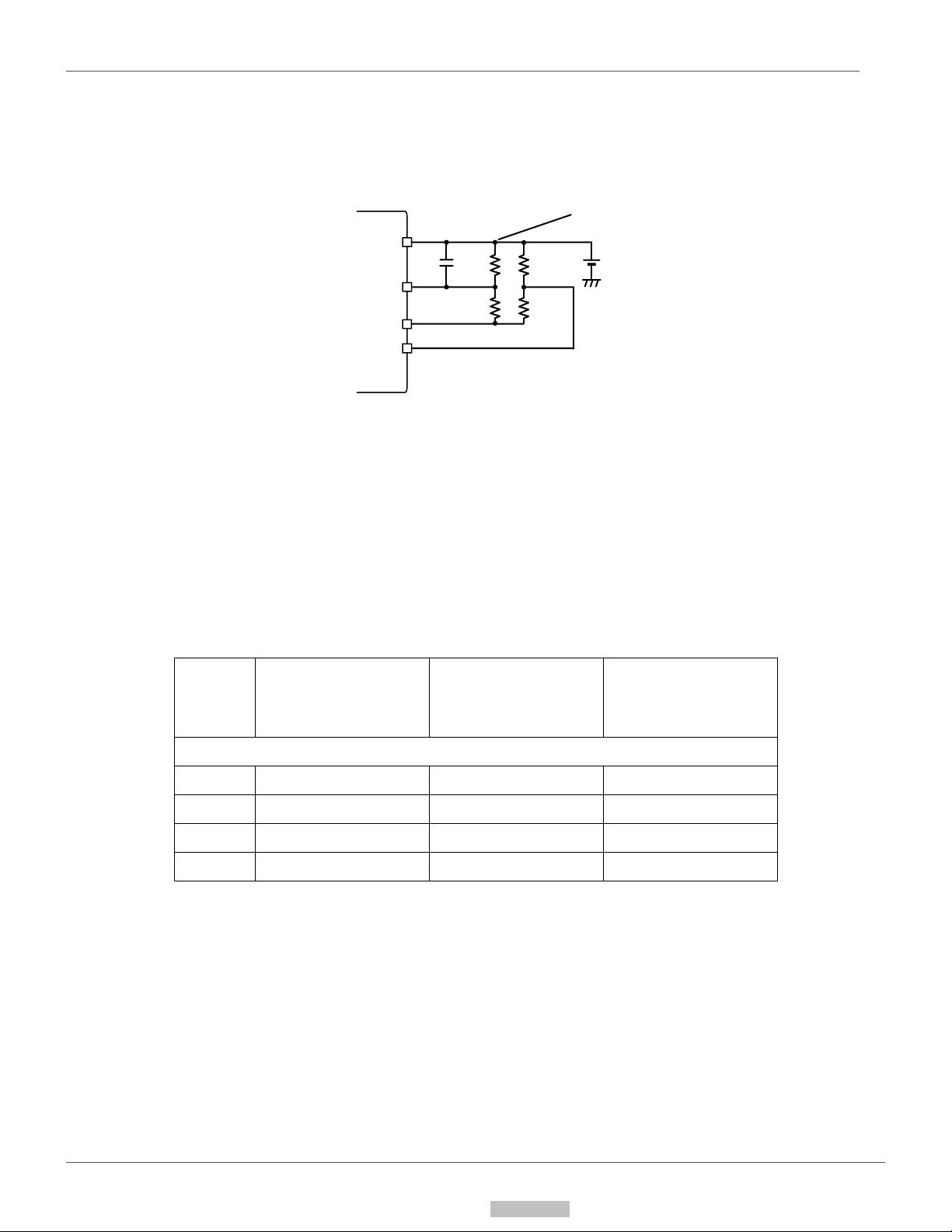
Operating Limits
Table 1. Operating Limits
Parameter
Symbol
Min
Typ
Max
Units
Conditions
Input Voltage
VIN
4.5
5.0
5.5
V
Charge Voltage
VCHG
4.2
V
RVFB1=180kΩ, RVFB2=30kΩ
Pre Charge Voltage
VPRE
0.7
V
Re Charge Voltage
VRECHG
3.0
V
RVFBRE1=120kΩ, RVFBRE2=30kΩ
Charge Current
ICHG
98
mA
RICHG1=5.1kΩ
Termination Current
ITERM
0.98
mA
RITERM=51kΩ
VOUT Leak Current
IBAT
0
1
µA
VIN=Open
Downloaded From Oneyac.com

2/13
© 2021 ROHM Co., Ltd.
No. 64UG016E Rev.001
MAY.2021
User’s Guide
BD71631QWZ-EVK-001
EVK
Figure 1. BD71631QWZ-EVK-001(Top View)
EVK Schematic
120k
180k
30k30k
5.1k
51k
U1
Figure 2. BD71631QWZ-EVK-001 Circuit Diagram
Operating Procedure
1. Turn off the DC power supply and connect the GND terminal of the power supply to the GND1 terminal of the EVK.
2. Connect the positive terminal of the DC power supply to the VIN pin of the EVK.
3. Connect the positive terminal of the DC power supply that can sink to the VOUT pin of the EVK.
4. Connect a current meter between the VOUT terminal of the EVK and the positive terminal of DC power supply of VOUT.
5. Connect a voltmeter between the VOUT terminal and GND terminal of EVK.
6. Turn on the DC power supply of VOUT.
7. Turn on the DC power supply of VIN. The power supply on the VOUT side is set to 4.2V or lower, charging will start and
current will flow through the ammeter.
(Caution) This EVK does not support hot plug. Do not perform hot plug test.
Downloaded From Oneyac.com

3/13
© 2021 ROHM Co., Ltd.
No. 64UG016E Rev.001
MAY.2021
User’s Guide
BD71631QWZ-EVK-001
Charging State
Below is a charging state of BD71631QWZ.
VBAT
Time
Charge
(CC) (CV)
Charge Current
Battery Voltage
IBAT
VCHG
ICHG
ITERM
Charge Stop
15 s
Charge
Stop
10 hour Safety Timer Counting
LED_OFF LED_ON LED_OFF
IPRE
= ICHG / 2
VPRE
LEDCNT
Figure 3. Charging profile
Charging stop section on the left in Figure 3 is in the state of SUSPEND in Figure 4, and charging is stopped.
In the Charge section, charging starts and the charging current IPRE or ICHG flows.
The Pre-charge current IPRE flows until the battery voltage reaches the Pre-charge voltage VPRE.IPRE is ICHG / 2 that is charged at
Constant Current (CC) and the charging current IPRE flows.
When the battery voltage reaches the Pre-Charge voltage VPRE, it is charged at Constant Current (CC) and the charging current ICHG
flows.
When the battery voltage reaches the VCHG voltage, it is charged at Constant Voltage (CV) and the charging current decreases.
When the charging current reaches the Termination current ITERM, it will be in the TOP-OFF state, and after 15 seconds have
passed, it will be in the DONE state.
SUSPEND
CHARGE
①
TOP_OFF
②
③
TEMP_ERROR_1
TEMP_ERROR_2
⑦
⑧
BATTERY_ERROR
⑤
DONE
④
⑥
ALL State ⑨
⑤
⑤⑤
⑦
⑧
Figure 4. Charging state
Downloaded From Oneyac.com

4/13
© 2021 ROHM Co., Ltd.
No. 64UG016E Rev.001
MAY.2021
User’s Guide
BD71631QWZ-EVK-001
Table 2. Charging state transition condition
No.
State transition
Condition
①
SUSPEND -> CHARGE
UVLO, TSD not detect
and VIN > VBAT+0.3 V
and VBAT OVP not detect
and Temp Error not detect
Continue to satisfy the condition for 25 ms
②
CHARGE -> TOP_OFF
Charge current < ITERM
Continue to satisfy the condition for 25 ms
③
TOP_OFF -> CHARGE
Charge current > ITERM
Continue to satisfy the condition for 25 ms
④
TOP_OFF -> DONE
Continue to satisfy the ③ condition for 15 s
⑤
CHARGE or TOP_OFF or
TEMP_ERROR_1 or
TEMP_ERROR_2
-> BATTERY ERROR
VBAT OVP detect
or 10 hours safety timer expired
⑥
DONE -> CHARGE
VBAT < Re-charge voltage
Continue to satisfy the condition for 25 ms
⑦
CHARGE -> TEMP_ERROR_1 or
TOP_OFF -> TEMP_ERROR_2
Temp Error detect
Continue to satisfy the condition for 25 ms
⑧
TEMP_ERROR_1 -> CHARGE or
TEMP_ERROR_2 -> TOP_OFF
Temp Error not detect
Continue to satisfy the condition for 25 ms
⑨
ALL State -> SUSPEND
UVLO, TSD detect
or VIN < VBAT+0.3 V
Table 3. Safety timer and Internal control settings for each state of LEDCNT
State
Battery charge
10 hours safety timer
LEDCNT
SUSPEND
Stop
Stop and reset
Hi-Z
CHARGE
Charge
Count
Low
TOP_OFF
Charge
Count
Low
DONE
Stop
Stop and reset
Hi-Z
BATTERY_ERROR
Stop
Stop and reset
Hi-Z
TEMP_ERROR_1
Stop
Count
Hi-Z
TEMP_ERROR_2
Stop
Count
Hi-Z
Downloaded From Oneyac.com

5/13
© 2021 ROHM Co., Ltd.
No. 64UG016E Rev.001
MAY.2021
User’s Guide
BD71631QWZ-EVK-001
Peripheral Components Setting
1. Charging voltage (VCHG), Recharge voltage (VRECHG) setting
The resistance values of the charging voltage VCHG and re-charge voltage VRECHG can be set by the following formula.
Battery
VOUT
VFBG
VFB
VFBRE
RFB1
RFB2
RFBRE1
VCHG
RFBRE2
CSPU
VRECHG
,
Figure 5. Resistor setting of VCHG and VRECHG
The charge voltage is determined as follows :
The re-charge voltage is determined as follows :
About total feedback resistance, the following is a reference example of operation settings. .
Table 4. Resister reference value
Charge
Condition
VCHG = 4.2 V
VCHG = 2.2 V
VCHG = 4.2 V
VRECHG = 3.0V
VRECHG = Disenable
VRECHG = 3.9 V
Resistor value [Ω]
RFB1
180 k
200 k
600 k
RFB2
30 k
75 k
100 k
RFBRE1
120 k
-*
1.1 M
RFBRE2
30 k
-*
200 k
*VFBRE pin connect to GND
A capacity of 10μF or more is required between the VOUT terminal and GND terminal of BD71631QWZ. Connect CSPU for
stable operation when the battery capacity is too small.
The capacitance of CSPU is determined as follows :
Downloaded From Oneyac.com

6/13
© 2021 ROHM Co., Ltd.
No. 64UG016E Rev.001
MAY.2021
User’s Guide
BD71631QWZ-EVK-001
About the current of the external resistor that generated by the FB terminal and FBRE terminal
Nch FET is built in between the VFBG terminal and the GND terminal.
When the VIN terminal is connected, the Nch FET turns on and current flows from the battery to the external resistor.
When the VIN terminal is disconnected, the Nch FET turns off and no current flows from the battery to the external resistor.
If the VFBRE terminal is connected to GND and recharging is disabled , the internal Nch FET will be turned off when charging is
completed even if VIN is connected.
2. Charge current, Termination current setting
The charging current ICHG can be set by the following formula using the external resistor RICHG1.
[mA]
The charging current can be set up to 300 mA (VIN ≥ 4 V, VIN-VOUT ≥ 1 V), 100 mA (VIN ≥ 4 V, VIN-VOUT ≥ 0.3 V), and 30 mA (2.9
V ≤ VIN ≤ 5.5 V, VIN-VOUT ≥ 0.3V). There is a limit to the voltage between VIN and VOUT in the usage range of the charging
current.
The termination current ITERM can be set by the following equation using the external resistor RITERM.
The termination current can be set from 50 μA to 10 mA.
[mA]
ICHG
RICHG1
RITERM
ITERM
Figure 6. Resistor setting of ICHG and ITERM
3. Charge Current vs Battery Temperature
It is possible to monitor the temperature of the battery using NTC thermistor.
The charging current is controlled by the battery temperature, as shown in the temperature profile in Figure 7.
It is set by the NTC thermistor and pull-up resistor in Figure 8.
The component constants can be set according to the voltage of the NTC terminal at each temperature.
Downloaded From Oneyac.com

7/13
© 2021 ROHM Co., Ltd.
No. 64UG016E Rev.001
MAY.2021
User’s Guide
BD71631QWZ-EVK-001
Charge current
[mA]
ICHG
NTC Temp []
48
2
Hys Hys
7 43
Figure 7. Charge Current vs Battery Temperature
NTC terminal voltage(VNTC_Cold、VNTC_Hot)
2 °C: 3.605 V
7 °C: 3.375 V
43 °C: 1.720 V
48 °C: 1.535 V
Figure 8. Resistor setting of NTC terminal
How to find the external resistance of the NTC terminal and the NCT constant is as follows.
When calculating RNTC and RNTCR1, firstly calculate the resistance voltage dividers VHot and VCold when charging stops with the
NTC thermistor temperature profile in Figure 7. The error of the %VCold and %VHot thresholds will depend on temperature
coefficient B of the chosen NTC thermistor resistor.
By simulated calculation, the resistance value is calculated so that the error of the NTC terminal voltage at each temperature
becomes small.
Battery
NTC
T
VIN = 5 V
10 kΩ
NCP03XH103F05RL
10 kΩ / B(25/50) = 3380k
RNTC
RNTC1
Downloaded From Oneyac.com

8/13
© 2021 ROHM Co., Ltd.
No. 64UG016E Rev.001
MAY.2021
User’s Guide
BD71631QWZ-EVK-001
Where the NTC thermistor resistance at the T_Cold and T_Hot temperatures must be resolved as follows:
VCold: The value of the voltage divided by the resistance at low temperature
VHot: The value of the voltage divided by the resistance at hot temperature
VNTC_Cold: Detection voltage of NTC terminal at low temperature . 3.605 V at Ta=2 °C
VNTC_Hot: Detection voltage of NTC terminal at high temperature. 1.535 V at Ta=48 °C
RNTC_Cold: NTC thermistor resistance at cold temperature
RNTC_Hot: NTC thermistor resistance at hot temperature
Ro: NTC thermistor resistance at Ta 25°C
B: B constant of NTC thermistor
T_Cold: Low temperature
T_Hot: High temperature
To: 25°C
Downloaded From Oneyac.com

9/13
© 2021 ROHM Co., Ltd.
No. 64UG016E Rev.001
MAY.2021
User’s Guide
BD71631QWZ-EVK-001
Parts list
Table 5. Parts list
Count
Parts No.
Type
Value
Description
Manufacturer
Part Number
Manufacturer
Size
[Unit: mm(inch)]
IC
1
U1
Charger
-
Linear Charger
BD71631QWZ-E2
ROHM
1.8 x 2.4
(0.071x0.094)
Capacitor
1
CVIN1
MLCC
4.7µF
16V, X5R, ±10%
GRM188R61C475KAAJD
MURATA
1608(0603)
1
CVOUT1
MLCC
1µF
25V, X5R, ±10%
GRM155R61E105KA12D
MURATA
1005(0402)
1
CNTC
MLCC
0.01µF
16V, B, ±10 %
GRM155B11C103KA01
MURATA
1005(0402)
2
CVIN2,
CVOUT2
MLCC
OPEN
-
-
-
-
Resistor
3
RLED,
RNTC1,
RNTC2
Resistor
10kΩ
1/10W, 50V,
±0.5%
MCR03EZPD1002
ROHM
1608(0603)
1
RICHG1
Resistor
5.1kΩ
1/10W, 50V,
±0.5%
MCR03EZPD5101
ROHM
1608(0603)
1
RITERM
Resistor
51kΩ
1/10W, 50V,
±0.5%
MCR03EZPD5102
ROHM
1608(0603)
1
RVFB1
Resistor
180kΩ
1/10W, 50V,
±0.5%
MCR03EZPD1803
ROHM
1608(0603)
1
RVFBRE1
Resistor
120kΩ
1/10W, 50V,
±0.5%
MCR03EZPD1203
ROHM
1608(0603)
2
RVFB2,
RVFBRE2
Resistor
30kΩ
1/10W, 50V,
±0.5%
MCR03EZPD3002
ROHM
1608(0603)
1
RNTC3
-
SHORT
-
-
-
-
LED
1
LED
-
LED
White, Clear
SML312WBCW1
ROHM
1608(0603)
Connector
1
J1
-
OPEN
-
-
-
-
1
CN1
Connector
4terminals
3.81mm pitch
MKDS 1/ 4-3,81
Phoenix
contact
15.23x 7.3
(0.6x0.29)
Optional parts (Boost converter)
1
U2
-
OPEN
-
-
-
-
1
L3
-
OPEN
-
-
-
-
2
CDCDCIN1,
CDCDCIN2
-
OPEN
-
-
-
-
2
CDCDCOUT1,
CDCDCOUT2
-
OPEN
-
-
-
-
3
REN,
RVSEL_H,
RVSEL_L
-
OPEN
-
-
-
-
The product and manufacturer names listed in the parts list are current at the time this user’s guide was prepared, and some parts
may not be available. Please select the equivalent product based on the characteristics listed in the table. Select a ceramic
capacitor with the same actual capacitance in consideration of the DC bias characteristics.
Downloaded From Oneyac.com

10/13
© 2021 ROHM Co., Ltd.
No. 64UG016E Rev.001
MAY.2021
User’s Guide
BD71631QWZ-EVK-001
Board Layout
EVK PCB information
Number of Layers
Material
Board Size
Copper Thickness
4
FR-4
46mm x 36mm x 1.6mm
1oz (35μm)
The layout of BD71631QWZ-EVK-001 is shown below.
Figure 9. Top Silkscreen Layout
(Top View) Figure 10. Top Layer Layout
(Top View)
Figure 11. Middle1 Layer Layout Figure 12. Middle2 Layer Layout
(Top View) (Top View)
Downloaded From Oneyac.com

12/13
© 2021 ROHM Co., Ltd.
No. 64UG016E Rev.001
MAY.2021
User’s Guide
BD71631QWZ-EVK-001
Reference Application Data
Figure 14. Charge Current vs VOUT Voltage Figure 15. Charge Voltage vs Input Voltage
Figure 16. VOUT Leak Current vs VOUT Voltage
(VIN = Open)
VIN = 5 V
ICHG = 100 mA
VCHG = 4.2 V
VRECHG = 3 V
VCHG = 4.2 V
Downloaded From Oneyac.com

5
%
ZZZURKPFRP
652+0&R/WG$OOULJKWVUHVHUYHG
Notice
ROHM Customer Support System
https://www.rohm.com/contact/
Thank you for your accessing to ROHM product informations.
More detail product informations and catalogs are available, please contact us.
Notes
The information contained herein is subject to change without notice.
Before you use our Products, please contact our sales representative
and verify the latest specifica-
tions :
Although ROHM is continuously working to improve product reliability and quality, semicon-
ductors can break down and malfunction due to various factors.
Therefore, in order to prevent personal injury or fire arising from failure, please take safety
measures such as complying with the derating characteristics, implementing redundant and
fire prevention designs, and utilizing backups and fail-safe procedures. ROHM shall have no
responsibility for any damages arising out of the use of our Poducts beyond the rating specified by
ROHM.
Examples of application circuits, circuit constants and any other information contained herein are
provided only to illustrate the standard usage and operations of the Products. The peripheral
conditions must be taken into account when designing circuits for mass production.
The technical information specified herein is intended only to show the typical functions of and
examples of application circuits for the Products. ROHM does not grant you, explicitly or implicitly,
any license to use or exercise intellectual property or other rights held by ROHM or any other
parties. ROHM shall have no responsibility whatsoever for any dispute arising out of the use of
such technical information.
The Products specified in this document are not designed to be radiation tolerant.
For use of our Products in applications requiring a high degree of reliability (as exemplified
below), please contact and consult with a ROHM representative : transportation equipment (i.e.
cars, ships, trains), primary communication equipment, traffic lights, fire/crime prevention, safety
equipment, medical systems, servers, solar cells, and power transmission systems.
Do not use our Products in applications requiring extremely high reliability, such as aerospace
equipment, nuclear power control systems, and submarine repeaters.
ROHM shall have no responsibility for any damages or injury arising from non-compliance with
the recommended usage conditions and specifications contained herein.
ROHM has used reasonable care to ensurHthe accuracy of the information contained in this
document. However, ROHM does not warrants that such information is error-free, and ROHM
shall have no responsibility for any damages arising from any inaccuracy or misprint of such
information.
Please use the Products in accordance with any applicable environmental laws and regulations,
such as the RoHS Directive. For more details, including RoHS compatibility, please contact a
ROHM sales office. ROHM shall have no responsibility for any damages or losses resulting
non-compliance with any applicable laws or regulations.
When providing our Products and technologies contained in this document to other countries,
you must abide by the procedures and provisions stipulated in all applicable export laws and
regulations, including without limitation the US Export Administration Regulations and the Foreign
Exchange and Foreign Trade Act.
This document, in part or in whole, may not be reprinted or reproduced without prior consent of
ROHM.
1)
2)
3)
4)
5)
6)
7)
8)
9)
10)
11)
12)
13)
Downloaded From Oneyac.com
This manual suits for next models
1
Table of contents
Other Rohm Batteries Charger manuals
Popular Batteries Charger manuals by other brands

Redarc
Redarc BCDC1220 user manual

Midtronics
Midtronics DCA-8000 quick start guide

ABSINA
ABSINA A800 user manual

EINHELL
EINHELL CE-BC 2 M Original operating instructions

VDC Electronics
VDC Electronics BatteryMINDer Plus 1510 instructions

CEMONT
CEMONT VELOX 520.2 CD.2 Safety instruction for use and maintenance