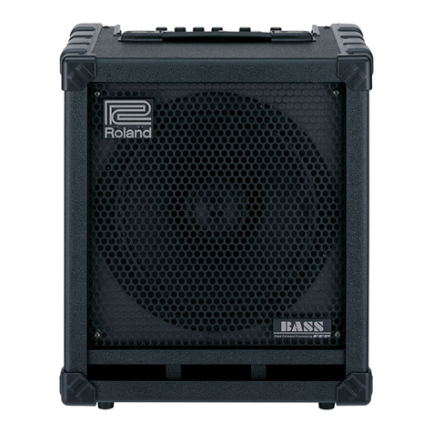
SERVICE NOTES
Issued by RJA
Copyright © 2013 Roland Corporation
All rights reserved. No part of this publication may be reproduced in any form without the written permission
of Roland Corporation.
CC-OKN17058881E0
Jul. 2013 AC-40
Table of Contents
Cautionary Notes ..............................................................2
Specifications .....................................................................3
Location of Controls .........................................................4
Location of Controls Parts List........................................5
Exploded View (All) .........................................................6
Exploded View (All) Parts List........................................7
Plane View (1)....................................................................8
Plane View (1) Parts List ..................................................8
Plane View (2)....................................................................9
Plane View (2) Parts List ..................................................9
Exploded View (Fig. A)..................................................10
Exploded View (Fig. A) Parts List ................................11
Plane View (Fig. A) .........................................................12
Plane View (Fig. A) Parts List........................................13
Application Sites for EVA Packing Cushions .............14
Parts List ...........................................................................16
Verifying the Version......................................................18
Test Mode .........................................................................18
Input/Output Level Test (for Reference) ....................19
Wiring Diagram/Block Diagram..................................20
Circuit Board (Main Board) ...........................................22
Circuit Diagram (Main Board: 1/3)..............................24
Circuit Diagram (Main Board: 2/3)..............................26
Circuit Diagram (Main Board: 3/3)..............................28
Circuit Board (GT Input, Panel, Jack, Mic Input Board)
............................................................................................30
Circuit Diagram (GT Input Board) ...............................31
Circuit Diagram (Panel Board)......................................32
Circuit Diagram (Jack Board) ........................................34
Circuit Diagram (Mic Input Board) ..............................36
