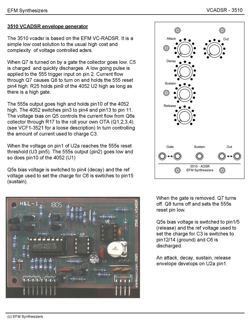
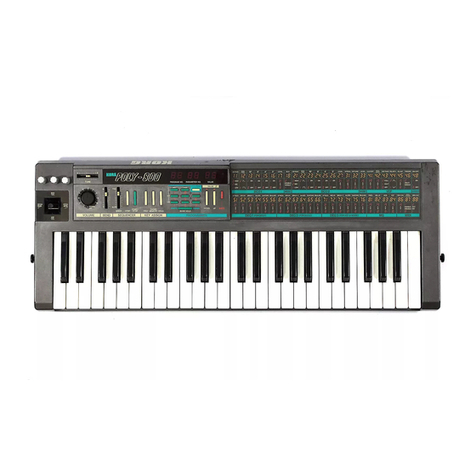
Roland TB-303 Operating and maintenance manual

Feb.19,1982
TB-303 SERVICE mm
SPECIFICATIONS
TB-303
First Edition
PATTERN MEMORY CAPACITY
64: 8{PATTERN) x2(PATT. SECTION) x4
(PATT. GROUP ITt, lit, IV)
Contents: Pitch, Value, Accent, Slide
WIINIMUW STEP ^
'tM/TTi i-*z.-i/
STEPs/measofe
j- 1to 16 steps {2, 3or 4meier)
*Uo 15 stepiS {2, 3, 4or 5meter]
Scale
3octaves {PATTERN) w/TRANSPOSE
4Octaves (TRACK) w/Kev shift
TRACK MEMORY CAPACITY
64 measures/TRACK Total 256 measures (64 x1
tracks)
Ctmti'rus: Older. TRANSPOSE. DC^
TUNING Control: approx t700 cents (perfect
fitih)
TEMPO Control: [J-40 to 300)
CONNECTIONS
Output: Impedance lOkft
HeedphoTie: Impedance to 30fl
Gate Out: OFF :OV; ON: +12V
CV Out: +1 Vto +6V (1 voit/oct)
SYNC In: DIN conr\eclor
MIX In: Impedarvce lOOkfl
Gam: Urtity
POWER
6V: 16V battery x 4
9V: AC adaptor
80mA to 120mA
Dimensions: 300(W| x146(0) x55(H) mm
Weight: 1.0 kg
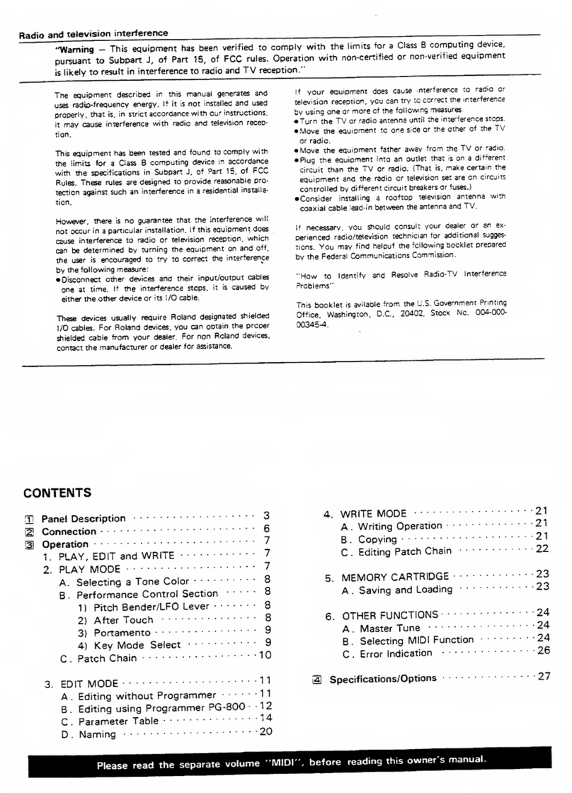
READ ''PRELIMINARY DIAGNOSIS" ON PAGE 7
BEFORE STARTING TRQUBLESHOOTmG
Pm. XlBTTOOW 50kB *2 O32^9774] --e«. xieiBOSOkA 1132193401
Pm. K16tBO-50kA U321 93401'
Poi. K1Eieo50kB 5132193311-
Tep CM N-t 1S17301 »1SCO)
-
-Poi- KICasChlM^ {132193391
-Fm. Xiei80-^B {133193311
-Knl»M-l95 (2247019500]
XnOtiMi 99
{2347919000! i
SMiiKhSRM-IOlT
(T311H01]
Dulic(»«f N-506
123240aoeool —
^
J0 194001
Poi. Kl^nOOEAE IMC
1133193331
Oufi coM«T N-506
13274050^00]
LeoGLaAn ^-^ IS I
(150391091 l|!
SRoJand ^Knob M-19B (72«01 90001
Bass Ltrte Swichsn^ 'loot Ii3ii9303)
Zcwv K-506 (22240506001
Q^LJ :*t-l uH
_TBjO03
Conwwf fumnAd
iU:U:Li Lf
-KwbN 194 {32470194001
Por, VMlinaSlA SMUll-SOkA ;13319334)
[>wl NSOe (2224050600)
-Knob N-192 (2347019200)
S^lch KHC- 10901 (U139716I
Suo (ami K-277-
12721037700}
-XrK±»M'l9t (7247019100)
10901 113139715)
sRoland
Nov. 1984 E-2
Printed in Japan AH-2 1
SCREWS fl>“® 3X10mm Bi ,Fe. Binding, Seif tapping
SCREWS ®-@ 3 X 18mm Bi .Fe, Ni, Binding, Self tapping
BOTTOM CASE REMOVAL SCREVVS: (J-®
J«±kHLJO30«O1 4)10113449217]

TB-303 Feb.19,1982
MCU066B
QUAD analog switch
QUA1> HVLtirvEXER
2

Feb.19.1982 TB^03

ALL LTir IfUjrSISTORS at THE MAU BOARD AR2 2SC945(P)
AU rSP TRAKSISTORS CP THI KAM BOARD ART 2SA733(P;

22H

TB-303 Feb.19,1982
ADJUSTMENT
Adjustments should be done from the
component side.
Use digiui voltmeter or oscilloscope, as
appropriate.
TEMPO
Check point: TPl
Turn TEMPO fuH clockwise.
Adjust TM1 for: p||
1*^ H
INT CLOCK
Check point: TP2
Adjust TM2 for:
T~ir
kH
CAUTION;
The following adjustmenu will be done in
PATTERN WRITE fpode.
If existing rhythm pattarm OMC to be
restored, locate aPATTERN that contains
no fhy^ms or the easiest ones )0 copy
arnl write it down.
cv
Check point: CV out jack
With PITCH mode, press low Ckey ar>d
note the reading ^CVL.
Press high Ckey, adjust TM6 for CVL+
1.000V±3mV -CVM.
While holding down TRANSPOSE UP,
press high Ckey. confirm that the reading
isCVM4l.000t3mV,
View from component side
MAIN BOARD
OP3127-050
(7312705010)
(pcb 291-502C)
^4
SWITCH BOARD
OP3127-040
(7312704010)
(pcb 291-503C)
402

Feb.19,1982 TB^303
vco
Check point: Q28 source or Si WAVE*
FORM terminal
Set TUNE in its middle position.
With PITCH mode. While tappirrg CL and
CH keys altcfnately, adjust TM5 WIDTH
for 2:1 waveforms:
WIPTH
Press Akey ar>d adjust TM4 for 110Hz.
Confirm 4:1t0.5% with CL and CH +
TRANSPOSE UP.
View from foil side
VCF
Check point: TP6
Panel settings:
CUTOFF FREQ: center
WAVEFORM :SAWTHOOTH
RES :FuiJ dockvwse
ENV MOD,
DECAY, ACC :Full counterclockwise
Afdjust TM3 for
2i0-Swt$
PRELtMINAftY DIAGNOSIS
BATTERY
First check the DC voltage.
Most users are not so familiar with battery operated equipment as to
suspect aged dry cells in the malfunctioning (silent) TB*303 when LEDs
other than RUN/BATTERY are lit up.
MISOPERATIQN
The versatile TB-303 inevitably needs to be manipulated according to
what is InsirvcTed in the TB-303 Owner's manual.
Symptoms listed below arc likely to be found (by the user) in aunit
which will be returned for servicing, as an evidence of defect.
Confirm the operation following to the steps described in the manual -
on the pagefs) referenced.
“Patte^ (especially note value) are not reproduced as they should be,
"g] TO WRITE YOUR OWN BASS LINE" PP. 49^
•Incorrect PATTERN selection
"I MPORTANT NOTES" 3
*The LED above the selected PATTERN switch does not flush
Setting the STEP number" p53
"b. WRITING ABASS PATTERN IN 3/4" PP, 55-57
TRACK fails to store data being written Into it.
•Phrases do not repeat in order in TRACK PLAY mode.
"SELECTING THE TRACK" pp. 23-32
"B. TO WRITE YOUR OWN BASS LINE" PP. 64-6B
•Melody does not run at the begjr^ning of the 1st measure in TRACK
PLAY mode.
"3j i-ET'S play the track 'PP. 31-32
02SC536P
©2SA733P
cnz3 2SC2021R
0CI3 2SA9J7Q
7

TB-303 Feb.19,1982
VCF ENVELOPE MODULATION
In the conventional VCF configuration^ envelope modulation voltages
applied to modulation control voltage input of VCF rise from afixed
potential to their values regardless of shape and amount of envelope
and fall back to the same potential. Fig. 1.In this setup, an attempt to
deepen envelope modulation is increment of control voltage In one
direction, only to open up fitter. Resultants are; higher the control
voltage input, longer the period of time cxjtoff point travels through
higher frequency range in which significant aural sound characteristic
changes do not occur, whereas notes are brightened.
To compensate for the limitation this Impose, there is agimmick in the
TB-303 VCF circuit. The 09 has akey role in this arrangement. See
Fig. 2. It developes bias for Q10 and Oil to set initial cutoff point at
the center of frequency range. Within the range even asmall amount of
voltage change can aaate aappreciable modulation.
Rq.1
Fig. 3Fig. 2
Rotating wiper (|) of VR5 closer to terminal (3) increases EIW MOD
voltage being fed to base of QIO while changing the bias which in turn
lowers VCF cutoff frequency. See Fig. 3. This is equal to turning
CUTOFF knob counterclockwise and, since QIO and Oil in
combination convert control voltage to the current in amt-log fashion,
the cutoff point stays in an effeedve frequency range for the most
portion of envelope sweeping duration.
PARTS UST
PAMEL
2201 061 SOO Top case N615 top
2201061400 BoTtom case N-614 bofttom
2202062300 Battery cover N-623
2202062400 Battery holder N^24
2221027700 Sub parcel N-277
SOCKET
13429706 01Nconrucior TCS0737-0 1-010 Sync
13449218 Jack HU0306-01-030 MONO
13449217 Jack KU0305-01-010 STEREO
13449401 Jack S68C26 MINI
13^49706 Adaptor Jack HECM70-01-230 AC adaptor
TRANSFORMER COIL
12M92I7 IFTooM S74230 (yellow) CPU clock
12449507 MC102C OC-OC oonverter
SWITCH
13119601 SRMIOI? rotary TRACK,INSTRUMENT
13119303 SRM1034 rotary MODE
13129715 KHC10901 push All switches on the switch board
13159114 SSF2-22-07 slide SYNC In/out
SEMICONDUCTOR
LSI
151 79128 ;iPC0650C'133 CMOS CPU
1S179305 pP0444C CMOS RAM
1C
1$159101K0 H014001BP Quad 2-input NOR gate
1B1S9106 HD14013BP or MN4013B [>u«l typ« Dflip-flop
1512912a HD14(K0BP Hex buffer?
15159116 HD140668P Quad analoff Mfitdt POTENTIOMETER
Quad multiplerer 13219333 K161100FAE-1MC tempo
15159133 HD14174BP Hex ty:3e Dflip-flot 1321K134 VM1 1R851A-5MU11-50KA master vol. &power twitch
15159306 H014666BP [>ual bmary to 1*of ^13219331 K161B0-S0K8 TUNING, ACCENT
0«cod»r/0«nultip< -«er 13219340 K16l80-50kA CUT OFF FREQ, ENV MOD
15189138 AN6562 Oualopanip 13219339 K16tB0-lMA DECAY
15229802 BA862(A1 Vari-oondijctanoe »np 13219774 K162TOOW-50k6 x2resonance
151593O3H0 HD145848 Hex Sdvnitt lrigge« 13299116 H1051A01&4?kB trimmer
15199509 LA4140 AF Power amp 13299119 Hl051A021-220kB trimmer
13299122 Hl06lA023-47QkB uimmer
TRANSISTOR 13299543 H1021A011-4.7kB trimtner
15119105 2SA733(P» RESISTOR
15119602 2S9647(C) 12559706 FRM0 2.70 Fute resistor
15119606 2S8596(0)
15129602 2S0667(C) CIRCUIT BOARD ASSEMBLV
15126121
16129130 25WU21 (nj
2SC1563{F) Dual Tr 7312706010 MAIN BOARD OP3127-060 IPCB291 S02C)
15129131 2SC2291 (FI Oval Tr 7312704010 SWITCH BOARD 0P3127-040 (PCB 291 603C1
FET KNOB
15139101 2SK30TM{Y) 2247019400 Ki>ob N-194 matter Vft ft TEMPO
15139102 2SK3aTM{0) 2247019500 Knob N*195 imtrumcni level
2247019100 Knob N-191 Run/stop, tap
1ert 2247019200 Knob N'192 step number
2247019800 Knob N-138 rotary twitch
15029109 GL3AR2 OTHERS
DIODE, 1299503 PCB Holder LC8S-12NS
15019120 1S2473 Si diode 2219028700 Holder N287 Potentiometer for master vol. ft tempo
15019209 &55006 2343097600 Flat cable 8-core
16019122 1S-188FM Qt diode 2343097700 Flat cable 4-oore
1501965$ RD6.8E8-3 or 15019656 RD6.8€fi2*T 2345012500' Termtrtal board Bantry +lidi
15019653 R016EB-3 2345012600 Termirul spring Bantry —side
15019126 1$5-133 Si diode 2224011500 Dust cover N-116 tiidt switch
15019630 15B46A 2224050600 Dust cover N-50G master vol., cempm, rotary switch
8

TB-303
ADJUSTMENT
Adjustments should be done from the
component side.
Use digital voltmeter or oscilloscope, as
appropriate.
TEMPO
Check point: TP1
Turn TEMPO full clockwise.
Adjust TMl for:
|||
!• H
Sms i1ms
INT CLOCK
Check point: TP2
Adjust TM2 for:
IS ms t0.2ms
CAUTION:
The following adjustments wi
PATTERN WRITE mode.
If existing rhythm patterns
restored, locate aPATTERN t
no rhythms or the easiest o
and write it down.
View from component side
MAIN BOARD
OP31 27-050
(7312705010)
(pcb 291-502C)
SWITCH BOARD
OP3127-040
(7312704010)
(pcb 291-503C)
4from D2 •
1

CAUTION:
The following adjustments will be done In
PATTERN WRITE mode.
If existing rhythm patterns need to be
restored, locate aPATTERN that contains
no rhythms or the easiest ones to copy
and write it down.
CV
Check point: CV out jack
With PITCH mode, press low Ckey and
note the reading —CVL.
Press high Ckey, adjust TM6 for CVL+
1.000V±3mV -CVM.
While holding down TRANSPOSE UP,
press high Ckey, confirm that the reading
is CVM+1.000±3mV.
de
SWITCH BOARD 7312704010

Feb.19,1982
vco
Check point: Q28 source or SI WAVE-
FORM terminal.
Set TUNE in its middle position.
With PITCH mode. While tapping CL and
CH keys alternately, adjust TM5 WIDTH
for 2:1 waveforms:
WIDTH
Press Akey and adjust TM4 for 110Hz.
Confirm 4:1 ±0.5% with CL and CH +
TRANSPOSE UP.
VCF
Check point:
Panel settings
CUTOFF FF
WAVEFORM
RES
ENVMOD,
DECAY, ACC
View from foil side
mi?i
sso© usso© «. so© ns©) a.I© -. so© ^mq© ^nso© *^so©‘ ^*^©«
ei2 2Tia ei 2»eia
oto^ovsier onAoa Moriwa

TB-303
VCF
Check point: TP6
Panel settings:
CUTOFF FREQ: center
WAVEFORM :SAWTHOOTH
RES :Full clockwise
ENV MOD,
DECAY, ACC :Full counterclockwise
Afdjust TM3 for:
2ms iOSms
fTT «*
)r© (Ills- _
]ta:^iOaiOk
".S aaej;
012 5ea »oio\ 82
MS* eoso
2(SN I
PRELIMINARY DIAGNOSIS
BATTERY
First check the DC voltage.
Most users are not so familiar with battery operated equipment as to
suspect aged dry cells In the malfunctioning (silent) TB-303 when LEDs
other than RUN/BATTERY are lit up.
MISOPERATION
The versatile TB-303 inevitably needs to be manipulated according to
what is Instructed In the TB-303 Owner's manual.
Symptoms listed below are likely to be found (by the user) In aunit
which will be returned for servicing, as an evidence of defect.
Confirm the operation following to the steps described in the manual —
on the page(s) referenced.
*Patterns (especially note value) are not reproduced as they should be.
"[4] TO WRITE YOUR OWN BASS LINE" PP. 49-64
*Incorrect PATTERN selection
"IMPORTANT NOTES" P.3
*The LED above the selected PATTERN switch does not flush
"Setting the STEP number" P. 53
"b. WRITING ABASS PATTERN IN 3/4" PP. 55-57
*TRACK fails to store data being written into it.
*Phrases do not repeat in order in TRACK PLAY mode.
"SELECTING THE TRACK" PP. 23-32
"B. TO WRITE YOUR OWN BASS LINE" PP. 64-68
*Melody does not run at the beginning of the 1st measure in TRACK
PLAY mode.
"RH LET'S PLAY THE TRACK" PP. 31-32
o23C536F
02SA733P
rzD 2SC2021R
cnzi 2SA937Q 7
Other manuals for TB-303
3
Table of contents
Other Roland Synthesizer manuals

Roland
Roland XV-88 User manual

Roland
Roland E-09 User manual

Roland
Roland MKS-50 User manual

Roland
Roland SH-101 User manual

Roland
Roland JUNO-60 Operating and maintenance manual

Roland
Roland XP-30 User manual

Roland
Roland E-86 User manual

Roland
Roland TD-303 User manual

Roland
Roland JUNO-106 User manual

Roland
Roland JUPITER-4 User manual

Roland
Roland GR-33B User manual

Roland
Roland JUPITER 8 User manual

Roland
Roland Alpha Juno-2 User manual

Roland
Roland JX-3P User manual

Roland
Roland E-86 User manual

Roland
Roland KR117M User manual

Roland
Roland VIMA RK-300 User manual

Roland
Roland Gaia SH-01 User manual

Roland
Roland GR-77B User manual

Roland
Roland E-15 User manual