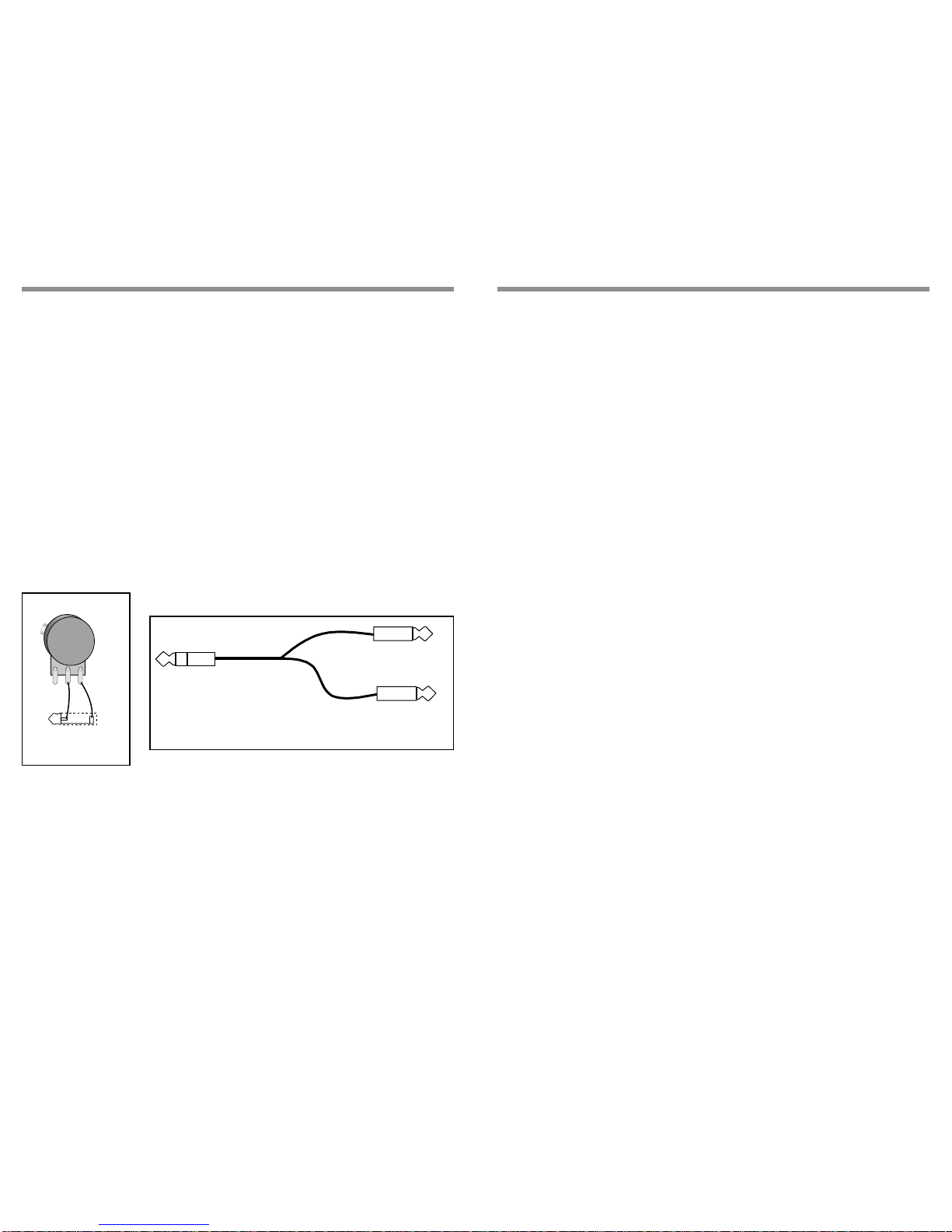
manuals.online logo
Brands
  1. Home
  2. •
  3. Brands
  4. •
  5. Rolls
  6. •
  7. Music Mixer
  8. •
  9. Rolls rm67 Installation instructions

Rolls rm67 Installation instructions

RM67
Mic/Source Mixer
OWNERS MANUAL
LIMITED WARRANTY
This product is warranted to the original consumer purchaser to be free
from defects in materials and workmanship under normal installation, use and
service for a period of one (1) year from the date of purchase as shown on the
purchaser’s receipt.
The obligation of Rolls Corporation under this warranty shall be limited
to repair or replacement (at our option), during the warranty period of any part
which proves defective in material or workmanship under normal installation,
use and service, provided the product is returned to Rolls Corporation, TRANS-
PORTATION CHARGES PREPAID. Products returned to us or to an authorized
Service Center must be accompanied by a copy of the purchase receipt. In the
absence of such purchase receipt, the warranty period shall be one (1) year from
the date of manufacture.
This warranty shall be invalid if the product is damaged as a result of
defacement, misuse, abuse, neglect, accident, destruction or alteration of the
serial number, improper electrical voltages or currents, repair, alteration or
maintenance by any person or party other than our own service facility or an
authorized Service Center, or any use violative of instructions furnished by us.
This one-year warranty is in lieu of all expressed warranties, obligations
or liabilities. ANY IMPLIED WARRANTIES, OBLIGATIONS, OR LIABILI-
TIES, INCLUDING BUT NOT LIMITED TO THE IMPLIED WARRANTIES
OF MERCHANTABILITY AND FITNESS FOR A PARTICULAR PURPOSE,
SHALL BE LIMITED IN DURATION TO THE ONE YEAR DURATION OF
THIS WRITTEN LIMITED WARRANTY. Some states do not allow limitations
on how long an implied warranty lasts, so the above limitation may not apply to
you. IN NO EVENT SHALL WE BE LIABLE FOR ANY SPECIAL, INCI-
DENTAL OR CONSEQUENTIAL DAMAGES FOR BREACH OF THIS OR
ANY OTHER WARRANTY, EXPRESSED OR IMPLIED, WHATSOEVER.
Some states do not allow the exclusion or limitation of special, incidental or
consequential damages so the above limitation or exclusion may not apply to
you. This warranty gives you specific legal rights, and you may also have other
rights which vary from state to state.
ROLLS CORPORATION
SALT LAKE CITY, UTAH
4/01
FEATURES
•Three XLR balanced inputs with phantom power
•Tone controls for each Mic input
• Clip indicators on all Microphone inputs
• Four stereo Source inputs
• 1/4” input for remote volume control
• RCA Record Out
• 1/4”TRS balanced outputs
INTRODUCTION
Thank your for your purchase of the Rolls RM67 Mic/Source Mixer.The RM67 is a
single rack space audio mixer with three XLR inputs and four stereo RCA source
inputs.Talkover features have been included on Mic 1 and Source 4 for paging
and music priority functions.
INSPECTION
1.Unpack and inspect the RM67 box and package.
If obvious physical damage is noticed, contact the carrier immediately to make a
damage claim.We suggest saving the shipping carton and packing materials for
safely transporting the unit in the future.
2.Please complete the Warranty Registration Card and return it to the factory.
APPLICATIONS
The RM67 is intended for mixing up to three microphones with up to four stereo
source signals.Applications include aerobics studios, karoake lounges, clubs and
restaurants, or audio visual applications. Its versatile inputs and outputs make it
an important problems solver in many audio situations.
TABLE OF CONTENTS
Introduction 1
Inspection 1
Applications 1
Table of Contents 1
Description 2
Connection 3
Operation 4
Specifications 5
Schematic 6
Warranty Back Cover
SCHEMATIC
1
ROLLS CORPORATION
1
E
Title: RM67 MIC/SOURCE MIXER
Size:
Rb Document Number:
RM67.SCH
Date: 12 - Mar - 2001
Rev:
Sheet of
+12V
+12V
LEVEL
-12V
-12V
+12V
-12V
RIGHT IN
LEFT IN
FX INSERT
+12V
-12V
RIGHT IN
LEFT IN
+12V
-12V
RIGHT IN
LEFT IN
+12V
-12V
+12V LEVEL
-12V
+12V LEVEL
-12V
-12V
PHAN PWR
PHAN PWR
PHAN PWR
+12V
+12V
+12V
-12V
SOURCE 4
RECORD OUT
+12V
D1
1N4001
D2
1N4001
P1
P100K
I
1
G
2
O3
U15
7812
I
2
G1
O3
U16
7912
R107
22K
R106
330
R108
22K R109
4.7K
R207
22K
P2
P100K
R208
22K R209
4.7K
R307
22K
R308
22K R309
4.7K P3
P100K
13
2
P5A
P100K X2
46
5
P5B
P100K X2
1
3
J5A
RCAX4
2
7
J5B
RCAX4
4
6
J5C
RCAX4
13
2
P6A
P100K X2
46
5
P6B
P100K X2
4
6
J6C
RCAX4
13
2
P8A
P100K X2
46
5
P8B
P100K X2
R602
47K
R605
47K
2
7
J6B
1
3
J6A
J7
PHONE 1/4
R117
100
1 3
2
P4A
P100K X2
4 6
5
P4B
P100K X2
R703
22K
R701
22K
5
8
J6D
RCAX4 R817
100
D3
1N4001
D4
1N4001
C10
1UF
1 2
3
J1
XLR F PC
1 2
3
J2
XLR F PC
1 2
3
J3
XLR F PC
5
8
J5D
RCAX4
C7
503
C12
503 C13
503 C14
503 C15
503
R101
4.99K
R201
4.99K
R301
4.99K
R401
10K
R403
10K
R501
10K
R504
10K
R601
10K
R604
10K
C105
27PF
C205
27PF
C305
27PF
C701
27PF
C702
27PF
R24
4.7K
C11
10UF
R505
47K
R502
47K
R702
47K
R704
47K
6
57
8
U1B
4560
2
31
4
U1A
4560
2
31
4
U2A
4560
6
57
8
U2B
4560
6
57
8
U3B
4560 2
31
4
U3A
4560
2
3
1
4
U8A
4560
5
6
7
8
U8B
4560
2
31
4
U9A
4560
6
57
8
U9B
4560
6
57
8
U5B
4560
2
31
4
U5A
4560
6
57
8
U4B
4560
2
31
4
U4A
4560
C601
27PF
C602 27PF
2
31
4
U7A
4560
C501 27PF
C502 27PF
C402
27PF
C401 27PF
C104 27PF
C30427PF
C101
10U
C201
10U
C301
10U
R116
100K
D5
R404
47K
R402
47K
R103
22K R105
330
C103
.001
12
3SW2A
DPDT
R102
4.99K
C102
10U 45
6SW2B
DPDT
R104
22K D102
1N4148
D101
1N4148
R114
100K
R115
10K
Q1
2N3904
D6
LDRR
D7
LDRR
Q2
2N3904
R215
10K
R214
100K
D202
1N4148
D201
1N4148
D302
1N4148
D301
1N4148
R314
100K
R315
10K
Q3
2N3904
D8
LDRR
R203
22K
12
3SW3A
DPDT R205
330
C203
.001
R206
330
45
6SW3B
DPDT
C202
10U
R202
4.99K R204
22K
R303
22K
12
3SW4A
DPDT R305
330
C303
.001
R306
330
R304
22K
C302
10U
R302
4.99K
45
6
SW4B
DPDT
R807
100
R808 47K
2
31
4
U10A
4560
R818
47K
6
57
8
U10B
4560
R313
4.7K
R213
10K
R113
4.7K
C9
1000UF
C8
1000UF
BASS
TREBLE
RIGHT
BASS
TREBLE
LEFT
MONO
DUCK
+12V
+12V
-12V
-12V
13
2
P10A
P100K X2
46
5
P10B
P100K X2
13
2
P11A
P100K X2
46
5
P11B
P100K X2
6
57
8
U11B
4560
2
31
4
U14A
4560
6
57
8
U14B
4560
2
31
4
U11A
4560
J11
J10
PHONE 1/4
R901 10K
R902
33K
R903
330K
C902
27PF
2
31
4
U6A
LM358
D13
1N4148
C901
.1
R904
330K
112
SW1A
SW DIP-6
R809
33K
R810
22K
R811
33K
R813
33K
R814
1M
R815
10K
R816
10K
211
SW1B
SW DIP-6
R14
22K
R1
22K
R9 51
R10
51
R827
1M
R16
47K
R819
33K
R820
22K
R821
33K
R824
1M
R823
33K
R825
10K
R826
10K
R22
51
R23
51
R905
100K
C2
27PF C3
10U
C5
27PF
C6
10U
C903
10U
C806
220PF
C808
220PF
C807
.047
C805 .047
R8 47K
R21 47K
Q5 J113
Q6
J113
D12
1N4148
D11
1N4148
-12V
Q4
2N3906
D14
1N4148
C904
10U
+12V
+12V
+12V
+12V
14
13 9
16
6
12
10
15
U13B LM13600
3
48
111
5
7
2
U13A
LM13600
R19
200
R5
200
R12 33K R11
4.7K
R20
47K
R6
47K
R7
10K
R13
10K
Q7
2N3906
R812
33K
R82233K
3SW1C
SW DIP-6
4 9
SW1D
SW DIP-6
5 8
SW1E
SW DIP-6
+12V
+12V
+12V Q9
J113
Q10
J113
CR1
1N4148
CR2
1N4148
DUCK
R801
33K R802330K
C802
27PF
6
57
8
U6B
LM358 D10
1N4148
C25
.1
R805
330K
6 7
SW1F
SW DIP-6
R806
100K
C803
10U
D9
1N4148 C804
10U
R803
1M
R804
47K
-12V
C801
503
+12V
+12V
-12V
R606
47K
R603
47K
2N3904
R503
47K
R506
47K
C809
503
2
31
4
U12A
4560
6
57
8
U12B
4560
R3
100K
R17
100K
R2
22K
R15
22K
C1
27PF
C4
27PF
1
2
3
J8
PCRCAX2
R18
1K
R4
1K
-12V
R111
4.7K R112
100K
R211
4.7K R212
100K
R311
4.7K
R312
100K
R110
4.7K
R210
4.7K
R3104.7K
P7
P100K
P12
P100K
P13
P100K
C106
.1
C206
.1
C306
.1
C107
.01
C207
.01
C307
.01
J4
PHONE 1/4
6
57
8
U7B
4560
C204
27PF
-12V
+12V
-12V
+12V +12V -12V -12V
E1 WIREPAD
E2 WIREPAD
E3
WIREPAD
+12V
+12V
CR? 1N751A
PHONE 1/4
LEVEL
Q8
POWER
5968 South 350 West
Salt Lake City, UT 84107
1 6
DESCRIPTION
FRONT PANEL
Mic 1 - 3:Adjust the level of signal from the corresponding Mic Input.
CLIP LED:Indicates overload in the channel.The LED lights 3dB below clipping.
TONE 1 - 3: Adjusts the frequency content of the signal in the channel.Turning
this control clockwise increases the higher frequencies orTreble portion of the
signal, turning the control counterclockwise increases the Bass portion.
Source 1 - 4:Adjust the volume of input from the RCA Source Inputs.
Bass:Adjusts the low frequencies of the Source signals only.
Treble:Adjusts the high frequencies of the Source signals only.
PWR:LED indicating power is applied to the RM67 and the unit is on.
REAR PANEL
MIC
3MIC
2MIC
1
MIC/LINE
MIC
INSERT
MAIN
OUTPUTS
LEFT RIGHT
WARNING:
DO NOT EXPOSETHIS EQUIPMENT TO RAIN OR MOISTURE.
120VAC
50/60 Hz 15 VA
MODEL RM67
MADE IN U.S.A.
SERIAL NUMBER
67-
RISQUE DE CHOC - NE PAS ENLEVER
NRTL /C
MIC/LINE MIC/LINE
1234
M
O
N
12
S
T
RECORD
OUT
REMOTE
VOLUME
SOURCE INPUTS
T.O. PHAN
321
Mic 1 - 3:XLR inputs for dynamic or condenser microphones, or balanced line-
level signals.
Mic/Line Switch:Pads the XLR Mic input by 30 dB when in.
DIP SWITCH:Contains the jumpers for engaging Mic 1 - 3 phantom power, the
talkover functions, and the Mono/Stereo select.
MIC INSERT:1/4”TRS insert jack for adding external processing to the Mic
signals.Tip = send, ring = return.
SOURCE INPUTS:Stereo RCA jacks, Channels 1 - 4, for connection to stereo
sources such as AM/FM tuners, cassette players, cd players, or video players.
RECORD OUT:Stereo RCA jacks, contains all mixed signals before the Remote
Volumejack.
REMOTE VOLUME:1/4”TS jack for connection to a remote potentiometer for
master volume control.20K Ohm audio taper potentiometer is recommended.
MAIN OUTPUTS:1/4”TRS balanced Right and Left Outputs.
SPECIFICATIONS
Input Impedance: Mic: 600 9XLR balanced
Line: 22K 9
Source:
22K
9
gold plated RCA
Mic Insert: 22K 91/4" TS unbal.
Max Input Level: Mic: -14 dBV Mic level
+20 dB Line levl
Source: 24 dBV
In/Out Connectors: 3: XLR, 4: Stereo RCA, 3: 1/4"TRS, 1: 1/4”TS
Phantom Power: +12 VDC
Output Level: +17 dBV max
Output Impedance: 51 9
Max Gain: Mic: 60 dB
Source: 26 dB
Tone Controls: +/-12 dB 100 Hz Bass
+/-12 dB 11kHz Treble
Nose Floor: - 80 dB, THD: <.025%, S/N Ratio: 96 dB
Size: 19" x 1.75" x 6" (48.3 x 4.5 x 15 cm)
Weight: 5 lbs. (2.3 kg)
25
Tip Sleeve
20KΩAudio Taper
Connects to tip
SEND
Connects to ring
RETURN
To Mic Insert
Fig. 2
Fig. 1
OPERATION
After proper microphone, source, insert and remote volume control connections
have been made, connect the RM67 to a properly grounded AC outlet.
DIP SWITCH SETTINGS
•If a microphone requires phantom power, move the Mic channel’s corresponding
PHAN DIP switch to the down position.This applies 12 volts dc phantom power to
the indicated microphone.
•Talkover switch 1 (T.O. 1), when in the down position, all program material on all
Source inputs will be “ducked”or muted when a signal is present at Mic 1.
This function is used for paging.When a person talks into Mic 1, and the Talkover
1 switch is on (down), all source signals will be muted.
•Talkover switch 2 (T.O.2), when in the down position, Source 1,2, and 3 will be
“ducked”or muted by the signals at Source 4.
This function is for jukebox priority.With a jukebox connected to Source input 4,
and theTalkover switch 2 on (down), the other Source input signals such as
background music, will be muted and only the jukebox will be heard.
•The Mono/Stereo switch selects the output mode.When the switch is down, the
unit is in stereo mode.When the switch is up, the stereo signals are mixed to
mono and sent to both the Right and Left Main output jacks.Either jack can be
used as a mono output.
Move the power switch to the on position - so the red portion of the switch is
showing to apply power to the RM67.
Adjust the Microphone levels for maximum input signal without clipping, and for a
comfortable listening level.Adjust each Source level for a desired listening level.
CONNECTION
Connect low impedance microphones to the Mic inputs. If a paging microphone is
being used, connect it to Mic Input 1.Connect source signals such as CD players,
cassette players or video players to the RCA Source Inputs.
RemoteVolume Control
To control the overall output volume of the RM67 in a remote location, a 20K ohm
audio taper potentiometer should be wired to a 1/4”tip-sleeve plug and connected
to the RemoteVolume jack.Shown below in Fig.1 is a wiring example for the
remote volume control.
Mic Insert
To connect a signal processor to the RM67 microphone signal(s), use an insert
plug, or cable wired as shown above in Fig.2.
Connect the Main Right and Left outputs to the power amplifiers.The RM67
output jacks will accommodate balanced or unbalanced connections. For unbal-
anced operation use 1/4”Tip Sleeve jacks, for balanced operation use 1/4”Tip
Ring Sleeve jacks.If a 1/4”TRS to XLR cable is needed, wire theTip of the 1/4”
jack to pin 2 of the XLR, the Ring to pin 3, and the Sleeve to pin 1 or the shield.
3 4

Other Rolls Music Mixer manuals

Rolls RM64 User manual

Rolls

Rolls RM64 User manual

Rolls RM64OLD User manual

Rolls

Rolls RM64OLD User manual

Rolls RM64 User manual

Rolls

Rolls RM64 User manual

Rolls Field Mixer MX442 User manual

Rolls

Rolls Field Mixer MX442 User manual

Rolls RM67 User manual

Rolls

Rolls RM67 User manual

Rolls MX51S User manual

Rolls

Rolls MX51S User manual

Rolls MX54s User manual

Rolls

Rolls MX54s User manual

Rolls MX56c User manual

Rolls

Rolls MX56c User manual

Rolls RM83T User manual

Rolls

Rolls RM83T User manual

Rolls RM74 User manual

Rolls

Rolls RM74 User manual

Rolls RM69 MixMate 3 User manual

Rolls

Rolls RM69 MixMate 3 User manual

Rolls RM65 MIXMAX6 User manual

Rolls

Rolls RM65 MIXMAX6 User manual

Rolls RM82 User manual

Rolls

Rolls RM82 User manual

Rolls RM65 HEXMIX User manual

Rolls

Rolls RM65 HEXMIX User manual

Rolls MX34c LiveMix User manual

Rolls

Rolls MX34c LiveMix User manual

Rolls MX310 MorMic User manual

Rolls

Rolls MX310 MorMic User manual

Rolls MX41s User manual

Rolls

Rolls MX41s User manual

Rolls MX122 User manual

Rolls

Rolls MX122 User manual

Rolls PROMIX IV MX124 User manual

Rolls

Rolls PROMIX IV MX124 User manual

Rolls MiniMix VI MX28 User manual

Rolls

Rolls MiniMix VI MX28 User manual

Rolls MX124 User manual

Rolls

Rolls MX124 User manual

Rolls MX153 Mix Mate User manual

Rolls

Rolls MX153 Mix Mate User manual

Rolls RM67 User manual

Rolls

Rolls RM67 User manual

Rolls RM64 User manual

Rolls

Rolls RM64 User manual

Popular Music Mixer manuals by other brands

Avizia CA750 User and installation manual

Avizia

Avizia CA750 User and installation manual

Yamaha EM-1620 Operation manual

Yamaha

Yamaha EM-1620 Operation manual

DAPAudio Oxygen owner's manual

DAPAudio

DAPAudio Oxygen owner's manual

Sony FXE-120 Specifications

Sony

Sony FXE-120 Specifications

Yamaha MG82CX owner's manual

Yamaha

Yamaha MG82CX owner's manual

Mackie 402VLZ4 Specifications

Mackie

Mackie 402VLZ4 Specifications

Samson XM 410 specification

Samson

Samson XM 410 specification

Yamaha MG10/2 Service manual

Yamaha

Yamaha MG10/2 Service manual

RDL RU-MX5 installation instructions

RDL

RDL RU-MX5 installation instructions

Sound Devices 664 User guide and technical information

Sound Devices

Sound Devices 664 User guide and technical information

Omnitronic PM-444USB user manual

Omnitronic

Omnitronic PM-444USB user manual

Powerwerks PW6EFX owner's manual

Powerwerks

Powerwerks PW6EFX owner's manual

Samson Txm16 owner's manual

Samson

Samson Txm16 owner's manual

AMT EgoGig EG-4 user guide

AMT

AMT EgoGig EG-4 user guide

Ross RAVE manual

Ross

Ross RAVE manual

Shure FP33 Operation guide

Shure

Shure FP33 Operation guide

Alto-Shaam ZMX122FX quick start guide

Alto-Shaam

Alto-Shaam ZMX122FX quick start guide

PRESONUS StudioLive 24R Networking guide

PRESONUS

PRESONUS StudioLive 24R Networking guide

manuals.online logo
manuals.online logoBrands
  • About & Mission
  • Contact us
  • Privacy Policy
  • Terms and Conditions

Copyright 2025 Manuals.Online. All Rights Reserved.