Rolls S48-100LFP ESS User manual

ROLLS S48-100LFP ESS
BATTERY OPERATING
MANUAL
Recommended safety, installation, operating,
and troubleshooting procedures for Rolls
S48-100LFP (Lithium Iron Phosphate) ESS
(Energy Storage Systems).

BACKUP
SYSTEMS
RENEWABLE
ENERGY

1
TABLE OF CONTENTS
02 Rolls S-Series 48V LFP ESS (Energy Storage Systems)
04 Version History/Changelog
04 Product Description Installation
05 Cable Connections, Terminal Torque, Single Battery Installation, Parallel Battery Installation
06 Without Combiner Box
07 With Combiner Box
09 Battery Operation, First Start, LED Indicator Instructions
11 LCD Screen, BMS Protection Summary
11 Battery Charging
12 Charging Guidelines
13 Charging Source: Lead-Acid Battery Charger
13 1-Stage Charging – CC (Constant Current)
14 2-Stage Charging – CC/CV
15 3-Stage Charging - Legacy Lead-Acid Systems, Inverter/Charger Hardware
16 Charging Temperature
17 Communication Interface, CAN Communication, RS-485 Communication
18 Parallel Communication, BMS Storage Function
19 Parallel Pack Selector Switch 4-Dip, Troubleshooting
20 Storage, Recycling, LFP Glossary
22 Appendix
24 Contacts

23
ROLLS S48-100LFP ESS
Rolls S-Series 48-volt Lithium Iron Phosphate (LFP/LiFePO4) Energy Storage System
(ESS) batteries are designed for use in larger-scale, 48V (51.2V nominal) systems, for
grid-connected backup and off-grid purposes. Rolls S-Series 48V LFP ESS batteries are
designed to scale in parallel capacity only at this voltage level, with communication
between batteries and to externally connected equipment.
This manual provides detailed instructions for safe and proper installation, operation, and
care specifically of Rolls S-Series 48V LFP ESS batteries. Please read carefully to clearly
understand the operating instructions and any potential safety risks prior to installation.
Failure to install or use this battery as instructed may result in damage to the product that
may not be covered under the manufacturer warranty. See warranty terms & conditions for
full details.
NOTE: This manual offers installation, charging and troubleshooting guidance for Rolls
S-Series 48V LFP ESS battery only.
See Rolls S24-2800LFP & S48-6650LFP ESS Battery Operating Manual for usage instructions
specific to Rolls S24-2800LFP ESS and S48-6650LFP ESS (Energy Storage System) models.
See Rolls R-Series & S-Series Drop-in LFP Battery Operating Manual (Grey and Red plastic
cases, BCI sizes) manual for usage instructions specific to Rolls R-Series & S-Series drop-in
LFP models.
Para ver la versión en español, haga clic aquí.
O consulte nuestro sitio web.
This document is NOT APPLICABLE to the following models
S-Series 12V & 24V LFP R-Series 12V & 24V LFP 24V & 48V ESS LFP Models
(S48-6650LFP ESS &
S24-2800LFP ESS)
(R12-___LFP & R12-___LFP)(S12-___LFP & S24-___LFP)

23
LFP Battery Lead-Acid Battery
Cell Voltage = 3.2V Cell Voltage = 2.0V
Battery Nominal Voltage
51.2V (16 cells)
Battery Nominal Voltage
48V (24 cells)
Nominal voltage of an LFP battery differs from equivalent lead-acid batteries.
WARNING: Explosion, Electrocution, Or Fire Hazard
• A battery can present a risk of electric shock, burns from high short circuit current, fire,
or explosion.
• Ensure cables are properly sized for the system current and cable runs are as short as
possible, reducing line inductance and voltage spikes, which can damage the BMS.
• Ensure adequate airflow around batteries and that they are clear of debris.
• Never smoke or allow a spark or flame near the batteries.
• Always use insulated tools.
• Avoid dropping tools onto batteries or other exposed electrical parts.
• Cold temperatures can be especially damaging to batteries after even a single low
temperature event.
• Never charge a Rolls S-Series 48V LFP ESS battery below 0°C (32°F).
• Never discharge a Rolls S-Series 48V LFP ESS battery below -20°C (-4°F).
• Never charge a battery with a deformed or bulging case.
• Do not expose a Rolls S-Series 48V LFP ESS batteries to heat more than 60°C (140°F)
during operation, and do not store for extended periods of time above 45°C (113°F). Do not
incinerate or expose to open flames.
• If a battery must be decommissioned/removed, always open the breaker first, then remove
the grounded terminal from the battery. Make sure all devices are disconnected.
• When installing, leave adequate clearance between batteries consistent with local code
requirements and or Rolls racking systems.
• When replacing batteries, use the same make, model & quantity of batteries.
• Do not mix old and new batteries.
• Avoid any fall or collision during the installation process.
• Do not dismantle or remove the battery components.
• Battery maintenance should be carried out by qualified personnel.

45
Rev. Changelog Author/Editor Date
1.0 Release Version Jordan Torrealba 2023/08/15
VERSION HISTORY/CHANGELOG
PRODUCT DESCRIPTION
Rolls S-Series 48V LFP ESS batteries are 19” rack-mount and wall-mount compatible.
These batteries are intended for large-scale, higher capacity installations than our drop-in
replacement lines.
Cabinets installation instruction are available online at: Rolls S-Series LFP ESS Cabinet
Assembly Manual.
For Rolls S-Series 48V LFP ESS batteries with connectable PC software, the manual is
available online at: Rolls LFP Desktop Manual.
PANEL FEATURES
INSTALLATION
This section describes installation steps and considerations for your Rolls S48-100LFP ESS
product. The battery pack can be installed horizontally or vertically.
NOTE: Only trained electrical power system technicians should install the device. Before
installing or removing the battery, make sure that the system is disconnected from any
power source and that the battery device is turned off. Distribution cabling needs to be
handled carefully with reasonable protective measures to avoid being touched during the
maintenance and operation.
1. Positive Terminal (2*M6)
2. SOC LED
3. RUN Indication
4. Fault Indication
5. Parallel Address DIP
6. CAN bus Communication
7. RS-485 Communication
8. RESET Switch
9. LCD Display & Navigation
10. On/Off Breaker
11. Protection Breaker
12. Negative Terminal (2*M6)

45
CABLE CONNECTION
All cable connections should be adequately sized, insulated, and undamaged. The cable
connectors should be clean and properly mated with the battery terminals to ensure a snug
connection. Terminal connections should be torqued to the recommended specification
below. Although Rolls S-Series LFP ESS batteries do not require maintenance, routine
inspection of cabling and terminal connections is recommended.
Amperage 25 30 40 55 75 95 130 150 170 195 260
Wire Gage 14 12 10 8 6 4 2 1 1/0 2/0 4/0
TERMINAL TORQUE
Rolls batteries using M6 fasteners should be torqued to 8-10Nm.
DO NOT OVERTORQUE: If a terminal is damaged, do not attempt to repair the terminal. Do
not use the battery if the recommended torque specification cannot be met.
SINGLE BATTERY INSTALLATION
Rolls S-Series ESS rack-mount batteries are compatible with standard 19” rack hardware.
For single battery installation, connect the positive and negative terminal of the battery
pack to the positive and negative terminal of the system bus with the appropriately sized
red and black cable, respectively. If you intend to use a combiner box, directly connect the
positive and negative terminals of the battery pack to the combiner box terminals.
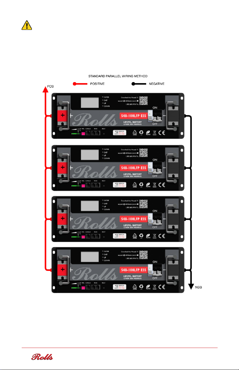
PARALLEL BATTERY INSTALLATION
Rolls S-Series ESS rack-mount batteries are compatible with standard 19” rack hardware.
Rolls S-Series ESS batteries can be combined in parallel to increase system capacity and
power delivery. Rolls S-Series S48-100LFP ESS can support up to 16 battery packs in parallel
and is certified to UL 1973. Parallel batteries can be installed in the modular Rolls LFP ESS
cabinet, and expandable up to 32U per cabinet (i.e., Eight S48-100LFP ESS batteries can be
configured in a single rack).
The standard cabinet comes with a high current combiner box to connect the positive
and negative terminals from the battery to the outlet terminal at the top of the cabinet.
Refer to the connection diagram below and use appropriate cable sizing and length during
installation. The length, thickness, material, and resistance of all the cables connected in
parallel must be the same.
NOTE: Refer to the Communication Interface section for the parallel communication
cable connections.
NOTE: Undersized cables may lead to cable and/or battery damage, charging issues,
terminal heating, or fire.

67
WARNING: Series connection of 48V S-Series LFP ESS batteries is not supported.
Connecting batteries in series will directly lead to BMS failure under numerous
conditions, risking cell health, user safety, and will void the product warranty.
WITHOUT COMBINER BOX

67
WITH COMBINER BOX

89
BATTERY OPERATION
FIRST START: When you have verified the connections, terminal torque, and external
connections are made, batteries can be activated. For batteries with a breaker, this can be
closed, which will electrically connect the terminals to the battery. The change in external
voltage or load application will wake the BMS.
If the BMS does not wake immediately, press the RESET button located beside the
display to wake the BMS from sleep mode.
LED INDICATOR INSTRUCTIONS
SOC
STATE CHARGE DISCHARGE
ALARM RUN
Rolls S-Series 48V LFP ESS batteries have four capacity indicator lights to display the
current state-of-charge estimate and charging status, one alarm light for error indication,
and one run light. This configuration is consistent across each LFP ESS model.
When the battery is charging, the RUN light will be on. When the battery is discharging, the
RUN light will be flashing.
Run Light ON Flashing
STATE CHARGE DISCHARGE
Capacity
Indicator
75-100%
50-75%
25-50%
0-25%

89
LCD SCREEN
Use of the LCD screen is consistent with the on-screen instructions and provides quick and
effective access to voltage, temperature, current, SOC, and fault information.
BMS PROTECTION SUMMARY
Rolls S-Series 48V LFP ESS batteries include a built-in battery management system (BMS)
which offers protection in conditions where the battery voltage, current, and switch or cell
temperature may be unsafe or damaging. The BMS in S-Series 48V LFP ESS models provides
protection against cell and pack overvoltage and undervoltage, charge and discharge
overcurrent, high and low temperature, and short circuit. The switch architecture of the
BMS allows charge and discharge to be stopped independently. Under these undesirable
operating conditions, the internal BMS will interrupt the current into or out of the battery
independently, or disconnect it fully, as required.
For S-Series 48V LFP ESS batteries with secondary protection and UL 1973 certification, in
the event of a failure that cannot be managed by the BMS, the secondary protection device,
either a contactor or shunt-trip breaker, will be opened to disconnect the battery from the
external electrical system.
Rolls S-Series 48V LFP ESS batteries without a secondary current-path breaker may include
an external BMS switch. This will be noted on the datasheet for the specific model. The
external BMS switch is not on the main current path but can be used to disconnect the
battery from the terminals via the BMS. This is an effective way to reduce terminal arcing
on initial connection.
The BMS on all S-Series 48V LFP ESS batteries also incorporates RS-485 and CANBUS
communication ports. Data communication among connected batteries is carried out
through RS-485 communication. The same bus can be connected to a computer for
parameter configuration and data monitoring using the Rolls LFP Desktop PC software.
Refer to the Communication Interface and Rolls LFP Desktop Manual for connection
instructions to your PC.

10 11
BATTERY
LIMIT PROTECTION RESET METHOD COMMENTS
Cell/Pack
Overvoltage
Charge
Interruption
1. The cell voltage drops to
the overvoltage recovery
point (3.4V).
2. When the remaining
capacity is lower than
96% of the intermittent
charging capacity or
discharge current >1A.
If occurring more than
3 times in 2 minutes,
discharge is required.
Cell/Pack
Undervoltage
Discharge
Interruption
Shut down after
undervoltage
protection and
maintain communication
for 1 minute.
Charging current detected
(>1A).
If occurring more than
3 times in 2 minutes,
charge is required.
Extended Pack
Undervoltage
(Stored While
Empty)
Battery Cannot
be Recovered
Always charge S-Series ESS
LFP Batteries within 72 hours
of full discharge.
_
Pack Overcurrent
or Short Circuit
Charge and
Discharge
Interruption
Automatically reset after
time delay.
If occurring more than
3 times in 2 minutes,
charge is required.
High temperature
at BMS or Cell*
Charge and
Discharge
Interruption
Automatically reset after
cooling.
BMS will display alarm
when approaching
disconnect.
Low temperature
at BMS or Cell*
Charge
Interruption
Automatically reset after
warming.
BMS will display alarm
when approaching
disconnect.
Extreme low
temperature at
BMS or Cell
Charge and
Discharge
Interruption
Automatically reset after
warming.
BMS will display alarm
when approaching
disconnect.
*Temperatures outside of the ideal operating range require a reduction in charge/discharge
current for optimal battery life.
NOTE: Cells are balanced internally, some S-Series LFP ESS models have provisions for the
addition of active balancers.

10 11
BATTERY CHARGING
Although a lithium-specific charger is recommended, Rolls S-Series ESS LFP models
are compatible with most common lead-acid battery chargers for nominal voltage of the
pack. Programming should adhere to the LFP charging requirements, noting the
recommended and maximum charge and discharge rates. These are specified on the
product label and datasheet.
Rolls S-Series LFP ESS batteries may cycle or be stored in a partial state-of-charge
(PSOC). Rolls S-Series LFP ESS batteries should be cycled from 0% depth of
discharge (DOD) or 100% state of charge (SOC), to 80% DOD or 20% SOC for optimal
cycle life. To prevent over-discharge, the BMS will disconnect the battery when the low
voltage cut-off is reached, protecting the battery from over-discharge.
NOTE: The reset button can be used if chargers that require the detection of voltage at
the battery terminals for use fail to wake battery from a state of under-voltage
protection.
NOTE: LFP cells do not need maintenance charges like equalization, pulse charge,
overcharge, or any others typically recommended or required for lead-acid batteries.
NOTE: The recommended and maximum continuous charge and discharge rates are
specific to each S-Series 48V LFP ESS model by cell and BMS technology. This is
specified on the product label.

12 13
CHARGING GUIDELINES
Rolls S-Series 48V LFP ESS batteries may be charged in a 1, 2, or 3-stage charge
profile, shown below. The specifics and recommended setpoints for these charge
regimes are explained in this section, with the recommended charge profile
being a 2-stage charge.
Representation of recommended 2-stage Constant Current/Constant Voltage (CC/CV)
charging. The dotted line represents the transition from CC to CV when the voltage limit
is reached. Once the battery reaches the constant voltage limit, the battery is held by
the charger at this voltage until the current decreases to 0.05C. At this point the battery
is at 100% state-of-charge (SOC). Any current continuing to flow in the float stage is
attributable to balancing activity of the BMS.
Representation of 1, 2, and 3-Stage Charging Profiles
VOLTAGE CURRENT
1-STAGE
2-STAGE
3-STAGE

12 13
NOTE: 1-Stage CC Charging may be required if charging from a source which is not
efficient to run at lower power. However, it may only charge the battery to 90-95% SOC.
1-Stage charging also offers very little time to balance cells. For these reasons, 2-Stage
CC/CV charging is recommended to ensure the battery reaches full SOC.
CHARGING SOURCE: LEAD-ACID BATTERY
CHARGER
Customers may choose to replace lead-acid batteries with lithium models. Most leadacid
battery chargers may be used to charge Rolls LFP batteries if the charger is
properly configured to operate within recommended charge current and voltage limits.
The pre-programmed voltage settings for AGM or OPzV GEL models may be in line
with LFP charge voltage settings and can sometimes be used if direct voltage control is
not possible for your charger. However, flooded lead-acid batteries often require higher
charge voltage settings. If left configured for charging flooded batteries, the higher
charge voltage can trigger the BMS to restrict charging to protect the battery, effectively
resulting in a 1-stage charge. If this occurs repeatedly, or the charger cannot be
configured at a lower charge voltage, it may be necessary to replace the charger.
1-STAGE CHARGING – CC (CONSTANT CURRENT)
When charging with a single-stage constant current charger, charge at the
recommended charge current until the battery reaches its termination voltage.
Recommended Charging Current for Optimal Life
Maximum Continuous Charging Current
S-Series
1-STAGE CHARGE PROFILE
Temperature Range
0-10°C (32-50°F)
10-35°C (50-95°F)
35-55°C (95-131°F)
Optimal Current
≤ 0.2C
≤ 0.5C
≤ 0.2C
0.5C
SYSTEM 24V NOMINAL 48V NOMINAL
TERMINATION VOLTAGE 28.8V 57.6V

14 15
2-STAGE CHARGING – CC/CV
When charging with a two-stage constant current/constant voltage (CC/CV) charger,
charge at the recommended charge current, by operating temperature, until the battery
reaches the “absorption” voltage or constant voltage (CV) limit. The charger then holds
the battery at CV until the charge current decreases to ≤0.05C (termination current).
The recommended absorption (constant voltage) voltage is shown below. If the charger
has a pre-set voltage setting or cannot be programmed, an absorption voltage in the
range below is also acceptable. Note: lower voltage will lead to longer charge times.
NOTE: If charge time is not a concern within your system architecture, reducing the
absorption voltage will increase charge time, but allows the BMS more time to ensure all
cells remain balanced. As batteries age, small changes in manufacturing or due to
uneven wear may present themselves, requiring more time to maintain balance.
Recommended Charging Current for Optimal Life
Maximum Continuous Charging Current
S-Series ESS
2-STAGE CHARGE PROFILE
Temperature Range
0-10°C (32-50°F)
10-35°C (50-95°F)
35-55°C (95-131°F)
Optimal Current
≤ 0.2C
≤ 0.5C
≤ 0.2C
0.5C
SYSTEM 24V NOMINAL 48V NOMINAL
RECOMMENDED ABSORPTION
VOLTAGE
ABSORPTION RANGE
(ACCEPTABLE)
TERMINATION CURRENT
28.8V
28.0V - 29.2V
≤0.05C
57.6V
56.0V - 58.4V

14 15
3-STAGE CHARGING - LEGACY LEAD-ACID
SYSTEMS, INVERTER/CHARGER HARDWARE
When programming an inverter/charger or charge controller equipment using a 3-stage
charge sequence (2-stage with an additional “float voltage” after the charge is
terminated), the following charging parameters should be programmed to properly
charge Rolls S-Series ESS batteries:
Temperature Compensation: If the inverter/charger or charge controller uses temperature
compensation this should be turned off when charging Rolls R-Series and S-Series models.
Turn off the temperature compensation settings and disconnect the sensor to ensure the
correct voltage regulation from the charging device.
Equalization: Equalization should never be used; elevated charge voltages are
unacceptable for LFP batteries and will simply lead to the BMS disconnecting the charging
path. It should be turned off, or the equalization voltage setpoint should be reduced to the
appropriate system float voltage, above.
Some charger models may require additional firmware, programming, or parameters.
Please contact your inverter/charger or charge controller manufacturer for assistance with
these settings, if required.
Recommended Charging Current for Optimal Life
Maximum Continuous Charging Current
R-Series S-Series
3-STAGE CHARGE PROFILE
Temperature Range
0-10°C (32-50°F)
10-35°C (50-95°F)
35-55°C (95-131°F)
Optimal Current
≤ 0.2C
≤ 0.5C
≤ 0.2C
1C*0.5C
SYSTEM 24V NOMINAL 48V NOMINAL
BULK to ABS VOLTAGE
ABSORPTION VOLTAGE
ABS to FLOAT
FLOAT VOLTAGE
28.8V
28.8V
≤0.05C
27.2V
57.6V
57.6V
≤0.05C
54.4V

16 17
CHARGING TEMPERATURE
Due to the chemistry of Lithium-ion cells, these batteries cannot accept high charge current
at lower operating temperatures without risking cell damage and permanent loss of capacity.
Rolls S-Series ESS LFP batteries may be safely charged between 0°C to 55°C (32°F to 131°F).
However, because cycle wear is accelerated below 10°C (50 °F) the charge should be limited
to 0.2C (20% of battery capacity) for optimal longevity. Similarly, at high temperatures, charge
current should be limited to ≤0.2C when operating at temperatures from 35°C to 55°C (95°F to
131°F) as noted below.
To maintain optimum performance and durability of Rolls S-Series ESS LFP batteries, the
following charge current limits should be followed:
NOTE: Due to the internal chemistry, batteries can be discharged at lower temperatures
than they can be charged at. So, at low temperatures between -20°C and 0°C, batteries
can still be effective energy storage, if no energy is put into the batteries.
The recommended and maximum continuous charge current is specified for each Rolls
S-Series ESS LFP model as a function of capacity. This information is noted in the
product label and datasheet.
TEMPERATURE RECOMMENDED CHARGE CURRENT
0-10°C (32-50°F)
< 0°C (< 32°F)
10~35°C (50-95°F)
35~55°C (95-122°F)
> 55°C (> 122°F)
≤ 0.2C
DO NOT CHARGE
≤ 0.5C
≤ 0.2C
DO NOT CHARGE

16 17
COMMUNICATION INTERFACE
The BMS of the battery pack has one CAN bus communication port and two RS-485
communication ports for closed loop communication. Using closed loop communication
is not required. All inverters, when set with proper voltage and current setpoints for
charge and discharge, can be used with our batteries. A list of inverters which can take
advantage of closed loop communication can be found in Appendix A.
CAN COMMUNICATION
The CAN bus port pinout is below. See Appendix A for compatible inverters.
COMMUNICATION STANDARD BAUD RATE
CAN 500k Standard
PIN DESCRIPTION
1,8
2,7
3,6
4,5
RS-485-B
RS-485-A
Ground
NC
1 8
(Port)
PIN DESCRIPTION
1,2,7,8
4,5
3,6
NC
Can-L, Can-H
Ground
1 8
(Port)
COMMUNICATION STANDARD BAUD RATE
RS-485 19200
RS-485 COMMUNICATION
The RS-485 port pinout is below. See Appendix A for compatible inverters.
When connecting between batteries over RS-485, a standard network cable is used.

18 19
PARALLEL COMMUNICATION
When multiple batteries are connected in parallel, the RS-485 interface is used as the
parallel communication interface and host computer interface. The host computer can
read the sum of the battery data of all parallel packs through the RS-485 interface. An
example connection is shown in the figure below:
BMS STORAGE FUNCTION
BMS in the Rolls S-Series 48V ESS LFP batteries have built-in storage which provides
real-time storage of measurement data of various events such as alarms, protection
triggers. It can be stored by setting the record start time, record end time, and record
interval from the PC software settings. The BMS in the Rolls S-Series 48V ESS LFP
can store up to 100 historical data records, which can be read by the host computer and
saved as a spreadsheet.
Table of contents