Romet AdEM-PTZ User manual

A D V A N C E D E L E C T R O N I C M O D U L E
O P E R A T I N G M A N U A L
May 2019 Rev.13
P/N 17-MN-CA

TABLE OF CONTENTS
1. INTRODUCTION TO AdEM®-PTZ 1
Characteristic and What’s New 1
How to Specify Model 2
How it Works 2
RometLink Software 3
AdEM®-PTZ Typical Application 6
2. GETTING STARTED 7
Keyboard Operation 7
Scroll-button Operation 8
Scroll Magnetic Sensor 8
Operations Menu Structure 9
3. MODES OF OPERATION 10
Normal Display Mode 10
Custom Display Mode 10
Full Display Mode 11
Set Up Mode 11
Calibration Mode 11
Proving Mode 11
Testing Mode 11
Communication Mode 11
4. SECURITY 12
Password 12
Program Switch Jumper 13
How to Enable/Disable Program Switch 15
Event Logger Type A 16
5. SET UP 18
Set Up –Flowchart 19
Set Up by Software 25
6. CALIBRATION 29
Temperature Calibration 29
Ambient Temperature Calibration 31
Pressure Calibration 31
7. PROVING 35
Alternative Push Button Proving 35
Bell Prover 35
Transfer Prover ` 35
Model 5 Prover 35
8. TESTING 37
PTZ Conversion 37
PTZ Conversion Test Steps ` 39
Sensor Accuracy 39
Testing Output Pulse Using Pushbutton 40
9. ALARMS AND MALFUNCTIONS 41
Battery Malfunction and Low Battery Alarm 41
Temperature or Pressure Malfunction Alarm 41
Estimation of Corrected Volumes 41
How to Clear Malfunction(s) and Install New Battery 41
Limit Violation Monitoring/Alarms 42

10.PULSE OUTPUT 43
11.INSTALLATION AND MAINTENANCE 44
Typical Installation Arrangement 44
Installation to Romet Meter Body ` 44
Installation to Romet RMT Meters ` 45
Installation to LMMA/B3 Meter Body ` 45
Considerations for Installation at Site 45
Servicing 46
12.SPECIFICATIONS 47
APPENDIX: 49
ADEM®-PTZ FLOWCHART -FULL DISPLAY ............................................................................50
ADEM-PTZ MODBUS 16 BIT STANDARD..............................................................................54
32 BIT ROMET MODBUS ...................................................................................................55
ADEM®-PTZ NAMEPLATES ...............................................................................................58
ADEM®-PTZ PULSE OUTPUT CONNECTIONS .........................................................................59
ADEM®-PTZ PULSE OUTPUT CONNECTIONS –PIGTAIL OPTIONS ...............................................60
ADEM®-PTZ INSTALLATION WITH BARRIERS FOR HAZARDOUS LOCATION.....................................61
ADEM®-PTZ INSTALLATION WITH BARRIERS-ISOLATORS FOR HAZARDOUS LOCATION .....................62
ADEM®-PTZ TO PC (DIRECT)COMMUNICATION CABLES .........................................................63
ADEM®-PTZ TO MODEM STANDARD COMMUNICATION CABLES ...............................................64
ADEM®-PTZ GENERAL DIMENSIONS ...................................................................................66
TYPICAL PRESSURE KIT INSTALLATION....................................................................................67
ADEM® MODULES INSTALLATION ON ROMET METERS...............................................................68
ADEM® MODULES INSTALLATION ON LMMA METERS ...............................................................69
ADEM® MODULES INSTALLATION ON B3 METERS ....................................................................70
ADEM® MODULES INSTALLATION ON B3 METERS WITH ROMET BACKUP COUNTER UNIT ...................71
ELECTRONIC METER MOUNTING POSITIONS ...........................................................................72
ADEM®-PTZ AUDIT TRAIL –VARIABLE INTERVALS –EXPLANATION ..............................................73
ADEM®-PTZ DAILY LOG EXPLANATION .................................................................................76
ADEM®-PTZ ALLOWABLE RANGE OF APPLICATION FOR SOME PARAMETERS...................................77
ADEM®-PTZ CUSTOM DISPLAY CONFIGURATION OPTIONS ......................................................78
METER SELECTION AND APPLICATION ...................................................................................80
ELECTRONIC METER/INSTRUMENT TYPES ..............................................................................82

AdEM™-PTZ
ROMET LTD. 1
1. INTRODUCTION TO AdEM®-PTZ
AdEM®-PTZ is an electronic gas volume conversion device, which provides corrected
volume that is temperature and pressure corrected to standard conditions; applying
compressibility correction factor according to NX-19 or AGA8 or SGERG88 formula
(see Correction Equation for details). Romet combines the power of its field proven
gas measurement technology and integration of computer-based software to come
with the product AdEM®-PTZ. The device can be mounted on Romet rotary meters
or other manufacturers’ pressure bodies. AdEM®-PTZ can be used either as a stand-
alone device or linked to a computer running RometLink software. RometLink is a
powerful tool for device management and advanced data collection/energy
management system.
Characteristic and What's New
✓Compact, light and user friendly
✓Optional portable keyboard eliminates need of integrated pushbuttons, for enhanced security
✓External Scroll button to view parameters of the Custom Display and alarms.
✓Optional to Scroll button the Internal magnetic sensor activated by sweeping magnetic tool to view parameters
of the Custom Display and alarms
✓New firmware with user friendly menus and improved configuration
✓Compatible with new Romet RMT meters
✓B3 compatibility, which can be mounted directly to the meter or with the addition of an AdEM Backup Counter
✓RS-232 or RS485 local and remote communication capability for device management and data collection
✓Audit-trail, Daily Logger, Event Logger/Event Logger Type A, Alarm Logger and Interval data collection features
✓Upgraded Romet RometLink communication software providing a complete data collection system
✓Variety of communication ways
✓3V 8 Digits 14-segment LCD display operable from -40 ˚F to +158 ˚F (-40 ˚C to +70 ˚C)
✓Flash memory makes upgrading firmware easy
✓High and Low pressure, temperature, flow rate and memory error alarms
✓Long life replaceable battery (10 to 20 years in most applications)
✓Battery life indicator for remaining months is based on real battery energy usage calculations
✓Percentage of Battery capacity left
✓External power connection (optional)
✓Pigtail options for Pulse Output connections
✓Selectable output pulse width and spacing to save power
✓Previous Day and Daily Volumes
✓Unc Backup volume reading, the value is same as mechanic Backup Counter
✓AGA8, NX-19 or SGERG88 compressibility calculation method
✓Modbus protocol capable (type RTU) - see Appendix for details
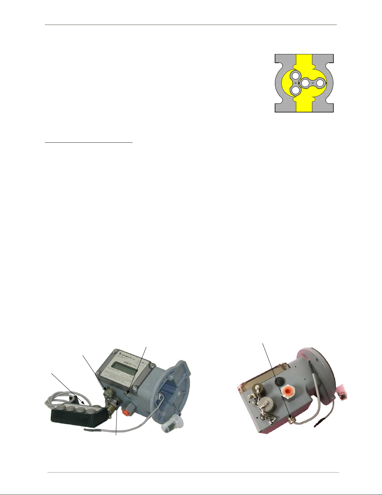
Fig.1 Rotary meter principle
Fig.2 AdEM®-PTZ overview
Pulse Outputs
Portable
Keyboard
RS232 and Keyboard or
RS485 and Keyborad
Scroll Button (Pushbutton)
Fig.3 AdEM®-PTZ Pigtail Output Pulse connection
Pigtail Pulse Output

AdEM™-PTZ
ROMET LTD. 2
How to Specify Model
How it works
The AdEM®-PTZ is a solid-state electronic volume conversion module that is directly coupled to the magnetic housing
of the Romet meter body. The AdEM®-PTZ employs a magnetic sensing device to sense the rotation of the meter’s
outer magnet which produces a high-resolution input that represents the non-converted (UNC - uncorrected)
metered gas volume. The volumetric input pulses are converted to base measurement conditions (COR - corrected)
by compensating for temperature, pressure (live or fixed) and super-compressibility NX-19 or AGA8 or SGERG88 (live
or fixed).
COR = UNC x PFx TFx (Fpv)2 or COR = UNC x PFx TFx FZ
Where: COR = Corrected volume (ft3or m3)
UNC = Uncorrected volume (ft3or m3)
PF= Pressure correcting factor
TF= Temperature correcting factor
(Fpv)2= Super-compressibility correcting factor (Live Z factor for NX-19
method)
FZ= AGA8 or SGERG88 compressibility factor (Live)
The pressure and temperature correction factors are calculated by the formulas as mentioned in section 8. The
temperature is measured by an RTD or IC (optional) temperature sensor located in the temperature well or inlet
differential port (optional) of the meter. Pressure transducer is mounted inside enclosure of AdEM®-PTZ (¼ inch
NPT connector is available for pressure piping arrangement). The optional external temperature sensor location is
recommended for mating the AdEM®-PTZ module to Romet meter bodies that do not have an internal temperature
well.
Both parameter description and values that are integrated by the algorithms of the AdEM®-PTZ firmware (UNC
volume, COR volume, flow rate, date, time, etc.) are displayed on an 8 digit 14-segment semi alphanumeric liquid
crystal display (LCD).
A non-volatile EEPROM memory stores key parameter values, AdEM®-PTZ setup configuration, temperature sensor
calibration data and Audit Trail data in the event of power loss.
AdEM®-PTZ key parameters:
✓Current values of uncorrected and corrected volumes and measured parameters
✓Under/Over limit violation monitoring of Pressure, Temperature and Flow.
✓Present and Previous Day Volumes.
✓Averages, Maximum and Minimum values for pressure, temperature and flow.
✓Peak Flow stamped by date and time.
✓Battery status.
✓Last Hour Indexes stamped by date and time.
✓Malfunctions.
✓Uncorrected Volume Since Malfunction.
AdEM™VER 1 or 2 or 3 characters (letters and number)
specifies version of module.
Number specify Comm Port installed:
PTZ –Pressure, Temperature and Super-X No number –RS232; 1 –RS232 Isolated;
2 –RS485
Note: Type of connections (e.g.: Cannon, PG9 connectors)
can be customized according to user specification.
XXX
PTZ

AdEM™-PTZ
ROMET LTD. 3
In addition to compensating for live pressure and temperature conditions, the AdEM®-PTZ has a low flow volumetric
linearization feature that enhances the rangeability of the Romet meter to 200:1 or better with an error of less than
1.0%. This feature, if activated, is automatically initiated at flow rates below 10% of the Qmax rating for the meter.
RometLink Software
Romet has developed a Windows based user-friendly software tool, RometLink, that runs on a Microsoft Windows
based computer. This software tool enables users to take full advantage of AdEM®-PTZ device’s advance features
and makes it easy to operate, configure and manage the device and data.
RometLink software is the primary user interface and tool for Setup/Configuration, Calibration and
Data/Parameter retrieval.
Fig.5 RometLink software Main window
Fig.4 Accuracy Curves

AdEM™-PTZ
ROMET LTD. 4
Highlights of RometLink software are:
✓Microsoft Windows based.
✓Use either as device management (configuration and calibration) tool or combine with advance features to
make a powerful device and data management system
✓Local or remote communication with Hayes command set compatible modems, Cellular modems
✓One-way communication with automated dial out capability.
✓Communication error log.
✓Events and alarm logger functions.
✓Interval and Daily logger functions.
✓Data export to Microsoft Excel or as PDF file for use by different departments as per individual
requirements.
✓Multilevel user passwords for security
✓Online help files for quick reference and use of software
The “LOG ON” password to RometLink software is different than the keyboard password. For default
software “LOG ON” password, please refer to “READ ME” file on CD or the “RometLink software password
and module access code” document.
Audit Trail:
✓INTERVAL Log: 256 days of hourly Intervals with 4 items configured or 64 days of hourly intervals with
21 items configured. Other configurations of 5 to 10 items are available. See RometLink
Help files and Intervals Log window below for details (Fig.6).
Fig.6 Interval Log window
WARNING!
WHEN CHANGING INTERVAL ITEMS, OLD AUDIT TRAIL WILL BE DELETED AND CLEARED. DOWNLOADING OF
AUDIT TRAIL MUST BE DONE BEFORE CHANGING AUDIT TRAIL CONFIGURATION IN ORDER TO SAVE
PREVIOUS DATA.

AdEM™-PTZ
ROMET LTD. 5
✓DAILY Log: 1024 days with fixed 8 items. See RometLink Help files and Daily Log window below for
details (Fig.7).
Fig.7 Daily Log window
✓EVENT Log: 166 events. See RometLink Help files and Event Log window below for details (Fig.8).
Fig.8 Event Log window
✓ALARM Log: 102 alarm events. See RometLink Help files and Alarms Log window below for details
(Fig.9).
Fig.9 Alarm Log window
For more details of software functions, please refer to online help.

AdEM™-PTZ
ROMET LTD. 6
AdEM®-PTZ Typical Application
AdEM®-PTZ can be used in a variety of ways. It can be used as a stand-alone device which can be configured or
evaluated by portable keyboard. For ease of operation and advance functions, it is recommended to use Romet
RometLink communication software either through using direct cable connection to the computer (RS232 or RS485),
or remotely by using a Hayes compatible modem connection (including wireless modem).
A typical application scheme is given below.
Implemented Modbus protocol (type RTU) makes AdEM®-PTZ available for other communication and control
systems, e.g.: SCADA.
Communication link equipment is third party equipment and is the responsibility of the user.
Downloaded data can either be further investigated using RometLink software or can be exported to
Microsoft Excel application/PDF for customer’s own way of utilizing it.

AdEM™-PTZ
ROMET LTD. 7
2. GETTING STARTED
AdEM®-PTZ is usually supplied fully calibrated/preprogrammed and mounted to pressure body as per specifications
of each customer. The AdEM®-PTZ modules can be supplied for Romet pressure bodies as well as other
manufacturers’ pressure bodies. The module, when removed from the box, will be in Normal Display mode only.
When removing loose AdEM®-PTZ modules from the box, never lift by the Magnetic Input Sensor P/N 46-124-
0/49-124-0/46-124-120/49-124-120 or Temperature Sensor Cable P/N 46-303-0.
In Normal Display mode, the display will show the value for the converted (COR VOL) or unconverted (UNC VOL) as
per user specifications.
Keyboard Operation
How parameter display works:
There are two stages of displaying parameters:
-As first, parameter description is displayed –up to 8 characters.
-Secondly, (next press of keyboard scroll buttons ↓↑ or SB), value of the parameter is displayed –up to 8
digits with decimal point if applied.
AdEM®-PTZ comes with a Scroll Button in standard; the portable keyboard is available as an option. The details of
the keyboard are as below:
ESCAPE or CANCEL Normally used to wake up the unit, cancel a dialog or escape a menu or
parameter.
UP Used to scroll up menu items, a parameter list, available parameter
options or increment digit value.
DOWN Used to scroll down menu items, a parameter list, available parameter
options or decrement digit value.
ENTER Used to select a menu, validate a digit value or to select a parameter
option in Setup and Calibration Modes.
When operating in the Normal Display mode the COR VOL or UNC VOL appears on the display. Press the ESC button
to wake up the AdEM®-PTZ and access the first parameter of the Custom Display mode (refer to Section 3, Modes
of Operation). If an alarm or malfunction is present, it will be displayed instead of the Custom Display Mode. To
move to the Custom Display if an alarm or malfunction is displayed, press the ENT button once. While in Custom
Display Mode, the /buttons may be pressed to scroll through the parameters or at any time press the ENT button
to gain access to the main menu. Once in the main menu, the /buttons are used to scroll the program modes.
Press the ENT button to enter a mode or the ESC button to return to Normal Display mode.
Program protection against unauthorized access to the metrological programming (Set Up, Calibration & Proving) of
the AdEM®-PTZ is assured by the combination of a Password and sealable En/Dis Switch (Jumper). Refer to Section
4, Security for further information). A D-size lithium battery produces the intrinsically safe power.
EN
T
ES
C

AdEM™-PTZ
ROMET LTD. 8
Scroll-button Operation
A scroll button (SB) has been provided on the bottom of the AdEM®-PTZ module. When the SB is pressed once, the
module wakes up and enters the Custom Display mode. By repeatedly pressing SB, the user can scroll through the
menu of parameters. If an alarm or malfunction has been activated, it will be shown as the first displayed item. If
the SB is not pressed for approximately 60 seconds, the AdEM®-PTZ will return to the Normal Display mode. For
more details, please refer to Custom Display mode in Section 3, Modes of Operation.
Example of letters: A =
B =
C =
Scroll-Magnetic Sensor
As an option to Scroll Button (SB) can be used Scroll Magnetic Sensor installed inside of enclosure, therefore invisible
to public. Sensor is activated by dedicated magnetic tool eg. magnetic pen, screwdriver or other.
Fig.10 AdEM with hidden magnetic sensor as Scroll Button
Magnet

AdEM™-PTZ
ROMET LTD. 9
AdEM®-PTZ Operation Menu Structure

AdEM™-PTZ
ROMET LTD. 10
3. MODES OF OPERATION
AdEM®-PTZ has the following 7 modes of operation:
Normal Display Mode
In Normal Display Mode, the AdEM®-PTZ:
✓processes the unconverted volumetric input pulses at specific volume intervals
✓measures the gas pressure and temperature at specific volumetric intervals
✓converts the metered volume to specific units of measurement (UNC VOL)
✓converts the UNC VOL to the base measurement conditions (COR VOL)
✓adds the unconverted (UNC VOL) and converted volumes (COR VOL) to the appropriate registries
✓generates the volumetric output pulses (COR VOL, UNC VOL and/or alarm)
✓determines limit violations, alarms
✓on hourly basis saves in non-volatile memory current UNC VOL and COR VOL
✓determines Peak Flow and saves it stamped with time and date in non-volatile memory
✓processes audit trail data and saves it in non-volatile memory
Depending on the selection made in the Set up Mode under “SET DISP” either the COR VOL or UNC VOL will appear
on LCD. If the display is blank, a critical alarm condition exists, or the battery power has expired (refer to section 9,
ALARMS & MALFUNCTIONS).
The display will always automatically revert to the normal display. Password or En/Dis Switch (Jumper) protection
does not apply to this mode.
Latest models of AdEM can have volume units/multipliers indicators visible on a Nameplate in a form
of arrows pointing towards the specific locations of the display. While Uncorrected or Corrected
volume, one of three locations has a dot lighted up correlating with an arrow marked by the appropriate
multiplier: CF or CCF or MCF.
Example:
∆∆ ∆
MCF CCF CF
The dot associated with CCF arrow is lit up, therefore, the unit/multiplier for displayed volume is CCF
(x100CF).
This feature applies only to Imperial configuration under Normal Mode.
Custom Display Mode
The Custom Display mode allows the user to scroll a customized menu of up to 15 parameters selected from the Full
Display Mode and any activated alarms. To enter the Custom Display mode from the Normal Display Mode, press
the ESC button or Scroll button (SB). Press the /buttons or the SB repeatedly to scroll through the list. The
AdEM®-PTZ will revert to the Normal Display Mode after approximately 60 seconds if no buttons are pressed. The
Custom Display menu is configurable in the Set Up Mode (refer to Section 5, Set Up) Configuration of this mode is
protected by Password. Password or Program Switch protection does not apply to access this mode.

AdEM™-PTZ
ROMET LTD. 11
Full Display Mode
The FULL DISPLAY Mode provides a comprehensive menu of the parameters that are stored by the AdEM®-PTZ. FULL
DISPLAY mode is accessible through keyboard. When FULL DISPLAY mode is accessed and active, AdEM®-PTZ will
revert to the Normal Display Mode after approximately 60 seconds if no buttons are pressed. Password or Program
Switch protection does not apply to access this mode.
Refer to flowchart Full Display in appendix for complete list of parameters.
Set Up Mode
The Set Up mode allows the user to change some parameters of the AdEM®-PTZ from the factory default settings
(refer to Section 5, SET UP mode). Access to this mode is protected by a password and sealable program switch
(refer to Section 4, SECURITY). A 3-digits employee identification code is also needed as a requirement of the Event
Logger function. When Set up mode is accessed and active, AdEM®-PTZ will revert to the Normal Display Mode after
approximately 60 seconds if no buttons are pressed.
Calibration Mode
The Calibration mode allows the user to calibrate the accuracy of the temperature and/or pressure sensors (refer to
Section 6, CALIBRATION). Access to this mode is protected by a password and sealable Program Switch (refer to
section 4, SECURITY).
Proving Mode
The Proving Mode permits an accurate and efficient proving of a meter by providing a precise, selectable pulse
output (refer to section 7, PROVING). The output unit defaults to be ft3or m3, based on the selection (imperial or
metric) programmed from the "SET MET" menu in the Setup Mode. Since the Proving Mode allows the user to
choose the pulse weight resolution (single displacement) in combination with the precise volumetric pulse, the proof
of the meter accuracy can be verified with a reduced test volume. Access to this mode is protected by a password
(refer to section 4, SECURITY). Proving can be also performed using pushbutton –see chapter 7 PROVING.
Testing Mode
The Testing Mode verifies both the sensors (temperature and pressure), volume conversion accuracy (refer to
section 8, TESTING), and Output Pulse physical connection. In addition, the Testing Mode checks the functionality
of several key program routines and therefore, provides a diagnostic test. Access to this mode is protected by a
password (refer to section 4, SECURITY).
Communication Mode
Communication Mode is triggered by RS232 or RS485 signal from connected computer or modem. Message “LINK”
is displayed on Display until communication is finished. If by any occasion communication between AdEM®-PTZ and
computer/modem is broken, corrector will revert to Normal Mode after timeout.
Access by keyboard and Scroll-Button is disabled under Communication Mode. Input Pulse collection and
processing, Volume Index updates and Output Pulse generation continues as normal.

AdEM™-PTZ
ROMET LTD. 12
4. SECURITY
The AdEM®-PTZ module is protected with an access code and the software is protected by a password.
Password
To enter software:
•Default password for limited level user is: 55555.
•Default password for standard Administrator level user is: ROMET.
•Default password for Service level user is: SERVICE.
•Default password for full Administrator/ Superuser level: available for Authorized users only.
To download update data (except Event Log update) from module (corrector) default access code is: 33333.
Above passwords and access codes can be changed by RometLink software.
The following menu item can be accessed with different level of Passwords,
Limited level User
The following menu items are available with the limited user password.
Standard Administrator level User
The following menu items are available with the Standard Administrator user password.

AdEM™-PTZ
ROMET LTD. 13
Service level User
The following menu items can be accessed with the service level user password.
Module Access code
The module can be accessed with the help of a Keypad for Setup Mode, Calibration Mode, Proving Mode and Testing
Mode (the word PASSWORD appears on the display). The password is a five-digit number (default value of 33333 or
pre-customized) that is entered in the following manner:
PASSWORD
Press (Up key) three times 3
Press ENT to move to the next digit
Press (Up key) three times 3
Press ENT to move to the next digit
Press (Up key) three times 3
Press ENT to move to the next digit
Press (Up key) three times 3
Press ENT to move to the next digit
Press (Up key) three times 3
Press ENT to complete the password
33333 Password is preset by factory. It can be changed using RometLink software by user logged on
administrative level. Otherwise, the password must be specified at the time of ordering.
While using RometLink software the same password must be entered to change Setup, Calibrate or download
restricted data. Refer to software Help files for more information.
The “LOG ON” password to RometLink software is different than the keyboard password. For default
software “LOG ON” password, please refer to “README” file on CD or the “RometLink software password
and module access code” document.
Program Switch (Jumper)
To protect the AdEM-PTZ module from unwanted changes to Metrological parameters, there are two options.

AdEM™-PTZ
ROMET LTD. 14
I) By Jumper
The sealable Program Switch (sometimes referred as Program Jumper) is located on Main Board (refer to Fig.12)
available after opening of module’s lid. When cover/module’s lid is installed and sealed (with two sealable screws
plus wire seal) on Program Switch Jumper in the “Disable” position, keyboard access to the Calibration Mode and
most of the Setup Mode parameters is prevented, even after entering a password.
Program Switch performs the same function for software Calibration, firmware update, proving by pushbutton, and
pulses generation for AMR testing, preventing uncontrolled change of these metrological sensitive parameters if
Jumper is in “Disable” position.
For Firmware version D05 and later Program Switch in “Disable” position configures Event Logger to Event
Logger Type A, making available to user only limited metrological parameters for configuration. See next
chapter for further details.
II) By Software
Alternatively, while Jumper is placed in Enable position, the same “Disable” flag can be set by RometLink Software
using its “Disable Switch” function. Once Disable flag is set, Enable position of En/Dis Jumper (Switch) become
irrelevant. Such Software way of locking of AdEM simulates perfectly locking by physical means.
At this point, AdEM can be metrological sealed by physical seal on Housing screws or optionally on En/Dis Switch
protective cap.
Unlocking of the AdEM by external Software is not possible, there is no such implementation in AdEM
internal software (firmware).
Once the Program Switch is in Disable position (also by Software means), only the following can be changed in AdEM-
PTZ:
✓From Keyboard:
SETUP MENU:
SET DATE
SET TIME
SET CUST Set customer display
SET U ID Set Unit ID for Modbus protocol only
CALIBRATE MENU:
No Access
PROVING MANU:
Access with Password
TESTING MANU:
Access with password
Sensor
Convert
✓From Software for firmware versions prior to D02:
GAS DAY START TIME
PRESSURE HIGH LIMIT
PRESSURE LOW LIMIT
TEMP HIGH LIMIT
TEMP LOW LIMIT
UNC FLOW HIGH LIMIT

AdEM™-PTZ
ROMET LTD. 15
UNC FLOW LOW LIMIT
ATMOSPHERE PRESSURE
PEAK UNC FLOW reset
MAX GAS PRESSURE reset
MIN GAS PRESSURE reset
MAX GAS TEMP reset
MIN GAS TEMP reset
MAX CASE TEMP reset
MIN CASE TEMP reset
INTERVAL SETTINGS 5 Minute to 24-hour interval period
INTERVAL TYPE Full fields, fixed 4 fields and selectable fields.
INTERVAL FIELD
CUSTOM DISPLAY
DATE AND TIME
SITE LOCATION
CUSTOMER ID
✓D versions prior to D05 are not approved to use in Canada for legal metrology purpose.
✓From Software, for firmware versions D05 and higher, some of the parameters are protected by Event
Logger, Password and Hardware Switch. Other metrologically significant parameters are protected by Event
Logger Type A and Password, therefore they are available for change when Hardware Switch is set in Disable
position. These parameters can be configured by RometLink software only. Refer to Measurement Canada
document S-EG-06 for Event Logger Type A (self-contained Event logger) information.
✓See Table 1 –Romet products Standard Setup Parameters for parameters monitored by Event Logger
overall and protected by Event Logger type A.
How to ENABLE/DISABLE Program Switch
To gain full access to Setup Mode or Calibration Mode, Program Switch Jumper must be located on “En”position.
Following is the procedure how to En/Dis Program Switch.
Fig.11 Location of Program Switch
(Jumpers) –overview
Fig.12 Location of Program Switch (Jumpers) –
close-up view
Right side connection: Enable (En)
Left side connection: Disable (Dis)

AdEM™-PTZ
ROMET LTD. 16
WARNING!
SERVICE PERSON MUST BE STATIC FREE PRIOR TO SERVICING THE UNIT
Tools and parts required for servicing Program Switch:
-Screwdriver Phillips No. 2
-Cutter Pliers
-440-nut driver
Care should be taken to not damage the cables.
If AdEM-PTZ was metrological sealed, the seal must be broken to perform the Program Switch service.
Procedure to “Enable” Program Switch disabled by Jumper:
1. Remove the seal screws and switch protector plate if installed.
2. Connect the jumper to the “Enable” position.
3. Full access to Calibration and Set Up modes is now available.
Procedure to “Disable” Program Switch by Jumper (hardware method):
1. Connect the jumper to the "Disable" position.
2. Install switch protector plate and seal screws along with wire seal (if required).
Procedure to “Enable” Program Switch disabled by Software
1. Remove the seal screws and switch protector plate if installed.
2. Set hardware switch (Jumper) to “Disable” position in order to make “Enable” position relevant
3. Reset hardware switch back to “Enable” position and metrological changes can be done
4. AdEM®-PTZ is ready again for using “Software Disable Switch” procedure or for hardware method.
Procedure to “Disable” Program Switch by Software (alternative to hardware method):
1. Initial position of the Jumper of Program Switch must be in ”Enable”. This is a Standard Factory Setting.
2. Using RometLInk perform “Disable Switch” from “Talk to Unit”. “Enable” position to become irrelevant.
3. AdEM-PTZ is ready for metrological sealing.
Event Log Type A
AdEM-PTZ with Firmware version D05 and higher provides Event Logger Type A approved by Measurement Canada
as a Metrological Sealing feature.
Selected set of metrological parameters can be modified even hardware Program Switch is set to “Disable”.
Once Event Logger Type A is full, it becomes locked and no any changes can be register in. Therefore, no changes
to parameters can be performed as well. Further changes to the parameters can be done only if Logger itself is
open for changes.
Opening of Event Logger Type A is considered as Verification Triggering Event. Metrological Seal must be broken
and Program Switch must be set “Enable” in order to perform Event Logger UPDATE function, which will open it
for further changes. New Event Logger records will be registered as per FIFO (First In First Out) rule. UPDATE
function is protected by dedicated password. After opening Event Logger Type A, AdEM-PTZ must undergo
Metrological Verification followed with setting Program Switch “Disable” and installation of Metrological seal.

AdEM™-PTZ
ROMET LTD. 17
Table 1. Event Logger Parameters. Parameters marked CFG are configurable, registered in Event Logger Type A,
while Program Switch is set “Disable”.
This manual suits for next models
1
Table of contents
Popular Control Unit manuals by other brands

Bosch
Bosch Rexroth IndraControl S67 Series Application description

MikroTik
MikroTik R11e-LoRa9 quick guide

Graco
Graco CleanShot 287727 instructions

Vixen Horns
Vixen Horns VXA7468C installation guide

WIDE Automation
WIDE Automation WALR 24-2A operating instructions

TII network technologies
TII network technologies 821 Installation

Siemens
Siemens ET 200S 1SI Function manual

Rockwell Automation
Rockwell Automation Allen-Bradley FLEX 5000 Series installation instructions

GEM
GEM 566 operating instructions

Honeywell
Honeywell RMG 213 OPERATING AND MAINTENANCE INSTRUCTIONS/ SPARE PARTS

Emerson
Emerson Neotecha Sapro Installation and maintenance instructions

HPControl
HPControl 3M Series user manual