Surface Mount Adaptor
PRIOR to USE
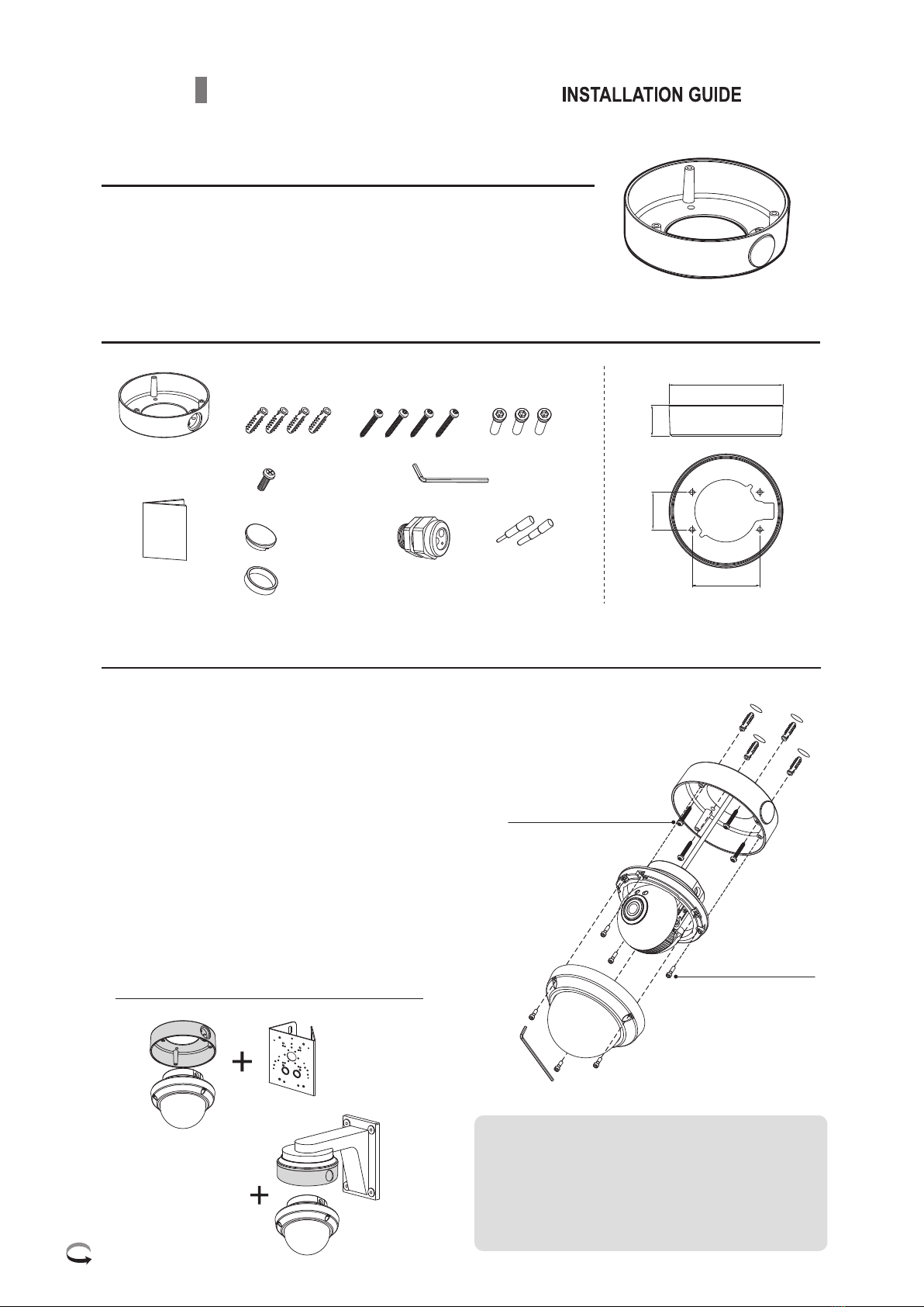
PARTS SUPPLIED
SPECIFICATION
INSTALLATION
Install the mount onto a strong structure such as a concrete, etc.
Use the supplied accessories when installing the mount to a structure,
make sure that all the screw parts are metallic.
Follow the mounting instructions and refer the application mounting
accessories.
Assembly Screw
Screw
3mm(Q’ty:1)
4x14mm(Q’ty:3)
PM 2.5x6mm
(Q’ty: 1)
DIMENSION
(unit: mm)
Mount Adaptor
Instruction Guide
L-Wrench
APPLICATION
37.5
Assembly Screw
(4x14mm)
Mounting Screw (4x30mm)
Supplied in the dome unit
1. Locate the mounting template at the installation position and drill the ceiling or wall if needed.
2. Open the dome cover by loosening screws. Use the torque wrench supplied.
3. Place the surface mount on pre-drilled position and fix it through using mounting screws.
Assemble the cable pipe, otherwise tighten a pipe hole cap.
4. Route the power cable to the connecting place.
5. Affix the dome base unit to the surface mount
using the assembly screws(4x14mm).
Before fixing the dome base, make sure the
assembly holes should be aligned with
the surface mount assembly holes.
6. Set the camera’s viewing angle and adjust
zoom&focus.
7. Put the dome cover to the dome base unit
and tighten the assembly screws.
Pipe Spacer
(Q’ty: 1)
Pipe hole Cap
(Q’ty: 1)
Construction:
Environment:
Dimension:
Weight:
Aluminum cast
Indoor/Outdoor for Vandalproof dome
140(W)x37.5(H)
220g (0.49 lb)
Pole mount adapter
(mounting on the
pole-like structure)
Wall mount bracket
(mounting on the wall)
Ø140
46
83.5
* The vandalproof dome is not
included in this package.
Cable Gland
Q’ty : 1
Gland hole plug
Ø4.5 (Q’ty:1)
Ø2.7 (Q’ty:1)
Mounting Screw
M4x30mm (Q’ty:4)
Plastic Anchor
6x30mm (Q’ty:4)
Please Turn Over


