manuals.online logo
Brands
  1. Home
  2. •
  3. Brands
  4. •
  5. Bosch
  6. •
  7. Receiver
  8. •
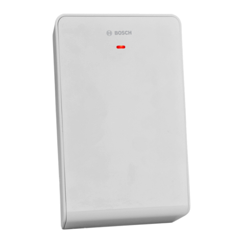
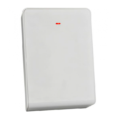
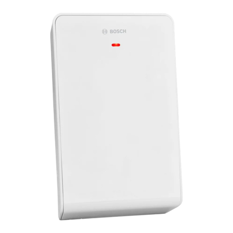
  9. Bosch RF3222E User manual

Bosch RF3222E User manual

Installation Instructions
for the
RF3222E RF Receiver
1.0 General Information
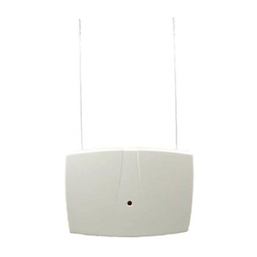
The RF3222E RF Receiver allows the use of wireless devices when
using the DS7400Xi Control Panel.
2.0 Specifications
• Dimensions (H x W x D): 10.8 cm x 15.2 cm x 3.1 cm
• Operating Temperature: 0°C to +65°C
• Frequency: 433.42 MHz
• Power Requirements: 12 VDC, 30 mA, nominal
•Compatible Control Panels: DS7400Xi revision 4.03 or
higher.
•Compliance: Changesormodificationsnotexpresslyapproved
byBoschSecuritySystemscan voidtheuser's authoritytooperate
the equipment.
3.0 Mounting
3.1 Mounting Considerations
•The receiver should be mounted in a central location in regard to
all wireless sensors, whenever possible.
•The receiver should be mounted on a vertical surface with at
least 25 cm clearance for the antennas.
•Avoid mounting the receiver in areas with significant metal or
electrical wiring, such as furnace rooms and utility rooms. If this
is unavoidable, mount the receiver with the antennas extending
above any metal surface.
•Avoid mounting the receiver in areas where it may be exposed to
moisture.
• Reception distances are generally improved with higher mounting
locations and with no metal objects near the antennas.
3.2 Wall Tamper Setup (Optional)
To enable the wall tamper switch, follow the procedure below. If
use of the wall tamper is not desired, proceed to Section 3.3.
• Remove the outer cover of the receiver (see Figure 1) and set it
aside.
Insert screwdriver here
and press in
Figure 1 - Removing the outer cover
• Remove the inner cover (see Figure 2) by pressing the latch.
Press Latch
to remove Inner Cover
Cover Tamper
PWR BU S
+ - + -
ADDR
SUPV
Figure 2- Removing the inner cover
• Move the wall tamper jumper as shown in Figure 3.
W
a
l
l
T
a
m
p
e
r
J
u
m
p
e
r
Wall Tamper disabled
(Default Position) Wall Tamper enabled
Jumper left on pin for storage onl
y.
PWR BUS
+ - + -
ADDR
SUPV
Figure 3 - Wall Tamper Jumper
• Replace the inner cover.
• Place the spring from the hardware packet over the shaft of the
tamper switch located on the back of the receiver (see Figure 4).
Rear of Receiver
Figure 4 - Installing the Tamper Spring
Note: Gently press the spring onto the tapered shaft. Do not force
it down onto the shaft.
3.3 Mounting the Receiver
• Determine the mounting location of the receiver.
Note: Prior to mounting, test the receiver with transmissions from
around the installation to verify reception.
• If not already done, remove the Outer Cover from the Receiver
(see Figure 1) and set it aside.
• Place the receiver base on the wall at the desired mounting
location and mark the two mounting holes (see Figure 5).
Bus and
Power
Connector
Antenna Connectors
Cover
Tamper
Switch
Mounting Holes
LED
PWR BUS
+ - + -
ADDR
SUPV
Figure 5- Receiver with outer cover removed
• Drill holes and install anchors (supplied) if necessary.
• Secure the receiver base to the wall with screws (supplied).
• Insert an antenna into the outside terminal on two of the antenna
connectors as shown in Figure 6. Tighten screws to secure the
antennas.
One Antenna
must mount
here and point
upwards.
Use one
of these
locations
for the
second
Antenna
Preferred
Location
(provides polar
diversity)
Figure 6- Connecting Antennas
Note: The remaining antenna connector and the remaining holes
in the used Antenna connectors are not used.
3.4 Setting Receiver Options
Changing these settings will require that the power to the
receiver be removed and then reapplied for the changes to
take effect. For more detailed information, refer to the
Wireless Reference Guide for the DS7400Xi Control/
Communicator.
• Set the Supervision Option as appropriate:
Supervision Supervision = 2 Hours
Supervision = 12 Hours
Jumper left on pin for storage onl
y.
(Default)
PWR BUS
+ - + -
ADDR
SUPV
Figure 7 - Supervision
• Set the Receiver Address Option as required:
This is Receiver # 1
(Default)
This is Receiver # 2
Address
Jumper left on pin for storage onl
y.
PWR BUS
+ - + -
AD DR
SU PV
Figure 8 - Address
4.0 Wiring and Power Up
4.1 Wiring the Receiver to the Control Panel
Note: A DS7430 or a DS7436 Multiplex Module is required to
connect an RF3222E receiver to a DS7400Xi control panel.
• Disconnect power to the control panel.
• Connect the DS7430 or DS7436 Multiplex Module terminals to
the RF3222E receiver’s terminals as shown in Figure 9, using a
minimum diameter of 0.8 mm solid wire or 1.0 mm stranded wire.
Wire length between the receiver and the control panel should
not exceed 300 m. Adding additional devices to the bus may
reduce the maximum distance. Shielded cable is not
recommended. Do not use twisted pair wire.
• If using a DS7436 Multiplex Module, either bus block may be
used. If using two receivers and the DS7436 Multiplex Module,
either or both bus blocks may be used.
D
S7430 or DS7436
Power Bus PWR BUS
RF3222E
+-+- +-+-
Figure 9- Connecting to the Multiplex Bus
• Replace the outer cover.
• Apply power to the control panel. The red LED at the center of
the receiver should light.
4.2 LED Status
Table 1 describes the status of the receiver based on the LED
condition.
LED
Condition Meaning
On The receiver is functioning normally.
Off A power failure has occurred or the receiver
is not wired correctly.
Turns Off
Momentarily The receiver acknowledged receiving a
message from a compatible transmitter.
Flashes
Rapidly for
less than
1 minute
The receiver is being programmed with zone
and transmitter IDs from the compatible
panel. This condition will occur upon
initialization (power-up) of the system or
when new zone information has been
programmed into the system. The rapid
flashing should last for less than one minute.
Flashes
Rapidly for
more than
1 minute
The receiver has failed power-up self tests.
Replace receiver.
Table 1 - LED Status
5.0 Panel Programming
Forprogramming information, refer to theWirelessReferenceGuide
for the DS7400Xi Control/Communicator.
© 2004 Bosch Security Systems
130 Perinton Parkway, Fairport, New York, USA 14450-9199
Customer Service: (800) 289-0096; Technical Support: (888) 886-6189
03/04
RF3222E Installation Instructions
P/N: 41054D Page 2
Other Bosch Receiver manuals

Bosch Radion B810 User manual

Bosch

Bosch Radion B810 User manual

Bosch RFRC-OPT User manual

Bosch

Bosch RFRC-OPT User manual

Bosch Radion B810 User manual

Bosch

Bosch Radion B810 User manual

Bosch RF3212E User manual

Bosch

Bosch RF3212E User manual

Bosch WE800EV2 RF User manual

Bosch

Bosch WE800EV2 RF User manual

Bosch FA400 User manual

Bosch

Bosch FA400 User manual

Bosch LR 6 User manual

Bosch

Bosch LR 6 User manual

Bosch RFRC-OPT User manual

Bosch

Bosch RFRC-OPT User manual

Bosch GML 10,8 V-LI User manual

Bosch

Bosch GML 10,8 V-LI User manual

Bosch LE10 User manual

Bosch

Bosch LE10 User manual

Bosch LTC 8561 Series User manual

Bosch

Bosch LTC 8561 Series User manual

Bosch LE10 User manual

Bosch

Bosch LE10 User manual

Bosch LE10 Installation and operating instructions

Bosch

Bosch LE10 Installation and operating instructions

Bosch LR30 User manual

Bosch

Bosch LR30 User manual

Bosch EKOM 11 User manual

Bosch

Bosch EKOM 11 User manual

Bosch RE005EV2 User manual

Bosch

Bosch RE005EV2 User manual

Bosch LR 2 Professional User manual

Bosch

Bosch LR 2 Professional User manual

Bosch Professional LR 60 User manual

Bosch

Bosch Professional LR 60 User manual

Bosch Radion B810 User manual

Bosch

Bosch Radion B810 User manual

Bosch Professional GCT 30-42 User manual

Bosch

Bosch Professional GCT 30-42 User manual

Bosch RFRC-OPT User manual

Bosch

Bosch RFRC-OPT User manual

Bosch Coach smartPanel NAFTA 7 620 210 046 Technical manual

Bosch

Bosch Coach smartPanel NAFTA 7 620 210 046 Technical manual

Bosch RE005EV2 User manual

Bosch

Bosch RE005EV2 User manual

Bosch LR 1 Professional User manual

Bosch

Bosch LR 1 Professional User manual

Popular Receiver manuals by other brands

LF Engineering L-600S quick start guide

LF Engineering

LF Engineering L-600S quick start guide

Philips MX735 Specifications

Philips

Philips MX735 Specifications

Hallicrafters S-38C Operating and service instructions

Hallicrafters

Hallicrafters S-38C Operating and service instructions

CaryMart 0020695 manual

CaryMart

CaryMart 0020695 manual

FTE UNIVERS U4150 instruction manual

FTE

FTE UNIVERS U4150 instruction manual

Sennheiser EK100G2 operating instructions

Sennheiser

Sennheiser EK100G2 operating instructions

Roadstar TRA-2988 instruction manual

Roadstar

Roadstar TRA-2988 instruction manual

Inclusive Technology it-Receive quick start guide

Inclusive Technology

Inclusive Technology it-Receive quick start guide

Onkyo DR-L50 Service manual

Onkyo

Onkyo DR-L50 Service manual

technetix AIMA-FRAS Product user manual

technetix

technetix AIMA-FRAS Product user manual

Harman Kardon AVR 630 Test report

Harman Kardon

Harman Kardon AVR 630 Test report

Sony STR-V200 - Fm Stereo/fm-am Receiver operating instructions

Sony

Sony STR-V200 - Fm Stereo/fm-am Receiver operating instructions

Arexx BS-500 manual

Arexx

Arexx BS-500 manual

HanRongDa HRD-737 user manual

HanRongDa

HanRongDa HRD-737 user manual

FUTABA R304SB-E manual

FUTABA

FUTABA R304SB-E manual

RadioLink R4F instruction manual

RadioLink

RadioLink R4F instruction manual

Sony STR-DN1060 reference guide

Sony

Sony STR-DN1060 reference guide

Altronix eBridge PLUS eBridge8PCRM installation guide

Altronix

Altronix eBridge PLUS eBridge8PCRM installation guide

manuals.online logo
manuals.online logoBrands
  • About & Mission
  • Contact us
  • Privacy Policy
  • Terms and Conditions

Copyright 2025 Manuals.Online. All Rights Reserved.