Roper 20inch User manual

20:‘30”and 36”
Electric Cooktops
IMF’ORTANT:
Installer: Leave Installation Instructions wth the homeowner.
Homeowner: Keep Installation Instructions for future reference.
Save Installation Instructions for local electrical inspector’s use.

ev&tt,mg “&essary 101 c&ect
~“stal,ar,o”. It IS the reswnslblhty of
the installer 10 comply &th mstallatmn
clexance~ spenllsd on the senallrahng
plate The senal/rabng plate IS located
on the bxttJm tif the cooktop.
Check the locanon where the
cooktop XVIII be mstalled. The locallo”
should be away from strong draft areas.
such as ,vmdows, doors and strong
heanng vents OI fans The cwktop
should be lxated Ior convement use III
the kitchen.
ALL 0PEN:NGS IN THE WALL OR
FLOOR WHERE THE COOKTOP IS TO
BE INSTALLED MUST BE SEALED.
Electriral ground IS requned. See
“Elactncal reqwements”
Important: Observe all governing
codes and ordinances.
Nope. The clearances specliled are lor
cambusttble walls and materials that
have a dens0 of 20 01more pounds
per cubx foot. No evaluatmn ol
clearances has been made Ior
mstallarmns adjacent to matenals That
are less than 20 pounds per cubic loot
or to plastic tiles and sheeting.
Countertop opening dimensions that
are shown must be used. Given
chmensmns are m,mm”m clearances
and prowde the requred 0’ clearance.
Cabipet storage above the
making surface should be avoided.
II cabinets are already installed,
reduce the hazard of reaching over a
heated cooking surface by mstalling
a range hood.
The range hood should extend a
minimum of 5” out from the bottom
01 the cabinets.
NOTE:
It is the customer’s responsibility:
- To centact a qualified electrical
installer.
. To assure that the electrical
installation is adecruete and in
conlormance with -National
Electrical Code ANWNPPA 70.
latest edition’, and local codes
and ordinances.
Tools and
materials needed
for installation:
Mobile home installation:
The mstallatmn of this cooktop must
conform to the Manufactured Home
Constructmn and Safety Standards, Tide
24 CFR, Part 3280 (lormerly the Federal
Standard for Mobile Home Construction
and Safety, Title 24, HUD, Part 26’0)
A lour-wre power supply cord must be
used I” a moblIe home mstallatron. The
apphance wlrlng wll need to be
revlsed. See ‘“Electrical requrements”.
Copies of the standard hsted above may
be obtamed from:
‘National Fire Protection Assodation
Battery March Park
Qtincy Massachusetts 02169
20” Cooktop
24” min. base cabinet is required. If
cabinet has a drawer, a 3-l/2’ depth
clearance from the countertop to the top
01 the drawer (or other obshuctm”) 1”
the base cabmet 1s requred I I
For new and replacement installations:
Panel A

30”Cooktop
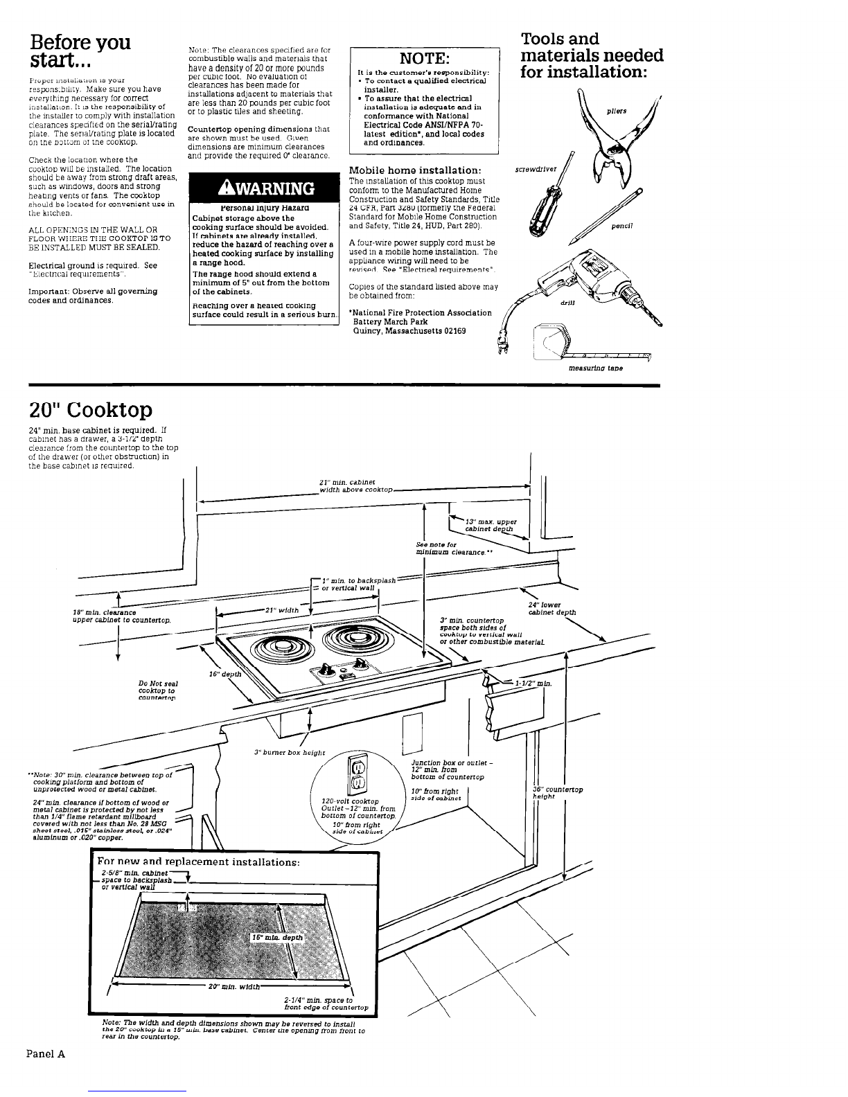
30” min. base cabinet 1s requred. It
cabmet has a drawer, a 3-112’ depth
clearance from the countertop to the top
of the drawer (or other obstiuction) III
the base cabmet 1s reqmred.
Electrical
requirements
Electrical Shock Hazard
. Electrical ground is required on
this appliance.
n
Improper connection ol the
equipmenr.grounding conductor
can result in fire. electrical shock.
01 other personal injury.
. Check with a qualified
electrician if you are in doubt as
to whether the appliance is
properly grounded.
mDo Not use an extension cord with
this appliance.
. Do Not have a fuse in the neutmL
Gilure to follow these instructions
:ould result in a lire. electrical
shock or other personal injuy.
120 Volt -
20” CooktoD
(Power supply cord ar?ached.)
A 120.volt, 60-Hz, AC only, 15. 0120
ampere, lused electruzal supply 1s
required (Tmedelay fuse or arcut
breaker 1s recommended.) It 1s
recommended that a separate clrcut
serwng only t!us applrance be prowded
Recommended
grounding method
Do Not, under any circumstances,
remove the power supply cord
grounding prong.
For your personal safety, this apphancc
must be grounded. This apphance 1s
equpped with a powa supply cord
havmg a J-prong groundmg plug To
mln,m,ze possible shock hazard. the
cord must be plugged mto a matmg,
3.prong groundmg type wall receptacle,
grounded ,n accordance with the
Nabonal Electrical Code, ANSVFPA 70
latest edition, and local codes and
ordmances (See Figure 1 ) If a matmg
wall receptacle 1s not awlable, ,t IS the
personal responslblhty and obhgatlon o,
the customer to have a properly
grounded, &prong wall receptacle
Installed by a quahlied clectnaan
240 Volt -
20’, 30” and 36”
Cooktops
(Power
supply
cable attached.)
A
A thwe-wm, single phase, 240.
. volt. 60.Hz, AC only. electrical
suo~lv 1s reoured on a separate 50.
an&e c<, fused on b&h sides of
the hne. Trne-delay fuse or c,~cu,t
breaker 1srecommended. The fuse
s,ze must not exceed the cncut rating
of the appliance spenfled on the serlaW
ratmg plate located on the bottom of
the cooktop
B
THE COOKTOP MUST BE
CONNECTED WITH COPPER
. WIRE ONLY.
C
Wm SIZE must conform to the
. requirements of the Natlonal
Electrical Code ANSVNFPA 70.latest
editIon*, and local codes and
ordmances
D
The apphance should be
. connected directly to the fused
disconnect (or clrcut breaker) box
through flexible, armored 01 non-
rnetalhc sheathed, copper cable The
flexible. armored cable extending from
[he apphance should be connected
:!:rectly to the ,“nctm:, box
E
Locate the ,unct,o” box to allow
. as much slack as possible
between the~unctlon box and the
apphance so that the cooktop can be
moved d servicing 1s ever necessary
Do Not cut the mndult.
F
A ‘JL:hsted candutt connector
must be promded at the ,“ncl>on
’ box.
G
It 1s the personal responslbllw
. and obbgatmn 01 the customa
to contact a qualified electr~clan to
assure that the mstallatmn 1s adequate
and m aonfcxmance vat.b the Nanonal
Electrical Code ANSVNFPA 70.latest
edluon’, and local codes and
ordmances.
Copies of the standard hsted may be
abtaned from lrom:
* National Fire Protection Association
Battery March Park
(luincy, Massachusetts 02169

36”Cooktop
36” min. base cabinet IS requned. I1
cabinet has a drawer. a 3-112’ depth
clearance Irom the countertop to the top
of the drawer (01 other obsrmctm”) in
the base cabinet 1s requned.
For new and replacement installations:
~~~zo~~*gEfTJ
\ \
240 Volt power supply
cable electrical
connection
Electrical Shock Hazard
. Disconnect power to the junction
box.
. This appliance must be connected
lo a arounded. ~ermanenl wirino
system 01 a g&“ding conneao;
should be connected to the
grounding terminal 01 wire lead on
the appliance.
. Do Not connect to the electrical
supply until the appliance is
pennanenlly grounded.
Failure to do so could resell in
elecrrical shock, serious injury, or
death.
A. Where local codes
permit...
connectmg the cnhmet-groundmg
conductor to the neutral (white)
,unctm” box vvne’
Cable hm
Juncrlo” box power s”pply
Cable fmm
BPPIIS”CB
Figure 1
B. Where local codes Do Not
permit...
connecting the cablnet-groundmg
Conductor to the neutral IwhIte)
,unctm” box wire.
* Grounded, cold water pipe must have
metal contmuity to electrical ground and
not be mterrupted bv Dlastlc. rubber or
other electrical lnsu~atlng connectors
such as hoses, httmgs. washer or
gaskets (mcludmg water meter or
pump). Any electrical msulaung
connector should be lumped, as shown
with a length of No. 4 wre securely
clamped to bare metal at both ends.
This apphai~ce IS manufactured with a 1 Connect the green (or bare) apphance
Figure 2
cabmet-cunnected, green 01 bare,
groundmg w,,e
Connect tne applmce cable to the
,unctmn box through a U L -1lsted
C311dU11conncclor
cable w,re vath the neutral
(white) wne 1” the ]u”ct,o” box.
2 Connect the two black w,res Then
connect the two red wires. (See
Flgure 1.)
1. Connect the two black vwes Then
connect the two red wy11es (See
Figure 2.)
2 Connect the green (or bare)
grounding w”e from the apphance to a
grounded w,re I” the IunctIon box “I to
a grounded, copper, cold water p,pe.’
3 Do Not ground to a gas supply or hot
water pipe. Do Not connect to electrical
Figure 3
supply until appliance IS pemlanently
grounded (See Figure 3 )
Panel C

C.
If connecting to a four-
wire (mobile home),
electrical system:
Do Not a,““ect the cabinet-grounding
conductor to the neutral (white),
Now start.. .
With cooktop in kitchen.
All cooktops are inslalled Iollowmg
these steps. The 36” cooktop is shown.
1.
Figure 4
1. Separate rhe green (bare) apphance
cable wres
2. Connect the two black WIIBS. Then
connect the two red wres. (See
Flgure 4.,
3. Connect the green (or bare) ground-
mg wm TOthe grounding w,re I”
the ]unct:o” box
3
insert moktap mto the
OO”“te*op opening center
cook&o I” cutout. Check that the front
of the cooktop IS parallel to the front
edge of the counrertop and at least
1-K Inches back from the front edge
of the countertop and 1 mch from
backsplash or rear wall Lltt up cooktop
and mark location of mountmg holes on
countertop. Remove cwktop from
CUtoUt
Determine which mounting
method you will use. Refer
to Steps 4, 5 and 6.
Wear protectwe eyeglasses when
4
II the burner box nanye will be
. screwed dxectly into the
countertop. jMo”“t,“g SCICWS n;y “01
be supphed w!h all models )
a
Dnll pilot holes at each mark lor
. the screws.
C
Lift cooktop up to at least a 90”
. angle and support the caoktop
securely. Insert a wood screw I” each
of the front and rear corner mou”U”g
holes to fasten burner box flange to
countertop. (Some cooktops may have
a mou”t,“g hole m the center of the
front and rear flanges. Use of center
mou”t,“g holes 1s optmnal.) Do Not
overtlghten screws. Lower cooktop
IntO operat,ng posltlo”
5.
II the burner box nanye will be
naded d~realy into rhe
counterrop. (Flat head nails are not
iuppllid )
a
Dnll p,lol holes al each math lor
. the nals
Pmduct Damage
Do Not hit burner box flange
with hammer.
Hitting the flange with the
hammer could damage the
porcelain finish.
C
Lilt cooktop up to at least a 90”
. angle and support the cooktop
securely Hammer a flat-head “all
through each of the front and rear
comer mountmq holes to fasten burner
box flange to cointertop. (Some
cooktops may have a mountmg hole I”
the center of the lront and rear flanges
Use of center mountmg holes IS
aptmnal ) Do Not hammer nals LOO
t,ghtly to countertop. Lower cooktop
,nto operat,ng posItlo”.
6.
If counrerrop material is
dlllicult Lo drill through (such
as ceramic): (Wood screws or nails
may not be supphed )
Property Damage
Use special care when drilling
through ceramic mateli&.
Ceramic materials may crack
or shatter during drilling.
a
Use a carbide tip dnll bit 10 dnll
. clearance holes through the
countertop matenal at each mark.
b
Reset moktop ~“to cutout and
. ahg” mounting holes wth the
drilled clearance holes
Product Damage
Do Not hit burner box llange
with hammer. I
Hitting the flange with the
hammer could damage the
porcelain linish. I
L. angle and ii&on the cooktop
securely Use a wood screw or flat-
head “all throuoh each of the front and
P rear comer mointlng holes to lasten
burner box flange to countertop
(Some cooktops may have a mounting
hole ,n the center of the front and
IEar flanges Use of center mO”ntlng
holes is o!X,o”al.) Do Not overtlqhten
Optxx~J method Bolts at least 2-l/2
Inches long (awlable from a local
hardware stare) can be used,
depending on the locatm” of the
cooktop mountmg holes.
Panel D

7
Replace the control knobs, dnp
. bowls and surface elements
Place the drip pan ,n the gnddle
openmg, msen the electnc element,
place the gnddle over the element. and
place the cover over the gnddle (for
models so equipped).
8
Make the electr~4 connectmn
. (See “Electrical requrements”
and “Electrical connection” sectmns,
Panel C, for details )
9
. Turnan rhepowersupply.
10
Push m and turn each control
n
knob to the “HI” vas,t,on
Check rhe operat,on of the cooktop
heatmg eiemcnts and mdlcator hghts
Congratulations!
You have just finished
installing yournew, Roper
Cooktop. Keep Installation
Instructions available for
easy reference.
8. 7d.
Numbers
correspond
to steps.
Panel E

If the cooktop
If you need
does not - assistance...
ROPER
Pnnted in U S A
Part No 36.300859-C,? 0~4315475
(C) 1989 Roper Rrar1;’ Benton Harbor, Mlchlgan 49022
This manual suits for next models
2
Table of contents
Other Roper Cooktop manuals
Popular Cooktop manuals by other brands

Omega
Omega OC64TXA Installation and operating instructions

Electrolux
Electrolux 36" Ceramic Use and care guide

Felix Storch
Felix Storch Summit CR2B223G owner's manual

Residentia
Residentia ESATTO ECG6 user manual

GE
GE Monogram ZHU30RSR Dimension Guide

Electrolux
Electrolux EI24EC15KS installation instructions