Before you
start.. .
Proper installation is your
responsibility. Make sure you have
everything necessary for correct
installation. It is the responsibility of
the installer to comply with
installation clearances specified on
the serial/rating plate. The
serial/rating plate is located on the
bottom of the cooktop.
Check the location where the cooktop
will be installed. The location should
be away from strong draft areas, such
as windows, doors and strong,
heating vents or fans. The cooktop
should be located for convenient use
in the kitchen.
ALL OPENINGS IN THE WALL OR
FLOOR WHERE THE COOKTOP IS TO
BE INSTALLED MUST BE SEALED.
Grounded electrical outlet is
required. See “Electrical
requirements”.
Proper gas supply connection must
be available. See “Gas supply
requirements”.
IMPORTANT: Observe all
governing codes and
ordinances. Failure to meet
codes and ordinances could
lead to fire or electrical shock.
20" Cooktop
24” min. base cabinet is required. If
cabinet has a drawer, a 3-112”depth
clearance from the countertop to the top
of the drawer (or other obstruction) in
the base cabinet is required.
“‘Note: 30” min. clearance if bottom
of
wood or
metal cabinet is
protected
by not
less than -‘lame retardant
millboard
covered w.
rot less than No. 28 MSG
sheet steel, .015” stainless steel, or .024”
aluminum 02 .OZO”mpper.
36” min. clearance
between
top of
cooking
pl& and
bottom
of
unprotect6
;ood
or metal cabinet.
The clearances specified are for
combustible walls and materials
that have a density of 20 or more
pounds per cubic foot. No
evaluation of clearances has been
made for installations adjacent to
materials that are less than 20
pounds per cubic foot or to plastic
tiles and sheeting.
Countertop opening dimensions
that are shown must be used. Given
dimensions are minimum clearances
and provide the required 0”
clearance.
Mobile home installation:
The installation of this cooktop must
conform to the Manufactured Home
Construction and Safety Standards,
Title 24 CFB, Part 3280 (formerly the
Federal Standard for Mobile Home
Construction and Safety, Title 24,
HUD, Part 280), or when such
standard is not applicable, the
Standard for Manufactured Home
Installations 1982 (Manufactured
Home Sites, Communities and Set-
Ups), ANSI A225.1 -latest edition,
or with local codes.
Copies of the standards listed above
may be obtained from:
*National Fire Protection Association
Batterymarch Park
Quincy, Massachusetts 02269
**American Gas Association
1515 Wilson Boulevard
Arlington, Virginia 22209
WARNING: If the
information in this manual
is not followed exactly; a
fire or explosion may result
causing property damage,
personal injury or death.
- Do not store or use
gasoline or other
flammable vapors and
liquids in the vicinity of
this or any other appliance.
- WHAT TO DO IF YOU
SMELL GAS
. Do not try to light any
appliance.
. Do not touch any
electrical switch; do not
use any phone in your
building.
. Immediately call your gas
supplier from a neighbor’!
phone. Follow the gas
supplier’s instructions.
1 If you cannot reach your
gas supplier, call the
fire department.
- Installation and service
must be performed by a
qualified installer, service
agency or the gas supplier.
Fire Hazard
Do Not obstruct the flow of
combustion and ventilation air.
Personal Injury Hazard
Avoid installing cabinet storage
above the cooking surface. If
cabinets are already installed,
reduce the hazard of
reaching
over a heated cooking surface by
installing a range hood. The
range hood should extend a
minimum of 5 inches out from
the bottom front of the cabinets.
Reaching over a heated cooking
surface could result in a serious
bum or other personal injury.
Electrical Shock Hazard
It is the customer’s
responsibility:
n To contact a qualified electrical
installer.
n To assure that electrical
installation is adequate and in
conformance with National
Electrical Code, ANSYNFPA 70-
latest edition*, and all local
codes and ordinance.
Failure to do so could result in
fire, electrical shock or other
personal injury.
A
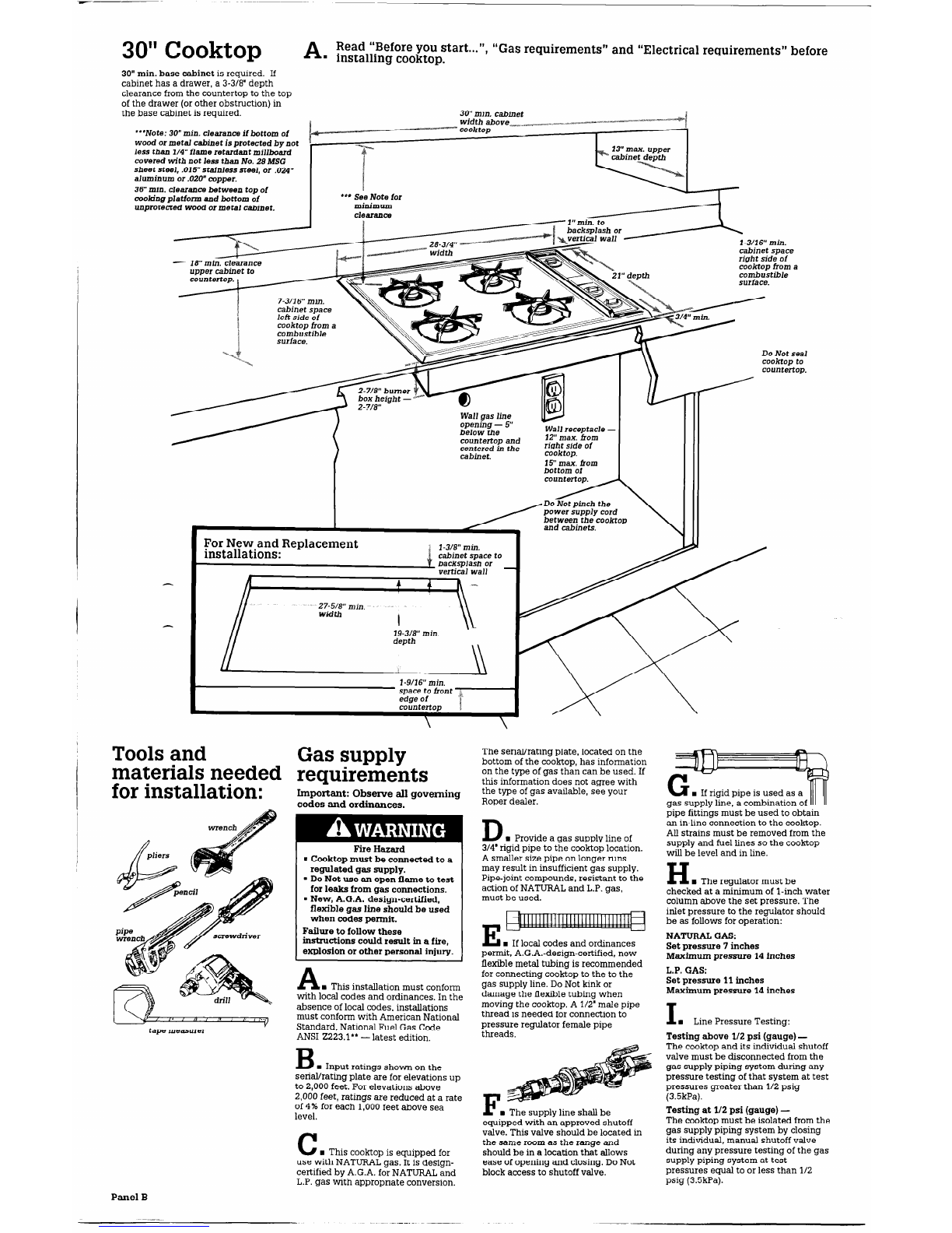
Read “Before you start...“, “Gas requirements” and “Electrical requirements” before
. installing cooktop.
B
Installation dimensions for the 30” cooktop are given on Panel B and for the
n
36” cooktop on Panel C.
21”min or 15” min.
cabinet width above
*__13” max. upper
cabinet depth
clearance.
upper cabinet to
countertop. I
I
i between-adjacent
cooktops.
7-l/4” min. countertop
. ,,.- space both sides of
cooktop to vertical
wall or other
combustible material.
gas line
opening - 5” below
the countertop and
centered in the
cabinet.
I
15”max from
bottom bf I I II
Do Notpinch
the power supply
cord between the \ III
For New and ReplacementFor New and Replacement
installations:installations:
3” min. space to3” min. space to
Note: The width and depth dimensions shown may be reversed to install the 20”Note: The width and depth dimensions shown may be reversed to install the 20”
cooktop in a 15” min. base cabinet. Center the opening from front to rear in the
countertop.
Do Not seal
cooktop to
countertop.
Panel A