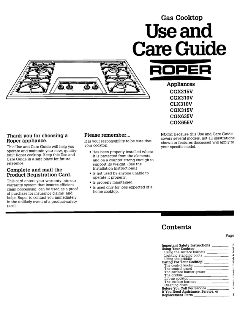
Roper 30” ElectricBuilt-in Glass Cooktop User manual

30” Electric
Built-in
Glass Cooktop
ROPER
.
INIPORTANT:
Installer: LeaveInstallation Instructions with the Homeowner.
Homeowner: KeepInstallation Instructions for future reference.
SaveInstallation Instructions for local electrical inspect013use.

Before you start...
PIiiper
1nstallat10n
1syour
re:,ponstitity. Make sure you have
ev-:rythmg necessary
ior COneCt
mn!,tallatlon.It is the responslblhty
of he mstaller to comply with
m!tallatlon clearances shown.
Grounded electrical supply
1s:equred. See‘Electrical
re(.urements’.
Important:
Observe
all governing codes and
ordinances. Failure to meet codes
and ordinances could lead to fire
or electrical shock.
Th? clearances specified are for
coubustlble wak and materials
th:,t have a densitv of 20or
mere pounds per cubic foot. No
ev;luatlon of clearances has been
madefor mstallations adjacent to
ma:erials that are less that 20
pounds per c&c foot or to plastic
t&s and sheetmg.
New installations -Follow
rec’xnmended timenslons shown.
Replacement installations -
Colmtertop openmg must be
wltnin dunenslons shown. Be sure
tha; front edge of cooktop is at
least l-l/Z’ back from front edge
of countenop.
If clbmet has a drawer. a 4’ depth
clezmce from the countertop to
the top of the drawer (or other
obsimction in the base cabmet)
1srqued
!
Personal Injury Hazard
Cabinet storage above the
cooking surface should be
avoided. If cabinets are
alreadv installed. reduce the
hazard of reaching over a
heated cooking surface by
installing a range hood.
The range hood should extend
a minimum of 5inches out
from the bottom of the cabinets
Reaching over a heated
cooking stuface could result
in a serious bum.
- I
NOTE: )
It is the customer’s
responsibility:
mTo contact a qualified
electrical installer.
mTo assure that the electrical
installation is adequate
and in conformance with
National Electrical Code
ANSI/NFPA 70- latest
edition, and all local codes
and ordinances.
Check locatlon where cooktop wLLl
be mstalled. The locatlon should be
away from strong draft areas, such
as wmdows, doors and strong
heatmg vents or fans. The cooktop
should be located for convement
use m the lotchen.
3o’rmn base cabmet IS
reamred. IJcabinet has a drawer.
_
a 3-112’depth clearance from the’
countertop to the top of the drawer
(or otner otxtructlonj mnase
cabmet is requred.
For
new installations:
For
replacement
installations:
Tools needed
for installation:
PANEL A

Electrical
requirements
Electrical Shock Hazard
sElectricsl ground is x&red
on this appliance.
* Improper wnnection of the
equipment-grounding
conductor can result in fire.
electrical shock, or other
personal injury.
1Check with a qualified
electrician if you are in
doubt as to whether
the appliance is properly
gTounded.
mDo Not use an extension
cord with this appliance.
mDo Not have e fuse in the
neutral 01grounding circuit.
A
fuse in the neutral or
grounding drcult could result
in an electrical shcck.
Failure to follow these
instructions could
result
in a
fire, electrical shock or other
personal injury.
Electrical
connection
A
A thee-wire, single phase,
m240~volt.60-Hz.
AC
or&‘.
electrical supply is required on-a
separate 50-amperecircuit, fused
on both sides of the line. Time-
delay fuse or circuit breaker is
recommended The fuse size must
not exceed the circuit rating of the
appliance specdfiedon the serial/
rating plate located on the bottom
of the cooktop.
B
THE COOKTOPMUST
. BECONNECTEDWITH
COPPERWIREONLY.
C
Wire sizes and wnnections
l
must conform to the
requirements of the National
Electrical Code,
ANSmFPA
70-
latest edition’, and eJllocal wdes
and ordinances.
Copies of the standard listed above
may be obtained from:
l
National Fire Protection
Association
Battery March Park
Quincy. Massachusetts 02169
D
The appliance should be
n
WMected directly to the
fused diswMect (or circuit
breaker) through fetile, armored
or non-metallic sheathed, copper
cable. The flexible, armored cable
extending from the appliance
should be COMecteddirectly to the
junction box.
E
Locate the junction box
1 to allow asmuch slack as
possible between the junction box
and the appliance so that the
cooktop canbe moved if servicmg
is ever necessary. DoNot cut the
conduit.
Elecuical Shock Hazard
1
Disco~ect
power
t0
the
junction box.
l
This appliance must be
co~ected
to a grounded.
permanent wiring system or
a grounding connector should
he connected ta the
grounding termhal or wire
lead on the appliance.
n
Do Not connect to the
electrical supply until the
appliance is permanently
grounded.
Failure to
do somay result
in eltical shock, serious
injury
or death
This appliance is manufactured
with a cabinet-WMected, green or
bare, grounding wire.
Connect
the appliance cable to
the junction box through the l/2’
conduit connector.
Complete electrical connection
according to local codes and
ordinances.
A.
Where local codes
permit...
CoMecting the cabinet-grounding
conductor to the neutral (white)
]unction box wire’
Figure 1
1.Connect the green (or bare)
appliance cable wire with the
neutral (white) wire mthe
junction box.
2. Connect
the two black wues.
Then coMect the two red wires.
(SeeFigure 1.).
B.
Where local codes Do Not
permit...
connecting the cabmetgroundmg
conductor to the neutral (white)
junction box wire:
Figure 2
1.Connect the two black wires.
Then connect the two red wires
(SeeFigure 2.)
2. Connect
the green (or bare)
grounding wire from the appliance
to agrounded wire in the junction
box or to a grounded, copper, cold
water pipe.*
3.
Do Nat ground to a gas supply
or hot water pipe. Do Not connect
to electrical supply until apphance
1spermanently grounded. (See
Figure 3.)
Figure 3
*Grounded.coldw&r muemust
havemetal‘mntrnunytdeiectricaf
croundandnotbeinterruptedby
plastrc,rubberorotherelectrical
msulatmgmnnectorssuchashoses,
firtmas.washersor assketslincludma
lumped,asshown,with s lengthof
No.4wire secuely clampedtobare
metalatbothends.
F
A U.L.- listed conduit
. connector must be provided
at the junction box.
PANELB

Now start...
with
cooktop
in kitchen.
1
Removethe shipping
. materials and tape from the
cc&top. Removethe hardware
6
package from the side of the carton.
1Assembleclamps.
Glasscooktop
F%& 10. Tumonthepowersupply.
11
Pushin and tum each
. control lmoh to the ‘HI
position. Check the operation of the
&c&top heating elements and
indicator lights.
2
Insert the woktop into the
. countertop opemng. Center
the oooktop in the cutout. Check
that the front of the cooktop is
Congratulations!
You have just finisbed
installing your new, Ropez
Cooktop. Keep Installation
Instructions
available for
easy reference.
parallel to the front edge of the “m~emeeroCoYmel
countertop. Checkthat all required
clearances are met.Use a pencilto
7
Insert clamp flange mto the
m
outline the rear of the cooktop on
the axmtertop. slot in the side of the burner
box. Rotate other end of clamp
away from humer box until clamp
is Securely in place. Repeat with
the other clamp.
3
Placetwo of the foam
. shipping
pieces on the
countertop near the cutout.
Removethe cc&top from the
cutout and place it upside down
onthe shipping pieces.
4
Removethe paper backing
, from a small section of the
ioam sealing strip. Placethe strip
l/8’ from the cooktop edge on the
underside of the glass.Continue
until the foam strip completely
outlines the edge of the cooktop.
5
Insert the woktop into the
m cutout and align it with the
pencil outline. Checkthat the
cwktop is parallel to the front
edge of the countertop. Lift the
entire couktop to make adjustments
sothe foam sealing Strip can Seal
properly.
6
4.
Numbers
correspond
to steps.
PANEL C

If cooktop does
not operate. -.
Check that the cncuit breaker 1s
not tnpped or the fuse blown
A more dettied troubleshootmg
checklist is provided in the Use
and Care Guide.
If you need
assistance.. .
When you call you WILIneed the
cooktop model number and senal
number. Both numbers can be
found on the senal/rating plate
located on the bottom of the
cooktop box
Appliances
Part No. 4211867
(1 1990Roper Brand Prmted m U SA
Table of contents
Other Roper Cooktop manuals
Popular Cooktop manuals by other brands

Whirlpool
Whirlpool GJC3055RB00 parts list

Viking
Viking Designer DGVU2004BSS installation guide

Jenn-Air
Jenn-Air PRO-STYLE 8112P342-60 Use and care guide

Zanussi
Zanussi ZEE3921IXA user manual

Bompani
Bompani BO219MA/N Instructions for the installation and use

Teka
Teka GKS 30Gas Instructions for the installation and advice for the maintenance