Ropox 4Single 50-47025 User manual

TF 200.02.0040_ENG
4Single Battery
User manual
This manual must always accompany the product
TF 200.02.0040 / Date 22-05-2023

Page | 2
TF 200.02.0040_ENG
Table of Contents
1. Symbols used in this manual.................................................................................................................. 3
2. General safety........................................................................................................................................... 3
3. General requirements .............................................................................................................................. 5
3.1 Product information.................................................................................................................... 5
3.2 Product description.................................................................................................................... 5
3.3 Intended use.............................................................................................................................. 5
3.4 Intended population ................................................................................................................... 6
3.5 Intended operator ...................................................................................................................... 6
3.6 Basic safety................................................................................................................................ 6
4. Charging the battery ................................................................................................................................ 6
4.1 Recharging procedure ............................................................................................................... 7
4.2 Connection procedure ............................................................................................................... 7
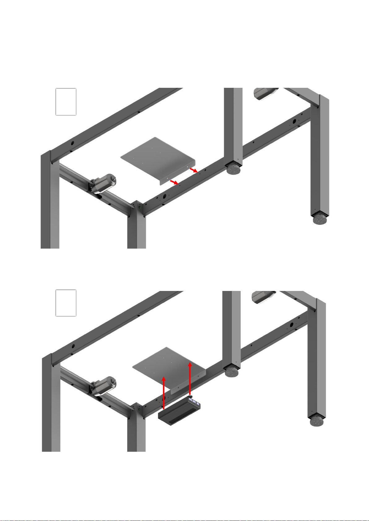
5. Mounting instructions.............................................................................................................................. 8
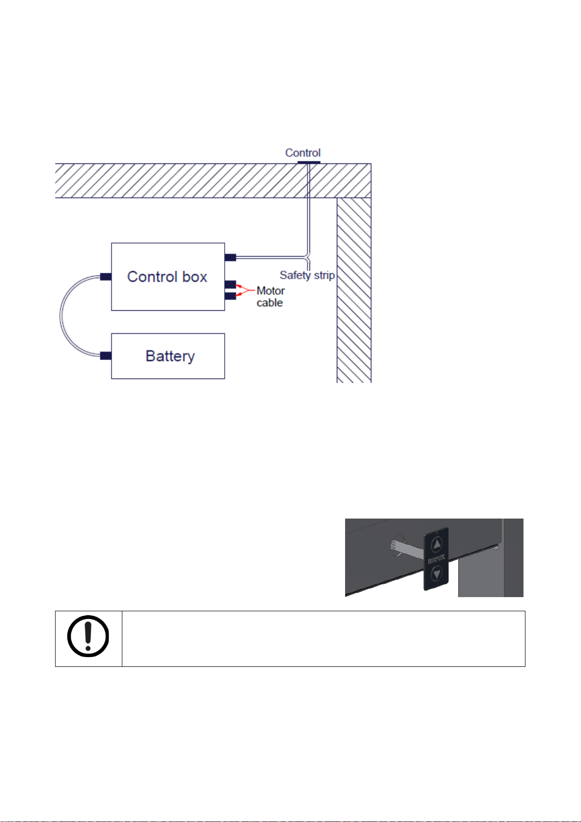
5.1 Electrical component diagram ................................................................................................. 10
5.2 Mounting the control ................................................................................................................ 10
5.3 Testing..................................................................................................................................... 11
5.3.1 Before testing the frame .................................................................................................. 11
5.3.2 Testing the frame............................................................................................................. 11
5.3.3 Testing the safety-strip .................................................................................................... 11
6. Troubleshooting ..................................................................................................................................... 12
7. Cleaning .................................................................................................................................................. 12
8. Maintenance............................................................................................................................................ 13
8.1 Periodic maintenance of the frame.......................................................................................... 13
8.2 Periodic maintenance of the battery........................................................................................ 13
9. Component part list................................................................................................................................ 13
9.1 Accessories, component part list............................................................................................. 14
10. Environmental protection...................................................................................................................... 15
10.1 Packaging, transport, and storage....................................................................................... 15
10.1.1 Packaging........................................................................................................................ 15
10.1.2 Transport ......................................................................................................................... 15
10.1.3 Storage............................................................................................................................ 15

Page | 3
TF 200.02.0040_ENG
1. Symbols used in this manual
Warning Symbol
Indication of potentially hazardous situation. If not avoided, it can result in serious injury or
death.
Caution Symbol
Indication of potentially hazardous situation which may result in minor or moderate injury.
It may also be used to alert against unsafe practices.
Notice Symbol
This symbol is used to notify correct use and handling of the product.
2. General safety
This manual must be read and understood before use.
Always keep this manual in close proximity of the product.
The use, installation and service of this product must follow
this manual to avoid accidents and serious personal injury.
Never use or handle this product in other ways specified in
this manual as it can result in personal safety hazards and/or
cause damage to the product.
Anyone installing and/or using this product either as operator
or user should have the necessary safety information and
access to this manual.
If the supply cord is damaged, it must be replaced by the
manufacturer, its service agent, or similarly qualified
designated person to avoid a hazard.

Page | 4
TF 200.02.0040_ENG
Do not perform repairs, disassembly, or assembly operations,
add-ons, re-adjustments, or modification of the product
beyond what is described in this manual. These must be
carried out by Ropox or Ropox authorized personnel. Do not
perform service while in use.
This appliance can be used by children aged from 8 years
and above and people with reduced physical, sensory, or
mental capabilities, or lack of experience and knowledge if
they have been given supervision, or instruction concerning
use of the appliance in a safe way and understand the
hazards involved. Children shall not play with the appliance.
Cleaning and user maintenance shall not be made by
children without supervision.
Do not use the product if it has defects or has become
damaged before being repaired or replaced.
If the control box makes unusual noise, or smells, switch off
the mains voltage immediately.
Take care that the cables are not damaged.
Unplug the mains cable on mobile equipment before it is
moved.
The products must only be used in an environment that
corresponds to their IP protection. The products must not be
used in explosion hazard environments.
The information in this manual is based on correct installation
in accordance with installation instructions for this product.
Ropox cannot be held liable if the product is used in any way,
that differs from stated in this manual and/or installation
instruction.
Ropox reserve the right to amend this manual and reference
documents without prior notice.

Page | 5
TF 200.02.0040_ENG
3. General requirements
3.1 Product information
Manufacturer
Product models
Part number
Model
Stroke length
50-47025
50-47026
Rapid stroke
Heavy load
300 mm / 11.8 in
300 mm / 11.8 in
Maximum load
150kg / 330 lbs. evenly distributed
Max. load includes weight of tabletop and other installations
Heavy load
250kg / 550 lbs. evenly distributed (accessory)
Operational capacity
Rapid stroke –30 lifts up/down
Heavy load –6 lifts up/down
Power supply
220-240V AC / 2A / 50-60Hz
Battery
Nominal voltage –24 VAC, discharge current –≤ 9A
Max charge voltage –40V DC, charge current –0.5A
Charger (Included)
Output –29.6V DC / 0.5A / 14.8W
Input –AC100-240V / 0.6A / 50/60Hz
Intermittence
Max. 10% = 2min active / 18min pause
Stroke length
300 mm / 11.8 in
IP-rating
Control box –IP20
Usage temperature
+5 °C to +40 °C
Storage temperature
+0 °C to +45 °C
Humidity
Max. 68% (non-condensing)
Materials
Steel and misc. plastic parts
Surface treatment
Powder coating: st. CWS 81283 RAL 7021 mat
3.2 Product description
4Single battery is an accessory to an electrically adjustable 4Single Frame. By using the battery accessory,
the 4Single Frame is freed from bothersome cables.
3.3 Intended use
The purpose of the product is to allow the 4Single Frame to be electrically adjusted to a seated or standing
user. This way, they’re able to use the table comfortably as a worktop. 4Single has a stroke length of 300mm
/ 11.8in.
By changing from fixed cabling to a battery, the 4Single achieves greater flexibility and becomes even more
transportable.

Page | 6
TF 200.02.0040_ENG
Button for
battery status
3.4 Intended population
Anyone who can find use in having a tabletop or workstation with an adjustable height.
3.5 Intended operator
Anyone who has read and understood this manual can use the product. However, children over the age of 8
may only use the product under the supervision of an adult.
3.6 Basic safety
A 4Single Frame can be bought with a safety-strip, which must be mounted on the fascias. This way,
collisions, and the danger of entrapment is reduced. It is always recommended to buy a safety-strip.
The safety-strip ensures that any collision with people or objects along the fascias are registered. When the
safety-strip registers something, it stops the table, and retracts by 1-2cm / 0.4-0.8in.
4. Charging the battery
Battery status can be checked by pressing the status-button. The LEDs will turn on, and the greater the
charge, the greater the number of LEDs will turn on.
Battery status
Battery status button is pressed.
LEDs light up for 3 seconds.
➢100 - 76% 4 LEDs on
➢75 - 51% 3 LEDs on
➢50 - 26% 2 LEDs on
➢25 - 1% 1 LED on
The battery should be charged about once every 14 days, depending on usage, with heavy loads and
frequent use typically requiring more frequent charging. It must be unplugged from the dock before it can be
charged with the charger.
A charger is included with the battery as standard, with the following properties:
➢4-pin Molex
➢29.6V DC / 0.5A / 14.8W
Warning!
Charging during a thunderstorm, or other power surges, you risk serious injury or
potentially death, due to electric shock.
Charging the battery with an incompatible charger can lead to serious injury or potentially
death, due to the fire hazard of overheating.

Page | 7
TF 200.02.0040_ENG
4.1 Recharging procedure
a) Unplug the battery from the docking bay.
b) Plug the charger into the battery. Check to see if the LEDs are on.
If the next LED starts to flash, the battery is recharging.
c) Wait 3½-4½ hours until all the 4 LEDs are on without flashing.
If you have any doubts whether the battery is fully charged, and 4 LEDs are on, unplug the charger.
d) Unplug the charger.
4.2 Connection procedure
After the battery has been removed from the docking bay, the following procedure should be followed, to
reinitiate the system.
a) Make sure that all the cables are connected, and that the safety-strip hasn’t been activated.
b) Plug the battery into the docking bay.

Page | 8
TF 200.02.0040_ENG
5. Mounting instructions
1
2

Page | 9
TF 200.02.0040_ENG
3
4

Page | 10
TF 200.02.0040_ENG
5.1 Electrical component diagram
The included cables must be mounted in accordance with the following diagram.
The safety strip can only be mounted if it has been chosen as an accessory. Otherwise, the control can be
mounted directly in the control box.
5.2 Mounting the control
a) Pull cable through hole in fascia and connect the control, via the control cable, to the control box
b) Carefully remove the protection paper, on the back of the press pad, while keeping your finger
between the cable-ribbon and the adhesive, as these mustn’t stick to each other
c) Place the press pad on the fascia
Notice!
If the cable-ribbon sticks to the adhesive, the control may be destroyed.
This manual suits for next models
1
Table of contents
Other Ropox Camera Accessories manuals


