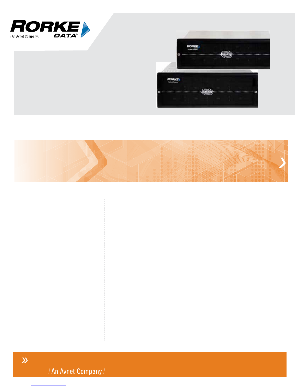
Galaxy GHDX4 RAID iSCSI-SAS/SATA Installation+Hardware Reference Manual
2
Hard Drive Installation.............................................................................................38
Hard Drive Installation Prerequisites................................................................................38
Drive Installation...............................................................................................................39
Drive Tray Installation.......................................................................................................40
Chapter 3 Subsystem Monitoring...............................................................43
Overview..................................................................................................................43
Status-indicating LEDs............................................................................................44
LCD Keypad Panel...........................................................................................................44
Drive Tray LEDs...............................................................................................................45
Controller Module LEDs ...................................................................................................46
How to Use the Restore Default Button?..........................................................................48
Why restore defaults? ......................................................................................................48
Ethernet Port LEDs ..........................................................................................................49
PSU LEDs........................................................................................................................51
Cooling Module LEDs.......................................................................................................51
Audible Alarm..........................................................................................................52
Failed Devices..................................................................................................................53
I2C ....................................................................................................................................53
Chapter 4 Subsystem Connection and Operation.....................................54
Connection Overview ..............................................................................................54
Cabling.............................................................................................................................54
Network Topologies..........................................................................................................55
Points of Failure ...............................................................................................................55
Host Connection Topologies ............................................................................................55
Sample Topology – Single-controller with Fault-tolerant Paths........................................58
Sample Topology – Single-Controller with Trunks............................................................59
Sample Topology – High Availability IP SAN with Redundant RAID Controllers..............60
iSCSI Topology and Host LUN Mapping:.........................................................................62
Expansion Links ......................................................................................................63
Single-controller RAID to single-controller JBOD.............................................................63
Dual-controller RAID to dual-controller JBOD. .................................................................64
Enclosure ID and Other Concerns....................................................................................65
Powering On............................................................................................................66
Check List.........................................................................................................................67
Power-On Procedure........................................................................................................67
Power-On Enclosure........................................................................................................68
Power-On Status Check...................................................................................................68
Power Off Procedure...............................................................................................69
Chapter 5 Subsystem Maintenance and Upgrading...............................70
Overview..................................................................................................................70
Maintenance.....................................................................................................................70
General Notes on Component Replacement....................................................................70
Replacing a Controller Module................................................................................72
Overview ..........................................................................................................................72
Notes on Controller Maintenance.....................................................................................72
Removing the Controller Module......................................................................................72
Replacing the Controller Module......................................................................................74
Replacing or Upgrading Memory Modules..............................................................75
Memory Module Installation Overview..............................................................................75
Selecting Memory Modules..............................................................................................75
DIMM Module Installation.................................................................................................76
Replacing a Faulty BBU ..........................................................................................77
Fault Conditions: ..............................................................................................................77
BBU Warnings and Precautions.......................................................................................77
Replacing a Faulty BBU...................................................................................................78
Replacing a Faulty Flash Backup Module (FBM) .............................................................79
Replacing a Faulty PSU ..........................................................................................80
Notes on PSU Module Maintenance ................................................................................80
Replacing the PSU Module..............................................................................................81