Rosco LitePad Loop User manual

LitePad Loop™
User’s Manual
Model 1008

2

3
Languages
English........................................................
Spanish....................................................
German.....................................................
French.......................................................
Japanese................................................
Italian....................................................
Pages 4 - 27
Pages 28 - 51
Pages 52 - 75
Pages 76 - 99
Pages 100 - 123
Pages 124 - 147

4
In the Box........................................................
In the Pro Kit....................................................
Parts Diagram.............................................
Troubleshooting..............................................
CE...................................................................
RoHS..............................................................
Warranty.........................................................
Installing the Safety Thumb Screw..................
Attaching the Safety Cord..............................
AA Battery Holder............................................
Color Filters.....................................................
4” L-Bracket....................................................
8” Rods............................................................
Light Stand Plate.............................................
Using AC Mains Power....................................
Using Battery Power.......................................
Dimming Control.............................................
Attaching Loop to the Camera........................
Adjusting Loop Position...........................
Support
Safety Connections
Using Optional Accessories
Powering Up
Setting Up Your Loop
Your LitePad Loop™
24
25
26
27
G
Parts and Accessories List........................21, 22
Technical Data...................................................23
F
19
20
E
14
15
16
17
18
D
12
13
13
C
9
10, 11
B
5
6
7, 8
A
Table of Contents - English

5
A
In the Box
Your LitePad Loop
[1] - LitePad Loop
[2] - Mounting Assembly
[3] - AC Transformer and Blades
[4] - 10’ Extension Cord
[5] - Safety Cord
[6] - Safety Thumb Screw
[7] - Allen Key
[8] - Storage Pouch
[2]
[3] [4]
[5]
[7]
[6]
[8]
[1]

6
A
In the Pro Kit
Your LitePad Loop
[1]
[2]
[1] - LitePad Loop
[2] - Mounting Assembly
[3] - AA Battery Bracket
[4] - Battery Mounting Adapter
[5] - Safety Cord
[6] - Allen Key
[7] - 8” Rods
[3]
[4]
[9]
[8]
[6]
[5]
[7]
[8] - Light Stand Plate
[9] - Safety Thumb Screw
[10] - Color Filter Pack (8 Filters)
[11] - AC Transformer and Blades
[12] - 10’ Extension Cord
[13] - AA Battery Holder
[14] - Single Fader Dimmer
[10]
[11]
[12] [13] [14]
7
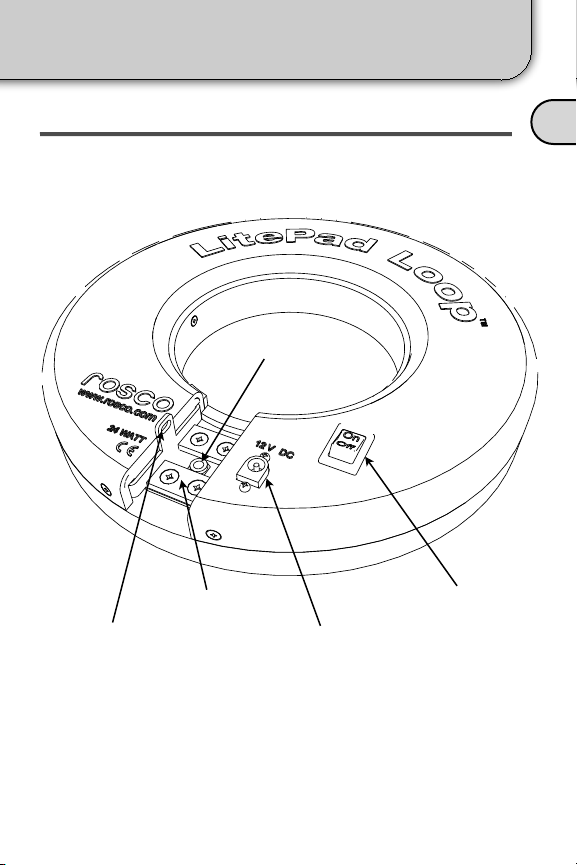
LITEPAD LOOP A
Parts Diagram
Your LitePad Loop
Safety Screw
Nut [2]
Magnets [3] Power Switch [5]
Safety Cord Hole [1] Power Connector [4]

8
Mag. Plate
Wing Nut [10]
Safety Cord Hole [14]
Sled [8]
(2) 4” Rods [9]
Main Block [7]
Mag. Plate [13]
Thumb Screws [6] 2” L-Bracket [12]
Knob [11]
ALITEPAD MOUNTING ASSEMBLY
Parts Diagram
Your LitePad Loop
9
1) Attach the Mounting Assembly to your camera by
screwing the Knob [11] into the threaded socket in the
bottom of the camera. Align the camera so the lens is
parallel with the L-Bracket [12]. Tighten the Knob to
ensure the camera will not move during use.
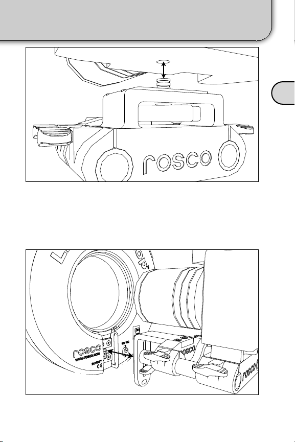
B
Attaching Loop to the Camera
Setting Up Your Loop
2) Attach the Loop to the L-Bracket [12] by bringing the
Magnets [3] into contact with the Magnet Plate [13].

10
Loosen the thumb screw and slide the Loop up or down.
B
The camera lens should be centered within the LitePad
Loop. To adjust the Loop vertically, loosen the Mag. Plate
Thumb Screw [10] and move the Loop up or down until
the camera lens is centered then tighten securely.
VERTICAL POSITION
Adjusting Loop Position
Setting Up Your Loop
Center the camera lens vertically.
This manual suits for next models
1
Table of contents
Languages:
Other Rosco Camera Accessories manuals


Popular Camera Accessories manuals by other brands

Viltrox
Viltrox EF-NEX Mount instructions

Calumet
Calumet 7100 Series CK7114 operating instructions

Ropox
Ropox 4Single Series User manual and installation instructions

Cambo
Cambo Wide DS Digital Series Main operating instructions

Samsung
Samsung SHG-120 Specification sheet

Ryobi
Ryobi BPL-1820 Owner's operating manual


