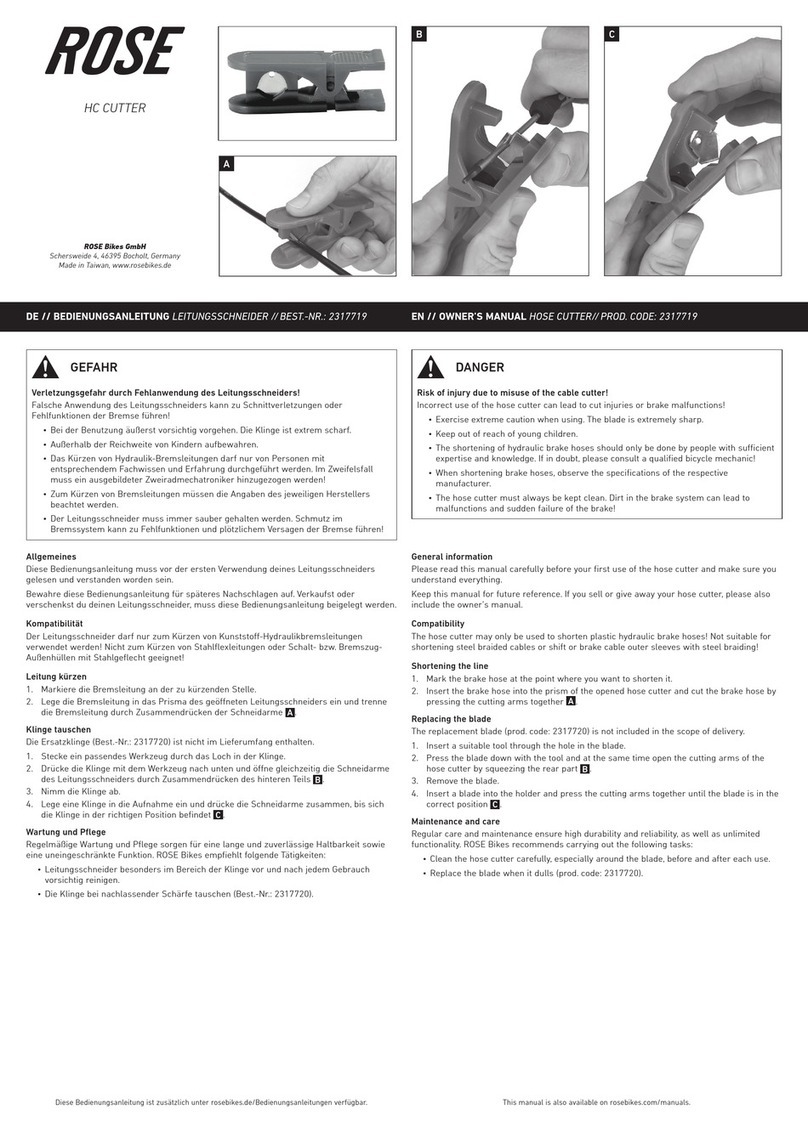
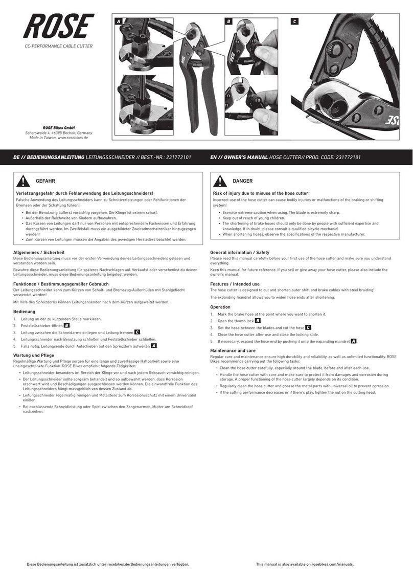
Rose electronics BesCutter G Series User manual

Rose Graphix LLC DBA BesCutter.Com, 5490 Lee St, Lehigh Acres, FL 33971 888-525-2897
User Manual
(Version: V6.15)
BesCutter
Fiber Laser Cutting
M
achine

1. Preface
Thank you for purchasing the G series laser cutting machine from Rose Graphix LLC. If this is
your first time to use this machine, please read the manual carefully before using the machine. The
content labeled "dangerous", "warning" and "attention" must be pay attention to specially to ensure
the safety of your and surrounding personnel, and proper use of this equipment.
"Dangerous": If you do not follow the correct operation, it may immediately lead to serious injury
or even life-threatening.
"Warning": If you do not follow the correct operation, it may immediately lead to serious injury or
even life-threatening.
"Attention": If you do not follow the correct operation, it may immediately lead to serious injury or
damage to the equipment.
2. Product overview
2.1 Summary
Adopting large power, high performance fiber laser with international advanced technology and
Cypcut high-grade CNC system, equipped with imported original AC servo motor and some high
efficient transmission mechanism, such as, German original gear and rack, imported high-precision
linear guide, the G series laser cutting machine is stable and reliable, good dynamic performance, with
a strong load capacity performance. Having high speed, high precision, high efficiency, high cost
performance, etc, this is high-tech products integrated with laser cutting, precision machinery,
numerical control technology and other disciplines. Users must read the manual carefully before the G
series laser cutting machine is used. If there is any problem in using process, please contact us in time,
we will give you a satisfactory answer in the shortest time.
Please check the manual in accessory box when it is opened. If the manual is not complete, please
contact us in time.

2.2 Product characteristics and appearance
Figure: The machine appearance
Note: All the pictures in this manual are for reference only. (Do not include the products special instructions). The product provided
the user shall be prevails
a. Beams cast having double column framework layout and bed welded being large cross section,
the machine is high at rigidity, stability and shock resistance.
b. Precision linear guide, gear and rack imported being transmission components, the machine is
higher at precision and speed, positioning accuracy is ± 0.03mm/m, and repetitive positioning accuracy
is ± 0.02 mm, maximum speed (no-load) is 80m/min.
c. The Cypcut control system is adopted that can satisfy the processing of various kinds of board.
The AC servo motor is small inertia and better at dynamic performance.
d. Revolution being reduced by the reducer (its back lash is less than 5 arcmin), the servo motor
drives the moving components to assure output power at low speed.
e. The laser and main machine are installed together, which ensures the stability of light path.
f. IPC equipping with CAD/CAM, so it is convenient to drawing and program in cutting, which
maximize the conservation of raw materials.
g. Cutting chip falling into the scrap car from funnel, so it is convenient to clean up the chip regularly
by operators.
h. Rack and guide way of X axis and Y axis are dustproof that are covered by protection cover to

prolong the service life. Gear and rack of X axis and Y axis are regularly lubricated by central lubrication
devices; linear guide way of X axis and Y axis are lubricated by manual regular.
i. Z axis motor is controlled by capacitive sensor to driven cutting head that moves up and down,
which ensure the distance between nozzle and the plate cut to be constant to ensure the cutting quality.
Drawer-style lens base is adopted in cutting head, so it is extremely convenient to replace or clean the
lens. According to the material and thickness of the plate cut, focus position can be adjusted up and
down to ensure cutting quality.
j. Travel limit switch are used to control motion stroke in X, Y and Z axis, at the same time, elastic
cushion pads are used also at limit position for the movement safety.
k. Closed optical path is adopted to ensure the service life of the lens.
l. Equipped with automatic focusing system, the laser head is prompting and accuracy to move.
m. Components imported are adopted in the gas path system. Three different kinds gas can be filled
simultaneously and chosen freely. The pneumatic system is designed to withstanding high pressure
and to ensure system stability; the nitrogen pressure may be 3.0 Mpa, in the cutting of stainless steel
plate. All these improve the reliability and cutting quality.
n. Operation platform possess elegant appearance, operating the machine is as happy as you do at
ATM.
2.3 Main use and scope of application
Using medium - power fiber laser, this series of laser cutting machine is mainly used to cut ordinary
carbon steel plate, stainless steel plate, galvanized sheet and other materials. It has the advantages of
high precision, high efficiency, and high cost performance and so on.
Note: if the power of the laser chosen is different, the range of the cutting material may be
different.
2.4 Environmental conditions
a. Standard power supply: Three-phase five wire, 380V 50Hz
b. Total power of main machine is not greater than15KVA;
c. Power of laser and cooling-water machine is not greater than 5KVA;
d. Power quality: three phase unbalance is less than 2.5%, line voltage fluctuation is less than 5%.

e. The machine must be grounded, grounding pile on machine side and connecting wire, to connect
machine to a power wire is also allowed, and the grounding resistance should be less than 4 ohm.
f. Site environment: good ventilation conditions, no dust, no corrosion, and no pollution.
g. Installation foundation: There is no larger vibration source surrounding machine; there is anti
vibration groove surrounding.
h. laser working temperature is lower than 20℃.( See the instructions of the laser)
i. Chiller is the special equipment providing circulating cooling water to laser and lenses. Water flow
should maintain above 12L/ min; circulating cooling water should be high quality pure water or distilled
water.
j. For fire prevention, appropriate fire extinguishers should be configured and fire channel is reserved at
processing sites.
k. The distance from machine left side to the workshop wall and the distance from machine backside to
the workshop wall should be larger than 1.2m; the distance from laser backside to the workshop wall
should be larger than 1.5m. Chillers and air compressor can be placed outdoor, but the distance from
the laser should be less than 5M.
l. Control unit, servo unit, display and control panel should avoid being subjected to electromagnetic
waves interference, such as electric arc welding and electrical discharge machining machine, which will
affect the machine normal work.
2.5 The influence on environment and power requirement
An optical fiber laser generator is used in this machine; waste gas will be generated during cutting,
so is necessary to switch on the exhausting device in cutting process.
The fiber laser generator belongs to the fourth category laser products. Light beam emitted, or
reflection and diffuse light from mirror may cause damage to the human body (especially the eyes),
personnel presence should pay attention to the protection, should also prevent the occurrence of fire.
Being high energy consumption equipment, the laser cutting machine needs total power about:
three phase 380V 50Hz, 12KVA (500W continuous type laser and chillers. If laser selected is different,
the power needed will be different also).
2.6 Machine structure and working principle

G Series CNC laser cutting machine is mainly composed of the main machine, control systems,
laser, chiller and exhaust fan, etc. Except for exhaust fan and chiller, others have there’s own manual.
This manual mainly introduces the structure of main machine and electrical control system; the rest
parts can be referred in their specification.
The main machine is the most important component of the laser cutting machine; it is guarantee to
achieve cutting capabilities and assure cutting accuracy. Main machine consists of the bed, laser
generator, beam section, Z-axis device, table, auxiliary (protection cover, pneumatic system and
cooling system, lubrication system), console, and so on. Details see section 2.6.2.
Electrical control system that consists of CNC systems and low-voltage electrical system is an
important part to achieve various type graphics running track.
CypCut CNC system, based on the WINDOWS system operating platform, is used on this
machine. Containing 32-bit microprocessor, internet communication interfaces, operation reliable, and
the system has characteristics of fast interpolation operation, convenient operation, good dynamic
performance, strong load capacity and so on.
The low voltage electrical apparatus control system, located within the cabinet, is interface of the
whole electrical control system. All the components used in electrical system are produced by
well-known manufacturers, which ensure the machine’s stable and responsive in operation. Driving
motor is AC servo motor that drive the X-axis (beam), Y-axis (slide), which have good accelerate
performance, quick response; maximum position speed is up to 80m / min. Z axis, laser cutting head,
being feeding axis, is driven by AC motor to move up and down; cutting head is good at dynamic
response and can be servo controlled as well as NC controlled.
Other auxiliary including large and small chiller, air exhaust system, is introduced in detail at
section 2.6.2.
2.6.1 The overall structure and working principle, characteristics
The main machine is the most important component of the laser cutting machine; the cutting
capabilities and cutting accuracy is achieved by this part. Main machine consist of the bed (X axis),
beam (Y axis), Z axis, exchange table (optional), table, gas path, water path and other components,
etc.

2.6.2 The structure, function, and working principle of main components or functional
units
2.6.2.1 Bed
Being a rectangle frame structure that is welded by high strength steel, bed is annealed to
eliminate internal stress after welding and is vibrating treated after roughing. There is also vibration
effectiveness after semi-finishing. Because of stress relief more thoroughly, so the bed deformation is
small, and the precision is good for a long time.
2.6.2.2 Beam
Beam is cast from high-strength aluminum. After solution treatment and artificial, it is machined to
ensure the accuracy and service life. The processing flow include roughing, VSR, semi-finished, VSR,
finishing.
Beam is installed on the support rail of bed (there are linear guide rails and flat rail); it can move
reciprocating in the X-axis direction. The movement is achieved by rack and pinion transmission, in
which 2 racks are fixed on the bed and 2 pinions are driven by 2 serve motor directly to synchronous
rotate; pinion translation makes the beam move in the X-axis direction. High-quality linear guides are
mounted in beams system. Cutting head, fixing on slide, is driven by servo motor through reducer and
move reciprocating in the Y-axis direction. There are the soft limit switches control stroke, and
elasticity buffer at limit position to ensure that the system is running security. Retractable organ type
shield located between the beams and cross slide ensure the rack and linear rail runs in fully enclosed
environment, to unaffected by the external environment.
2.6.2.3 Z-axis device
Z-axis device drives the cutting head to move up or down. Cutting head is located on Z-axis slide,
its ball screw is driven by servo motor controlled by CNC system. The travel stroke of Z axis is 120mm;
there are limit switch at upper and lower ends to control the Z axis stroke, while there are elastic
cushion at both ends to ensure the safety of movement. Ball screws and linear guides adopted are all
high-quality products to ensure the transmission accuracy.
Z-axis both can do its individual interpolation motion, being a CNC axis, and can do association
motion with X, Y-axis. It can be switched to follow control by changing electronic control to meet the
needs of different situations also. Since the Z-axis follow is controlled by the numerical control system,
thus relatively moving accuracy is higher, stability is better, so as to ensure the cutting quality. Having
sealed and elastic buffer, the cutting head has longer service life.

After the distance from the nozzle to plate surface is detected by the capacitive sensor installed in
the cutting head, the signal is fed back to the control system, then the cutting head, driven by Z axis
motor, moves up and down to assure the distance between the nozzle to plate unchanged and to
ensure effectively cutting quality. There is adjusting device in cutting head, the position of the focus
can be adjusted, and according to the material and thickness of the plate cut, thereby good cutting
surface can be obtained.
Nozzle is one of wearing; some nozzles having different aperture should be conserved by users to
facilitate replacement.
The guides and lead screw lubrication oil nozzle are set up in Z-axis, these nozzle should be
regularly oiled.
2.6.2.4 Electrical control
The electrical control system of G series CNC laser cutting machine is mainly composed of
numerical control system, servo systems and low-voltage electrical system. CypCut CNC system,
which is a PC CNC system based WINDOWS, is adopted by the laser cutting machine. This CNC
system has the characteristic with interpolation operation fast, easy to operate; Servo system includes
Fuji AC servo motor and driver, reliable, good dynamic performance, with bigger load capability.

Figure: CNC operator interface
a) Easy to operation
There are six function soft keys and eight operational soft keys in this machine, operational soft
keys have different functions in different operation mode, thereby the operating button are reduced and
the operation panel is simplified. There are menu display functions in any mode, so operation is
intuitive.
The machine has HELP system, the operator, even if who are not familiar with the instructions, can
operate machine base on the prompt of the CNC system.
b) Special laser power control function
According to the speed / power function curve set by operator, the optimal laser cutting power can
be obtained by adjusting precisely laser power at different speeds when components are acceleration
or deceleration.
c) Strong processing function
The machine has a variety of processing and auxiliary function instruction; complex graphics can
be obtained by the instruction editor.
d) high-precision machining
Having a good dynamic electromechanical drive performance, the machine is good follow
performance and high precision in the process.
e) Graphic display
There is graphic display and dynamic graphics simulate trace display function for parts program
edited. processing is more intuitive, easy monitoring and control.

Figure: Graphic display
f) Various alarm functions
Having a self-test alarm system and automatic protection function, this CNC system also can do
alarm display and automatic protection for external conditions.

Figure: Alarm functions
g) The electrical control system can be divided into CypCut CNC systems, machine control panel,
low voltage electrical systems, motors and machine electrical, according to its mounting position.
h) CypCut CNC system
Belonging to high-end system, CypCut CNC system is special CNC laser system for CNC machine
tools. The integrated structure; central control and display are adopted by this system, so the operating
unit possesses structure compact and is mounted on the operating table.
The system is PC CNC system WINDOWS-based, hard disk is 60G, the part program memory is
400KB, Internet communication interface, three axes and one spindle can be controlled. A good
man-machine interface is provided by display operating unit. Various operational information, keyboard
and function keys are all displayed in17-inch TFT LCD color LCD, which is used to input information
and operate machine.
i) Height system operator panel
The system operator panel is located in the top right corner of the left electrical control cabinet.

j) Low-voltage electrical system
Low-voltage electrical system, located inside the machine cabinet, is the interface part of the whole
electrical control. The power supply, relays, circuit breakers, contactors, servo drive system for
electrical control system are all installed in the cabinet inside. The main power switch is located in the
left side of the cabinet.
k) Motors and machine electrical
Driving the machine axes, AC servo motor are connected with the corresponding axis, namely
X-axis drives beam, Y-axis drives slide and Z-axis drives cutting head. Machine electrical includes the
origin switch of each moving axis, pneumatic solenoid valve, pressure switch etc.
2.6.3 Mechanical and electrical contact between each unit structure, fault alarm system
Figure: Unit structure contact diagram
Chiller Stable power Laser
Gas CNC
Air-drying machine
Machine
Compressor

The above figure shows the close relationship between the various components. Stable power
provides energy for the chiller, laser and main machine; chiller cools the laser and the main machine;
other portions provide effective measures to serve the main machine.
Each electrical circuit is provided over-current protection by the air switch; there are mechanical
limit location, electrical soft limit and hard limit protection in each axis. Electrical hardware limit can cut
off the power and stop the machine running and alarm; mechanical limit ensure the safety of equipment
and operator in case of any accident. The system itself also has a motor overload and over-temperature
protection. Alarm list see section 5, 6, and Cypcut alarm system user manual.
2.6.4 The function structure and working principle, operating characteristics of auxiliary
devices
2.6.4.1 Gas path system
The gas path in this laser cutting machine is divided two parts, one part supply cutting gas to the
cutting head, cutting gas include clean and dry air, high purity oxygen and high purity nitrogen, another
part supply the auxiliary gas, being clean and dry compressed air gas for the use of clamping table
cylinders.
Entering into the control cabinet through the gas tank and the cold dryer, the gas coming out from
the compressor turn into a clean, dry gas by a sophisticated air-handling system and is divided into two
parts, one part is the cutting gas, another part is used by gas cylinders. There’s pressure can be
adjusted by a corresponding regulating valve.
Cutting gas is included three gases, they are compress air, oxygen and nitrogen, and these three
kinds of gas can be selected according to different requirements. Oxygen is mainly used to cut ordinary
carbon steel; nitrogen is mainly used to cut stainless steel and alloy steel, compress air is mainly used
to cut metal plate that cutting surface quality is not very high. Different cutting gas is used to cut
different materials. The pressure sensor is applied in the cutting gas system also, to stop working in
time when gas pressure is not high enough to avoid that the part cut is scrapped. Its pressure value can
be set by adjusting the screw top on pressure sensor; the pressure value of compressed air and
oxygen, being used to cut, can also be adjusted by the process ratio control valves controlled by
program.
The function of compressed air in the machine includes the following. 1, drive clamping cylinder
and clamp the table to ensure that the table is motionless in cutting process, cutting is smooth. 2, assist
feeding. 3, auxiliary cutting, remove dust, clean cutting surface.

2.6.4.2 Water path system
Water path system also consists of two parts, some cooling water coming from the chiller enters
the laser to cool the laser through the radiator inside, and than return to chiller; another part is used to
cool the optical path and cutting head.
2.6.4.3 Oil lubrication system
The oil lubrication system is composted of automatic pumps and piping. Pump interval is 4 hours
(can be changed); pump oil time is 10 seconds (can be changed). When the oil pump’s oil level is too
low, the pump will alarm, and sound an alarm, to add the oil into pump is needed this moment.
3 Safety instructions and precautions
3.1 Summary
Before operating the machine and routine maintenance, the operator must read this chapter
carefully to understand the safety measures and requirements of the machine and comply with the
relevant safety precautions.
3.2 Involved Safety Standards
Laser processing equipment and operations shall comply with following two national standards,
GB7247-87 the radiation safety of the laser products, equipment classification, requirements and user's
guide, GB10320-88 The electrical safety of laser equipment and facilities.
3.3 Safety warning labels and instructions
See 5.3 operation guide safety, security protection, safety signs and instructions while before
machine is used or is using.
3.4 Security warning
Specify security administrator, determine his responsibility, and train safe operation and safety for
laser processing operator.
Specify laser safety management area, set up warning signs at entrances and exits in
management area, including: power, laser types of laser processing machines, prohibit outsiders
entering, eye protection and safety manager names, etc.

The operator of the machine cannot go on duty until he go through specialized training, up to a
certain level, and is permitted by the security administrator.
3.5 Laser Safety Notices
Laser is very harmful to the eyes and skin of human; any part of human body can be burned under
laser irradiation, avoid exposing any part of your body to the light path of the equipment to avoid
damage caused by misuse.
3.5.1 Eyes and skin protection
CO2, YAG lasers or fiber lasers is usually used in laser processing. Different types of laser, the
damage to the human body is different. YAG laser and fiber laser may damage the retina of the eye, as
the high wavelength YAG laser and fiber laser are transmittance to the eyes, so the dangers is greater.
CO2 laser may burn the eye cornea. These two laser irradiation are likely to cause cataracts and skin
burns danger to the eye, therefore, appropriate protective measures mast be adopted when laser is
adjusted, according to different laser.
3.5.2 Fire Protection
Oxygen is used generally, and there will be spark splash in cutting process, which is easy to lead
to a fire hazard. There are no flammable and explosive materials in work area, appropriate preventive
facilities should be equipped also.
3.6 Electrical Safety
Do not touch any switch with wet hands to avoid electric shock. There are some sites affixed
lightning signs in the machine, where high-voltage electrical appliances or electrical components are
located. Approaching to these sites or repairing, operator should be careful to avoid electric shock.
These sides include, servo motor cover, the connecting box behind columns, machine transformer
cabinets, electric doors, etc.
Read the machine manual carefully to be familiar with various functions and the operation methods
of corresponding keys.
Do not open the electric door casually; prohibit changing unauthorized parameters set already,
potentiometers and timers. If these are needed to change, the change must be done by professionals
who is trained by the manufacturer and accredited, and parameter values before changing must be
record also. if necessary the original state can be restored.

Do not touch the charged components in the electrical cabinet, such as, CNC equipment, servo
devices, transformers, fans, and so on, while power is on.
3.7 Material Safety Notices
The focusing lens and other optical instruments are manufactured using chemical vapor
deposition method. When the temperature is above the point of combustion, these materials will
generate toxic Se vapor that is highly toxic substance. The lens has been coated with radioactive
material thorium compound film to improve the transmittance, so lens need to send to the professional
manufacturers (or manufacturer) if lens damage, to avoid damage to the environment.
3.8 Machine protective measures
Specify security administrator, determine his responsibility, and train safe operation and safety for
laser processing operator.
Specify laser safety management area, set up warning signs at entrances and exits in
management area, including: power, laser types of laser processing machines, prohibit outsiders
entering, pay attention to eye protection and safety manager names, etc.
When the machine is not used, pull out the switch key, kept it by the designated person to avoid
harm caused by misuse. Exhaust smoke gas and waste gas produced in laser processing should be
Warning
Do not touch terminals within 5 minutes of
power off. Because high voltage will remain
between power lines, so do not touch the terminal
immediately to avoid electrical shock.

discharged to outside through the pipe, all cylinders should be placed neatly stable.
3.9 Operator common knowledge
The operator of the machine cannot go on duty until he go through specialized training, up to a
certain level, and is permitted by the security administrator.
Operators or personnel near laser should wear appropriate laser safety glasses during working.
There will be good indoor lighting at protective region, in order to ensure the convenient operation.
In order to protect the operator, a process chamber or protective screen must be set. There should
be security devices to protect laser diffusion and protect the operator in process chamber. The laser
shutter should be turn off when process chamber door is opened.
4 Installation and debugging
4.1 Delivery check
4.1.1 Unpacking Caution
Please open the wood box according to the prompts outside of the box, to avoid damage the
equipment, if the machine is packed in wood cases. Main machine and other equipment are packed
using protective film, it is not allowed to cut protective film using sharp object to avoid that surface is
scratched and that electrical line or pipeline is damaged. The damage caused by customers
themselves is not covered under warranty.
4.1.2 Check contents
After opening the package, please confirm whether it is the product you buy.
Check whether there is any damage in transport.
Comparing with the list, you check whether the components are complete or not, is there any
damage.
In the condition that product model does not agree with contract, the lack of attachment or
transport damage is found, etc., please contact us.
4.2 Installation methods and precautions

4.2.1 Lifting and transportation machines
a. Equipped with lifting holes, the machine can be hoisted. lifting hole location shown as below:
Figure: Lifting hole
b. the machines can also be transported by forklift, truck bits shown as below:
Figure: forklift bit
Note: When using forklifts, forklift fork into the side of the machine is not a tank located on the side chain, the chain of tanks into the
Lifting hole

side of the fork is not allowed, to avoid damage to tanks, chain and internal optical fiber cables.
4.2.2 Chiller installation
--- Flow: Min 3.5L / min, maximum 13L / min.
--- Cooling capacity: 14483Btu / h.
--- Water pressure difference between inlet and outlet: Minimum 3kgf / cm2.
--- Temperature controlling capacity: ± 10 ° or less.
--- Cooling water: high quality, pure water distilled or deionized water.
--- Valves and pipes: all the valves material is stainless steel and pipe are high-pressure hose;
galvanized material is not allowed to use, pipe joint are fixed using stainless steel clamp.
--- External laser water pipes is the pressure rubber pipe, plastic (PVC) pipe, its internal diameter
being 6mm, external diameter being more than 8mm. Stainless steel, and brass pipe are also available.
If the chiller pipe length is more than 10 meters, to increase the pipe diameter is needed to assure the
pressure difference lasers needed. For different lasers, connecting pipe dimensions are also
differences.
--- Cooling water pipes of optical path: PU pipe pressure being not less than 6kgf / cm2, pay
attention to the sealing in pipe joints.
--- Filter hole diameter is 100um, so it is better for pipe material to be transparent plastic, the filter
used between the chiller and laser must be the standards filter requested by manufacturers.
a. Mounting conditions
Chiller should be placed firmly and it is not too near from the wall, the installation space must be
larger enough to ventilate to improve chiller cooling.
b. Machine check
Check whether the Joint in water path system loose, check whether the filter device in chiller
filtration are tightened.
c. Installation method
Connect water pipeline to the corresponding connector of the unit, and note the direction of inlet
and outlet, connect the inlet and outlet of chiller to the inlet and outlet of laser respectively based on the
signs of chiller. Make sure pipes are connected correctly and there is no garbage and foreign matter
outer pipe. As shown below:

Figure: water inlet and outlet
d. Water quality standards
Open the inlet valve, add water to the tank, water level should be at the appropriate height marked
to prevent water overflow from the tank. Tap water are not generally allowed to use, high-quality pure
water, distilled or deionized water can be used, otherwise water scale will be produced in chiller
refrigerator and laser radiator to cause component damage. Prohibit adding any corrosive liquids.
e. Debug the machine
Put on power, check and sure that the single-phase three-wire electrical are connected correctly
within the unit, turn on the chiller and wait for water temperature inside the chiller to rise suitable
temperature.
f. starting step
Before booting, make sure pipes of chiller are connected correctly, and then start the machine and
check whether there is leaking pipe joints.
g. Note:
(1) When the water temperature reaches the control temperature, chiller will control automatically
constant temperature, and water pump still run now.
(2) The laser cannot be started until that the cooling water temperature, pressure difference
between inlet and outlet reached the required value of the laser.
Water-cooled laser head joints
Water
-
cooled laser
Table of contents
Other Rose electronics Cutter manuals