Rosen Aviation 0601-001 User manual

Rosen Aviation
Document Number: 100173 Revision: G
Date: 17 April, 2007
Template: 4.2.3-6-FM; Revision A; 16 May, 2005 Page 1 of 10
Technical Manual
DVD Player 0601-001
ELECTRONIC
REVISION
CONTROLLED

Rosen Aviation
Document Number: 100173 Revision: G
Date: 17 April, 2007
Template: 4.2.3-6-FM; Revision A; 16 May, 2005 Page 2 of 10
1. TECHNICAL SPECIFICATIONS AND REFERENCES ......................................................3
1.1. Pinout Information.........................................................................................................3
1.2. Connection Options ......................................................................................................3
1.3. Control Inputs ...............................................................................................................4
1.4. Audio/Video Outputs.....................................................................................................4
2. ROSEN DVD PLAYER INDICATORS, CONTROLS AND CONNECTIONS ......................5
2.1. Front Case Indicators and Controls ..............................................................................5
2.2. Multiple DVD Control Setup ..........................................................................................6
2.2.1. IR Control ............................................................................................................................6
3. RS-485 INFORMATION......................................................................................................6
3.2. Communication Protocol...............................................................................................7
3.3. Packet Format ..............................................................................................................7
3.4. Packet Timing ...............................................................................................................7
3.5. Wiring............................................................................................................................7
3.6. Packet Format Descriptions for Single-Disc DVD Control Commands .........................7
3.7. DVD General Status Request .......................................................................................9
3.8. DVD Addressing ...........................................................................................................9
3.9. Network Setup Ping Address ........................................................................................9
4. TROUBLESHOOTING......................................................................................................10
4.1. Disc Removal—Use of disc with paper label NOT recommended ..............................10
5. REVISION HISTORY ........................................................................................................10

Rosen Aviation
Document Number: 100173 Revision: G
Date: 17 April, 2007
Template: 4.2.3-6-FM; Revision A; 16 May, 2005 Page 3 of 10
1. TECHNICAL SPECIFICATIONS AND REFERENCES
1.1. Pinout Information
The DVD Outline and Installation drawing is shipped with the
packaging contents. If you are unable to locate the drawing, use
the Rosen Aviation website to download a copy.
www.rosenaviation.com
Click on the Support & Documentation tab. Select Technical
Drawings & Pinouts, Source Equipment, and then choose the DVD
Player drawing link.
1.2. Connection Options
It is possible to connect an auxiliary audio/video source and switch between that source and this
DVD audio video by connecting to the switched audio/video outputs.
Note: The switched audio/video outputs can be controlled with the select switch input or
through RS-485, RS-232, or infrared (IR) remote control.
DVD Player
DVD Output
Inputs
Aux Input
RS-232
IR Control
Pause
RS-485
Select Switch
Switched
Audio/Video
Outputs

Rosen Aviation
Document Number: 100173 Revision: G
Date: 17 April, 2007
Template: 4.2.3-6-FM; Revision A; 16 May, 2005 Page 4 of 10
1.3. Control Inputs
For Controller information, access www.rosenaviation.com.
Click on Accessories and select External Controllers. Scroll
through the list to find the desired product.
RS-485: Rosen DVD can be controlled with RS-485. For specifications see
Section 3, RS-485 Information.
RS-232: Rosen DVD can also be controlled with RS-232. For specifications please contact
Rosen Aviation technical support at 541.342.3802.
IR Remote: Rosen DVD can be controlled using one of several of Rosen Aviation’s pre-
programmed remote controls. Visit the Rosen Aviation website for details.
Cabin Briefing Pause: pauses the DVD player for briefings when the cabin briefing pause input
is enabled (low).
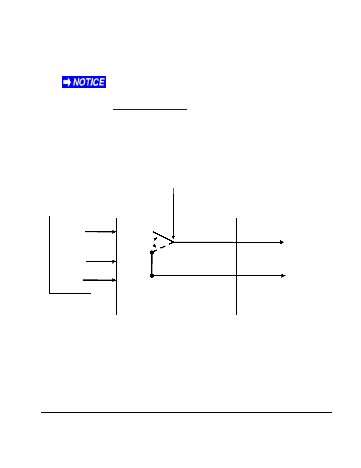
Optional Cabin Briefing Pause: The switched video output can be set to pause the
DVD player and automatically switch to auxiliary video input during cabin briefings. To
enable this feature, press the following button sequence (with no disc in the player):
1. ◄◄, ►►, Λ,V,◄◄, ►►, Λ, V, Λ, Λ, Λ
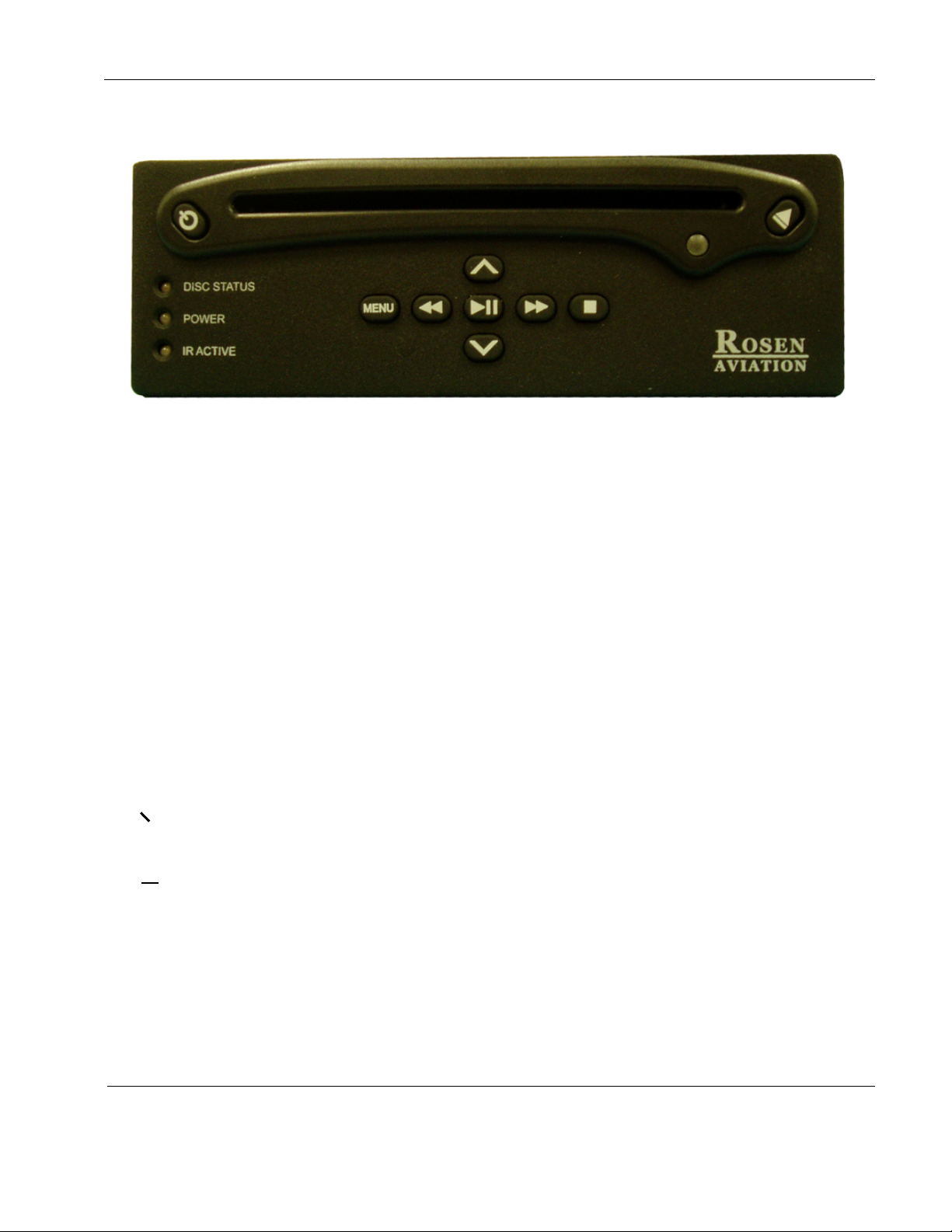
2. While watching the red DVD LED, press the ▲eject button one time.
a. If the DVD LED light blinks twice, then the optional feature is active.
b. If the DVD LED light blinks once, cabin brief / pause is in default mode.
Note: Enabling or disabling this feature can be done one time per button
sequence. To change the feature again, re-enter the button sequence.
Select Switch: Select switch is a momentary switch that can be used to switch between DVD
and auxiliary audio/video sources when an auxiliary source is connected. Pressing select switch
changes the source from DVD player to auxiliary source (or vice-versa).
1.4. Audio/Video Outputs
DVD Video Out: 1V peak-to-peak (p-p), 75 ohms
DVD Audio Out: 1V RMS (0db FS), 600 ohms
Auxiliary Video In: 1V p-p, 75 ohms
Auxiliary Audio Line In: 1V RMS nominal, 4.7k ohms; Max Input Voltage 5.8V p-p
Switched Video Out: 1V p-p, 75 ohms; unity gain from auxiliary video input
Switched Audio Out: Unity gain from auxiliary audio input is 600 ohms
Note: While there is an accepted standard of 1V p-p for video signals, the audio output
level from different devices can vary considerably. If there is a large difference in audio
level when switching between the DVD player and the auxiliary input, try adjusting the
audio output level of the auxiliary device. If there is no output adjustment and the audio
level from the auxiliary device is higher than the DVD player audio, then use a
potentiometer, step-down transformer, or resistors to attenuate the auxiliary audio level.
If the auxiliary audio level is lower than the DVD player audio, then install a line-level
amplifier or step-up transformer to boost the signal.

Rosen Aviation
Document Number: 100173 Revision: G
Date: 17 April, 2007
Template: 4.2.3-6-FM; Revision A; 16 May, 2005 Page 5 of 10
2. ROSEN DVD PLAYER INDICATORS, CONTROLS AND CONNECTIONS
Figure 1 Rosen DVD Player front case showing LEDs and control buttons
2.1. Front Case Indicators and Controls
Menu: If a disc is inserted, pressing Menu will access the disc menu. If no disc is inserted,
pressing Menu will access the DVD player’s setup menu.
◄◄: Press this control to navigate left in a menu. If held in while a DVD is playing, this button
will serve as a “rewind” for the DVD. Continue to hold the button and different rewind speed
options become available.
►►: Press this control to navigate right in a menu. If held in while a DVD is playing, this button
will “fast forward” the DVD. Continue to hold the button and different fast forward speed options
become available.
Λ: Press this control for navigating up through menu options.
V: Press this control for navigating down through menu options.
►II: Press this control to pause or play the movie. When navigating through a menu, this button
is used to select menu options.
■: Press this control to stop the movie. When ■is pressed once, press the ►button to resume
the movie where it was stopped. If the ■button is pressed twice, then pressing the ►button will
start the movie back at the beginning.
О: Press the power button to turn the DVD player ON or put it into Standby Mode.
▲: Press the eject button to eject or insert a disc.
Note: The DVD player default setting is Auto Play.
LED Definitions:
All LEDs are inactive when no power is supplied.
DISK STATUS LED: Solid green indicates there is a disc in the mechanism; blinking
indicates the DVD mechanism is opening or closing; and LED off indicates that there is
no disc.

Rosen Aviation
Document Number: 100173 Revision: G
Date: 17 April, 2007
Template: 4.2.3-6-FM; Revision A; 16 May, 2005 Page 6 of 10
POWER LED: Green indicates the unit is powered up; amber indicates the unit is in
standby mode.
IR ACTIVE LED: Flashes to indicate that an infrared (IR) command has been received.
2.2. Multiple DVD Control Setup
Individual control for up to 8 Rosen DVD players is possible. Control options include IR, RS-485
and RS-232.
2.2.1. IR Control
Some Rosen IR remote controls have configuration files available which allow separate
control for several DVD players. Such controls require a unique network address for each
DVD player.
Rosen DVD players have 8 optional network addresses (0-7). The default network
address is 0. Complete the following to change the default network address.
1. Press the power button to turn on the Rosen DVD player and ensure that there is no
disc inserted.
2. Enter the following sequence to establish a new network address for the DVD player:
a. On the DVD player front panel buttons press the following button sequence.
◄◄, ►►, Λ,V,◄◄, ►►, Λ, V, Λ, Λ, Λ(must be done with no disc in player)
The network address is ready to be changed. It is set at its default of 0. Every time the ■
button is pressed the network address changes up 1 number. For example, if you press
the ■button one time it will change from 0 to 1. If you press the ■button three times the
network address will be 3. When the desired network address is reached, press the ►II
button to establish the new network number.
To reset the network address to 0, press the sequence of control buttons again to access
the network address change and then press ►II to exit.
3. RS-485 INFORMATION
This section defines the type, formats, and timing of serial message packets that can be
used to control Rosen Aviation equipment through a daisy-chained RS-485 serial
connection. All RS-485-enabled Rosen Aviation monitors and other Rosen Aviation
equipment will fully implement the applicable messages in this document. A maximum of
31 devices may be connected on a half-duplex network. Each device should be assigned
a unique address from 1 to 31. The method for assigning network addresses varies
depending on the specific Rosen Aviation product with which you are working.
The DVD player is set to address 20 by default.
Please note that Rosen Aviation equipment is not specifically designed to operate as part
of a network with other manufacturers equipment unless the other equipment meets the
requirements defined in this document.

Rosen Aviation
Document Number: 100173 Revision: G
Date: 17 April, 2007
Template: 4.2.3-6-FM; Revision A; 16 May, 2005 Page 7 of 10
3.2. Communication Protocol
z9600 baud
z8 data bits
z1 stop bit
zno parity
3.3. Packet Format
There are typically 3 bytes per message. The first byte is a header byte and the second identifies
the specific command. The third byte is the network address. A network address byte of 0 is
reserved as the “global” address, in other words all slave units should respond to that command.
3.4. Packet Timing
zWithin a message packet, there is a maximum time of 20mSec between bytes.
Messages with bytes sent more than 20mSec apart will not be recognized by the
receiving unit.
zThere should be a minimum elapsed time of 50mSec between any two message
packets. This allows the given processor sufficient time to process the previous
message.
zMessages sent less than 50mSec apart are not guaranteed to be processed by the
receiving unit.
3.5. Wiring
Rosen Aviation equipment uses a half-duplex wiring layout. Only two RS-485 wires need to be
run between each individual unit. On most products, the RS-485 wires have been internally
daisy-chained so that four external pins exist on the connector.
3.6. Packet Format Descriptions for Single-Disc DVD Control Commands
Byte 1: 0xB0 DVD Control Header
Byte 2: 0x01 “enter” command
Byte 3: network id (value between 1-31) 0 is not a valid id for this command.
Byte 1: 0xB0 DVD Control Header
Byte 2: 0x02 “menu left” command
Byte 3: network id (value between 1-31) 0 is not a valid id for this command.
Byte 1: 0xB0 DVD Control Header
Byte 2: 0x03 “menu right” command
Byte 3: network id (value between 1-31) 0 is not a valid id for this command.
Byte 1: 0xB0 DVD Control Header
Byte 2: 0x04 “menu up” command
Byte 3: network id (value between 1-31) 0 is not a valid id for this command.
Byte 1: 0xB0 DVD Control Header
Byte 2: 0x05 “menu down” command
Byte 3: network id (value between 1-31) 0 is not a valid id for this command.

Rosen Aviation
Document Number: 100173 Revision: G
Date: 17 April, 2007
Template: 4.2.3-6-FM; Revision A; 16 May, 2005 Page 8 of 10
Byte 1: 0xB0 DVD Control Header
Byte 2: 0x06 “eject” command
Byte 3: network id (value between 1-31) 0 is not a valid id for this command.
Byte 1: 0xB0 DVD Control Header
Byte 2: 0x07 “stop” command
Byte 3: network id (value between 1-31) 0 is not a valid id for this command.
Byte 1: 0xB0 DVD Control Header
Byte 2: 0x08 “next chapter” command
Byte 3: network id (value between 1-31) 0 is not a valid id for this command.
Byte 1: 0xB0 DVD Control Header
Byte 2: 0x09 “previous chapter” command
Byte 3: network id (value between 1-31) 0 is not a valid id for this command.
Byte 1: 0xB0 DVD Control Header
Byte 2: 0x0A “subtitle” command
Byte 3: network id (value between 1-31) 0 is not a valid id for this command.
Byte 1: 0xB0 DVD Control Header
Byte 2: 0x0D “Source” command toggles auxiliary output between internal and external
source
Byte 3: network id
0x00 reserved for global id (all DVD units respond)
Byte 1: 0xB0 DVD Control Header
Byte 2: 0x0E “Fast Forward” command
Byte 3: network id (value between 1-31) 0 is not a valid id for this command.
Byte 1: 0xB0 DVD Control Header
Byte 2: 0x0F “Reverse” command
Byte 3: network id (value between 1-31) 0 is not a valid id for this command.
Byte 1: 0xB0 DVD Control Header
Byte 2: 0x10 “play” command
Byte 3: network id
0x00 reserved for global id (all DVD units respond)
Byte 1: 0xB0 DVD Control Header
Byte 2: 0x11 “play-pause” toggle command
Byte 3: network id
0x00 reserved for global id (all DVD units respond)
Byte 1: 0xB0 DVD Control Header
Byte 2: 0x13 DVD “menu” command
Byte 3: network id
0x00 reserved for global id (all DVD units respond)
Byte 1: 0xB0 DVD Control Header
Byte 2: 0x20 ‘”DVD power toggle” command
Byte 3: network id
0x00 reserved for global id (all DVD units respond)

Rosen Aviation
Document Number: 100173 Revision: G
Date: 17 April, 2007
Template: 4.2.3-6-FM; Revision A; 16 May, 2005 Page 9 of 10
3.7. DVD General Status Request
Byte 1: 0xB8 DVD Status Request Header
Byte 2: 0x01 request general status
Byte 3: network id (value between 1-31) 0 is not a valid id for this command.
Response:
Byte 1: 0xB9 DVD Status Response Header
Byte 2: Bits 0-6 Device specific status bits
Bit 0 0 = disc not loaded, 1 = disc loaded
Bit 1 0 = disc paused or stopped, 1 = disc playing
Bit 2 0 = temperature normal, 1 = temperature out of range
Bit 3 0 = self test passed, 1 = self test failure
Bit 4 source selection, 0 = internal, 1 = external
Bit 5 PA/Briefing override status, 0 = input low, 1 = input high
Bit 6 Unit Power Status, 0 = standby, 1 = on
Bit 7 always 0
3.8. DVD Addressing
By default, single-disc DVD players are set to network address 20 (0x14 in hex). To change the
address to any one of 8 possible values in the range from 20 to 27 (0x14 to 0x1B), use the button
sequence described in Section 2.2, Multiple DVD Control Setup.
3.9. Network Setup Ping Address
The Ping Address message is used by a “master” device to identify all the attached devices on a
network.
Byte 1: 0x88 Ping Message Header
Byte 2: 0x55 Filler byte
Byte 3: network id (value between 1-31) 0 is not a valid id for this command.
Response:
Byte 1: 0x77 Ping Response Header
Byte 2: bits 0-3 Device Identification
0000 = 5.6” monitor
0001 = 8.4” monitor
0010 = 12” monitor
0011 = 15” monitor
0100 = 17” monitor
0101 = 17” WS monitor
0110 = 20” SL II monitor
0111 = 24” WS monitor
1000 = 7” monitor
1001 = 6.5” monitor
1100 = Universal Lift
1101 = DVD player
1111 = RosenView unit

Rosen Aviation
Document Number: 100173 Revision: G
Date: 17 April, 2007
Template: 4.2.3-6-FM; Revision A; 16 May, 2005 Page 10 of 10
bits 4-7
0001 = Display, power slave only
0010 = Display, video slave only
0011 = Display, power and video slave
0100 = RS-485 Master
0000 = other (DVD, Universal Lift, or RosenView)
Byte 3: (for DVD player)
bits 0-6 Device specific status bits
Bit 0 0 = disc not loaded, 1 = disc loaded
Bit 1 0 = disc paused or stopped, 1 = disc playing
Bit 2 0 = temperature normal, 1 = temperature out of range
Bit 3 0 = self test passed, 1 = self test failure
Bit 4 reserved (not defined)
Bit 5 reserved (not defined)
Bit 6 reserved (not defined)
Bit 7 always 0
Example: If the responding unit is a single-disc DVD player, with a disc loaded and playing, the ping
response bytes would be 0x77, 0x0D, 0x03.
4. TROUBLESHOOTING
4.1. Disc Removal—Use of disc with paper label NOT recommended
Testing has shown that use of discs with paper labels may jam
and potentially be irretrievable from the DVD player.
Industry research indicates that use of discs with paper labels
may render discs unreadable.
Emergency Eject Feature: If a disc has become jammed in the player, shut off DVD power for
an hour, then turn it on and press the eject button. If the disc is still stuck, press and hold the
eject button for ten seconds and the eject motor will be forced on for 5 seconds.
If the emergency eject feature fails to eject the disk, contact Rosen Aviation Technical Support at
541.342.3802 and request the disc removal tool (P/N 100690) and instruction (P/N 100691) be
sent.
5. REVISION HISTORY
Revision Date Revision Description EC #
A 9/11/06 New Release 06199
B 10/11/06 Update housing photos 06267
C 11/20/06 Add TSG info 06317
D 12/15/06 Add disc removal tool info to troubleshooting 06366
F 04/02/07 Add RS-485 information 07085
G 04/17/07 Update cabin briefing pause 07130
Table of contents
Other Rosen Aviation DVD Player manuals