Rosen Aviation 0700-20 Series User manual

Document Number 104375 Rev B
ELECTRONIC REVISION
CONTROLLED

Rosen Aviation Media Ports
Document Number: 104375
Revision: B
Date: 06/06/12
Template: 4.2.3-6-FM; Revision A; 16 May, 2005
Page 2 of 15
Technical Manual, Media Ports
© 2011–2012 by Rosen Aviation, LLC
All Rights Reserved
The information contained herein is proprietary to Rosen Aviation, LLC. No part of this publication
may be reproduced, transmitted, transcribed, stored in a retrieval system, or translated into any
language in any form by any means without the written authorization from Rosen Aviation, LLC,
except as allowed under copyright laws.
Disclaimer of Liability
The information contained in this document is subject to change without notice. Because we are
continuously improving and adding features to our products, Rosen Aviation, LLC reserves the right
to change specifications without prior notice. Rosen Aviation, LLC shall not be liable for technical or
editorial errors or omissions contained herein.
Apple, the Apple logo, iPod touch, iPod classic, iPod nano, and iPhone are trademarks of Apple Inc.,
registered in the U.S. and other countries.
“Made for iPhone and iPhone logo” means that an electronic accessory has been designed to
connect specifically to iPod and iPhone and has been certified by the developer to meet Apple
performance standards. Apple is not responsible for the operation of this device or its compliance
with safety and regulatory standards. Please note that the use of this accessory with iPod and iPhone
may affect wireless performance.
Rosen Aviation, LLC
1020 Owen Loop South
Eugene, OR 97402
541.342.3802
888.668.4955
Fax: 541.342.4912
www.rosenaviation.com

Rosen Aviation Media Ports
Document Number: 104375
Revision: B
Date: 06/06/12
Template: 4.2.3-6-FM; Revision A; 16 May, 2005
Page 3 of 15
Contents
1. INTRODUCTION.................................................................................................................4
1.1. Additional System Materials..........................................................................................4
1.1.1. Connector Kits.................................................................................................................. 5
2. SYSTEM INTEGRATION....................................................................................................5
3. INSTALLATION GUIDELINES...........................................................................................7
3.1. Cooling and Ventilation.................................................................................................7
4. PINOUTS ............................................................................................................................8
4.1. P1 Input / Output Connector.........................................................................................8
4.2. Ethernet Address Configuration....................................................................................8
5. INITIAL POWER UP ...........................................................................................................9
5.1. Maintenance...............................................................................................................10
5.1.1. Removing a Bezel .......................................................................................................... 10
6. TECHNICAL REFERENCES AND SUPPORT.................................................................11
6.1. Troubleshooting..........................................................................................................11
6.2. RTCA DO-160F Qualifications for Displays................................................................12
6.3. Specifications..............................................................................................................14
7. DEFINITIONS....................................................................................................................15
8. REVISION HISTORY ........................................................................................................15

Rosen Aviation Media Ports
Document Number: 104375
Revision: B
Date: 06/06/12
Template: 4.2.3-6-FM; Revision A; 16 May, 2005
Page 4 of 15
1. INTRODUCTION
The Rosen Media Port is an auxiliary audio/video input panel that fits in the side console of
passenger seats as part of an aircraft’s in-flight entertainment system.
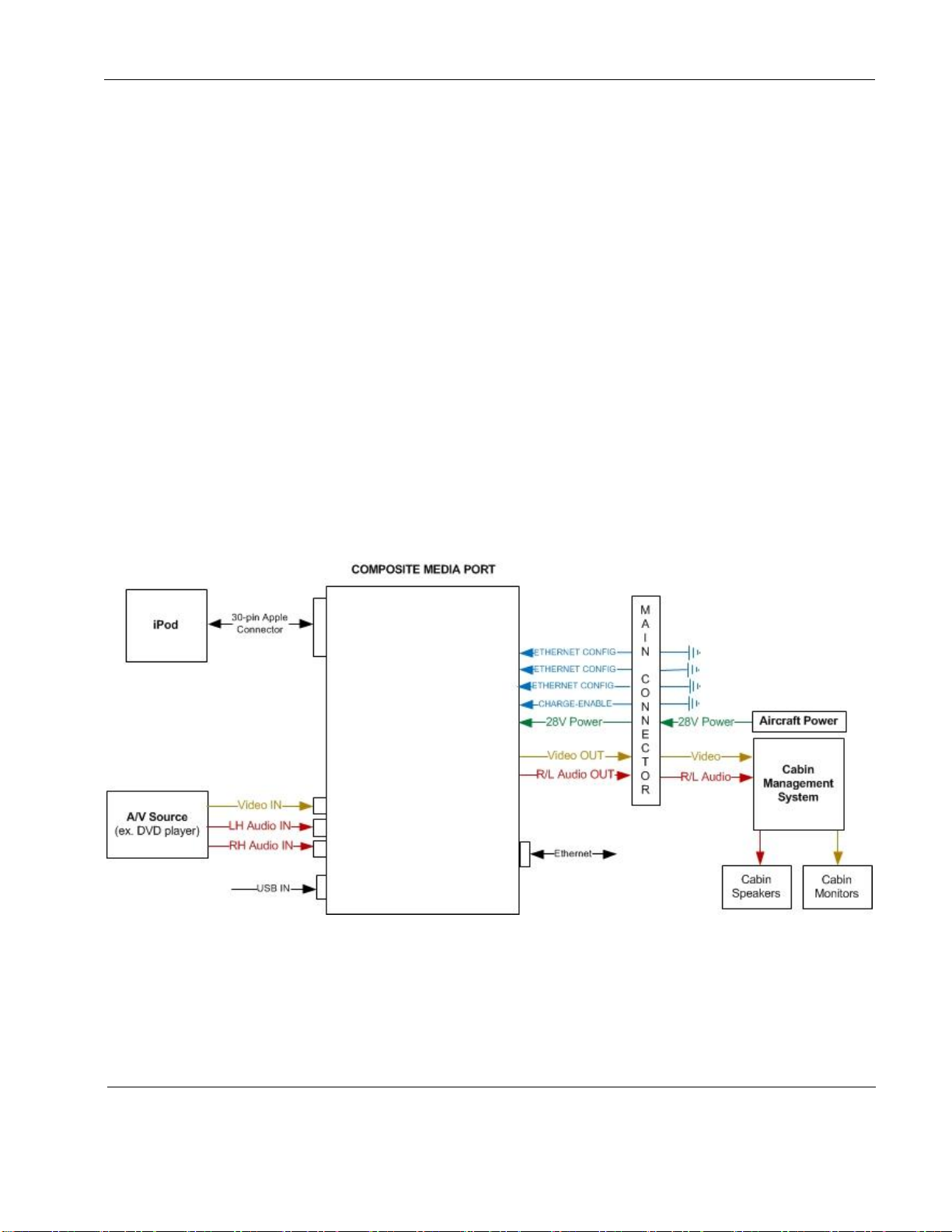
The panels contain a 30-pin iPod®dock connector as well as a separate feed-through style
connection for use with one of three possible audio/video sources:
Composite/RCA –(P/N 0700-203)
VGA –(P/N 0700-204)
HDMI –(P/N 0700-205)
Made for:
iPhone 4®, iPhone 3GS®, iPhone 3G®, and iPhone®
iPod touch®(1st, 2nd, and 3rd generation)
iPod nano®(3rd, 4th, and 5th generation)
iPod classic®
The Media Port panels feature a micro USB port for software loading and an Ethernet port for
optional control of an iPod from a cabin management system (CMS). To allow charging of an iPod
or iPhone, the design converts standard 28V DC aircraft power down to 5V DC power.
The panel’s basic internal circuitry allows passengers the option to control the iPod directly, or to
control a docked iPod/iPhone from the CMS via the Ethernet interface. The dock will translate
control commands received from the CMS into the appropriate commands for the iPod, and will
likewise transmit response data from the iPod back to the CMS.
This manual provides general instructions about how to install all of the Media Port models onto
your aircraft. It contains everything you need to know to wire the panels and confirm that they are
functioning correctly.
For more information about Rosen’s Media Ports, please contact Rosen Sales or Technical
Support.
Note: Only trained and qualified personnel should perform installation and service.
1.1. Additional System Materials
Documentation for the Rosen Media Ports is available on the Rosen website at
www.rosenaviation.com.
Outline & Installation Drawings for each model
Technical Manual
From the Rosen Aviation home page, select the Products tab and browse by product category.
Please contact Technical Support if you cannot find the drawing you need.

Rosen Aviation Media Ports
Document Number: 104375
Revision: B
Date: 06/06/12
Template: 4.2.3-6-FM; Revision A; 16 May, 2005
Page 5 of 15
1.1.1. Connector Kits
The following connector kits (sold separately) are recommended:
Connector kit—13W3 male (P/N 0300-056)
Connector kit—RJ45 plug (P/N 0300-050)
VGA connector kit—HD15 male with backshell (P/N 0300-055)
DVI connector kit—male (P/N 0300-029)
2. SYSTEM INTEGRATION
The Media Port panel acts as an input portal to interface audio/video source equipment with the
cabin’s in-flight entertainment system. The electrical design, board circuitry, software, and iAP are
identical on all three models of the Rosen Media Ports. The panels vary only by the secondary
audio/video feed-through connection (Composite, VGA, or HDMI).The following diagrams show
the different system interconnects.
The Composite Media Port consists of an iPod dock and a separate RCA input connector for a
secondary Composite audio/video source. The panel has only one audio/video output, so it uses a
basic network of source selection relays to feed through either the iPod or the RCA Composite
audio/video data. It will default to output the RCA audio/video data until you connect an iPod, at
which point the output will switch to the iPod data.
Figure 1 System diagram for Composite Media Port

Rosen Aviation Media Ports
Document Number: 104375
Revision: B
Date: 06/06/12
Template: 4.2.3-6-FM; Revision A; 16 May, 2005
Page 6 of 15
The VGA Media Port consists of an iPod dock and a separate feed-through style VGA connector
for RGB video. This panel has one dedicated audio/video output for the iPod and a separate
dedicated output for the RGB video (such as a laptop). The VGA data feeds through
independently of the relays, so that when the iPod is not installed, the relays are open.
Figure 2 System diagram for VGA Media Port
The HDMI Media Port consists of an iPod dock, a composite video output, and a separate feed-
through HDMI connector for high-definition audio/video output. The HDMI audio/video data feeds
through independently of the relays, so that when the iPod is not installed, the relays are open.
Figure 3 System diagram for HDMI Media Port

Rosen Aviation Media Ports
Document Number: 104375
Revision: B
Date: 06/06/12
Template: 4.2.3-6-FM; Revision A; 16 May, 2005
Page 7 of 15
3. INSTALLATION GUIDELINES
Install the Media Ports horizontally (flat), so that the iPod rests in an upright (vertical) orientation
when connected. No special mounting tools are required to install the panels. The following figures
show the general dimensions for the Media Port panels. A cutout in the aircraft panel may be
required and the use of a template or fixture may be necessary.
Outline and Installation drawings are available on Rosen’s website www.rosenaviation.com to
assist in the installation process.
Figure 4 Cutout dimensions
Figure 5 Side view dimensions of a Media Port panel
3.1. Cooling and Ventilation
The Media Port panels are cooled using natural convection and do not require any external
forced-air cooling.
Compress the
two mounting
spring clips to
secure the panel
in the cutout
Removable bezel for
custom plating or
painting

Rosen Aviation Media Ports
Document Number: 104375
Revision: B
Date: 06/06/12
Template: 4.2.3-6-FM; Revision A; 16 May, 2005
Page 8 of 15
4. PINOUTS
There are several ways to connect Media Ports to an aircraft’s entertainment system.
Pay close attention to the pinout descriptions on the Outline and Installation drawings to assist in
completing the wiring connections.
Note: Media Ports is for entertainment purposes only; connect to a non-critical power bus.
4.1. P1 Input / Output Connector
Connector Type: 13W3 female
Mate: 13W3 male
Rosen Connector Kit: 0300-056 (sold separately)
Pin #
Function
1
28V power
2
Audio left
3
Audio right
4
A/V return
5
Charge Config
6
28V return
7
GND
8
ETH Address Config 0
9
ETH Address Config 1
10
ETH Address Config 2
A1
Y
A2
Pb/Composite
A3
Pr
Notes:
Pin 5
The iPod will charge when this pin is set to GROUND, and it will not charge when
set to OPEN.
4.2. Ethernet Address Configuration
You can configure the ethernet address of each Media Port unit for a different static IP address.
The ethernet address is set via configuration strapping pins on the P1 Connector. The table
below lists the available ethernet address configurations
Controls iPod charging

Rosen Aviation Media Ports
Document Number: 104375
Revision: B
Date: 06/06/12
Template: 4.2.3-6-FM; Revision A; 16 May, 2005
Page 9 of 15
Table 1 Ethernet address configurations
Unit
ETH Address
Config 0 (P1-8)
ETH Address
Config 1 (P1-9)
ETH Address
Config 2 (P1-10)
Static IP Address
Address #1
Open
Open
GND
10.0.0.150
Address #2
Open
GND
Open
10.0.0.151
Address #3
Open
GND
GND
10.0.0.152
Address #4
GND
Open
Open
10.0.0.153
Address #5
GND
Open
GND
10.0.0.154
Address #6
GND
GND
Open
10.0.0.155
No Config
Open
Open
Open
NONE
DHCP
GND
GND
GND
Dynamic
Use the optional Ethernet port to control an iPod and Media Port from a cabin management
system. To control these devices from a cabin management system via Ethernet, the cabin
management system must implement the protocol as defined in the Rosen Media Port Interface
Control Document (P/N 104046). To obtain a copy, please contact Rosen Tech Support.
5. INITIAL POWER UP
To connect a Media Port:
1. Make sure to turn off the power before connecting the unit.
2. Ensure a positive ground connection on the Media Port’s housing.
3. Connect 28VDC power and audio/video sources to the input/output connectors.
4. Connect the audio/video source to the rear connector. Confirm that audio/video plays
on a display and through the speakers. For testing purposes, plug a laptop into the
VGA Media Port or a Blu-ray player into the HDMI connector. For Composite, attach
the video and audio to the Media Port’s RCA input jacks, as shown below.
Figure 6 Media Port overview showing RCA input jacks
Jaws
Release mechanism
Apple connector
Video
Audio left
Audio right

Rosen Aviation Media Ports
Document Number: 104375
Revision: B
Date: 06/06/12
Template: 4.2.3-6-FM; Revision A; 16 May, 2005
Page 10 of 15
5. Connect an iPod or other Apple product to the Apple connector and squeeze both
padded jaws snuggly around the device using your thumb and index finger. These
stabilize and protect your device in case of turbulence.
For the composite/RCA model, the panel will default to output audio/video from
equipment connected to the RCA jack until you connect an iPod. Then the output will
switch to the iPod audio/video data. If charging is configured, devices are charged
automatically during streaming.
Note: The volume for recorded movies may be much lower than that of music.
All iPod Touch 1st generation devices require iOS 3 to work
properly with Media Ports.
6. To release the jaws, pull forward on the release mechanism button. The jaws will
expand to allow easy removal of the Apple device.
Do not plug or unplug the Media Port while power is applied.
When cycling power, leave panel off for 20 seconds before
restoring power.
5.1. Maintenance
The Media Ports do not require any periodic maintenance; however, take care not to spill any food
or liquid on the Media Port. In case the panel gets wet:
1. Disconnect removable devices from the panel.
2. Blot away any excessive moisture with a clean, dry paper towel.
3. Remove the bezel with a non-marring, plastic tool.
4. Allow the Media Port to dry thoroughly before replacing the bezel and connecting any
devices to it.
5.1.1. Removing a Bezel
You may need to remove a Media Port bezel for maintenance or for custom
painting/plating. To remove a bezel:
1. Using a non-marring, plastic tool, gently lift up under both rear corners, as shown
below. The bezel will pop off.
Figure 7 Bezel for a VGA Media Port
Lift up under both
rear corners of the
bezel

Rosen Aviation Media Ports
Document Number: 104375
Revision: B
Date: 06/06/12
Template: 4.2.3-6-FM; Revision A; 16 May, 2005
Page 11 of 15
2. To replace the bezel, bring the bezel and housing assemblies together, align the two
mounting tabs with the recesses in the bezel (shown below) and the lip in the front
slot, and press down on the two rear corners of the bezel to secure.
Figure 8 Proper alignment of housing and bezel mounting tabs
6. TECHNICAL REFERENCES AND SUPPORT
Always check the Rosen Aviation website under the Products tab
to ensure that you are working with the most current revision of
technical documentation.
Table 2 Technical references
Product
Part Number
Location
Media Port Interface Control Document
104046
Rosen Technical Support
Outline & Installation Drawings
0700-20x
www.rosenaviation.com
Apple iOS 3 (operating system)
N/A
www.apple.com
6.1. Troubleshooting
If the Media Port does not function properly, refer to the following troubleshooting table for
symptoms and possible solutions before contacting Rosen technical support.
Note: Always use an oscilloscope to verify the video signal. Always use a multimeter to verify
voltages. Check actual results against the requirements described in this manual.
Two mounting
tabs aligned with
bezel recesses

Rosen Aviation Media Ports
Document Number: 104375
Revision: B
Date: 06/06/12
Template: 4.2.3-6-FM; Revision A; 16 May, 2005
Page 12 of 15
Table 3 Troubleshooting tips for Media Ports
Problem
Possible Solutions
Connected Apple device not
charging
Ensure that the charging discrete input is set to GROUND. See Section
4.1, P1 Input / Output Connector on page 8.
Cannot control connected
Apple device remotely
Ensure the IP configuration discretes are set to match the desired IP
address.
Unable to control an iPod
touch (1st generation)
An iPod touch (1st generation) must have iOS 3 installed to work
properly with Media Ports. Download the iOS 3 from www.apple.com/.
No video from audio/video
source connected to RCA
jacks
Audio/video from the connected Apple device has priority over the
audio/video from the RCA jacks. To receive audio/video from the RCA
jacks, remove the Apple device from the Media Port.
Unable to control the
connected Apple device
using the Apple device user
interface
To control audio/video using the Apple device user interface directly (no
remote control from a cabin management system), the IP configuration
discretes must all be set to OPEN (Ethernet OFF).
6.2. RTCA DO-160F Qualifications for Displays
The table below shows the DO160 compliance of the Media Ports, unless otherwise noted.
Omitted categories are not applicable to the product or its expected installation.
Table 4 DO 160 Level F test criteria
Description
Section
Category
Comments
Temperature and Altitude
4
Ground Survival/Short-Time Operating
Low Temp
4.5.1
A1
Operating Low Temperature
4.5.2
A1
Ground Survival/Short-Time Operating
High Temp
4.5.3
A1
Operating High Temperature
4.5.4
A1
In-flight Loss of Cooling
4.5.5
N/A
Not applicable
Altitude
4.6.1
A1
Decompression
4.6.2
N/R
Not required
Overpressure
4.6.3
N/R
Not required
Temperature Variation
5
Temperature Variation
5.3.1
C
Humidity
6
Humidity
6.3.1
A
Operational Shocks & Crash Safety
7
Operational Shocks
7.2.1
B
Crash Safety (Impulse)
7.3.2
B
Crash Safety (Sustained)
7.3.3
B

Rosen Aviation Media Ports
Document Number: 104375
Revision: B
Date: 06/06/12
Template: 4.2.3-6-FM; Revision A; 16 May, 2005
Page 13 of 15
Description
Section
Category
Comments
Vibration
8
Random Vibration –Fixed Wing Aircraft
8.5.2
S (Curve B)
Explosion Proofness
9
Explosion Proofness
9.0
N/A
Not applicable
Waterproofness
10
Waterproofness
10.3.2
W
Fluids Susceptibility
11
Fluids Susceptibility
11.0
N/A
Not applicable
Sand and Dust
12
Sand and Dust
12.0
N/A
Not applicable
Fungus Resistance
13
Fungus Resistance
13.0
N/A
Not applicable
Salt Fog
14
Salt Fog
14.0
N/A
Not applicable
Magnetic Effect
15
Magnetic Effect
15.3
A
Power Input
16
Normal Operating Conditions (DC)
16.6.1
Average Value Voltage (DC)
16.6.1.1
B
Ripple Voltage (DC)
16.6.1.2
B
Test Covered in Section 18
Momentary Power Interruptions (DC)
16.6.1.3
B
Normal Surge Voltage (DC)
16.6.1.4
B
Engine Starting Under Voltage Operation
(DC)
16.6.1.5
B
Abnormal Operating Conditions
16.6.2
Voltage Steady State (DC)
16.6.2.1
B
Low Voltage Condition (DC)
16.6.2.2
B
Momentary Under Voltage (DC)
16.6.2.3
B
Abnormal Surge Voltage (DC)
16.6.2.4
B
Voltage Spike
17
Voltage Spike
17.4
B
Audio Frequency Conducted
Susceptibility
18
AF Conducted Susceptibility- Power
Inputs
18.3.1
B
Induced Signal Susceptibility
19
Induced Signal Susceptibility
19.0
N/R
Not required

Rosen Aviation Media Ports
Document Number: 104375
Revision: B
Date: 06/06/12
Template: 4.2.3-6-FM; Revision A; 16 May, 2005
Page 14 of 15
Description
Section
Category
Comments
Radio Frequency Susceptibility
20
Conducted Susceptibility (CS) –
10kHz to 400MHz
20.4
T
Radiated Susceptibility (RS) –
100MHz to 18GHz
20.5
T
Emission of Radio Frequency Energy
21
Conducted RF Emission
21.4
M
Radiated RF Emission
21.5
M
Electrostatic Discharge (ESD)
25
Electrostatic Discharge (ESD)
25.5
A
Flammability
26
N/A
Flammability testing in
accordance with 14 CFR
25.853 Appendix F
6.3. Specifications
Table 5 Media Ports panel performance specifications
Nominal Voltage/Current Draw
28VDC/50mA
Inrush Current
2A @ 200µsec
Op Voltage Range
18-32VDC
Maximum Current Draw
0.50 A
Power Consumption
14 W Max
Weight
Composite - .81 lbs. [ 0.37 kgs.] 10%
VGA - .85 lbs. [ 0.39kgs.] 10%
HDMI - .93 lbs. [0.42 kgs.] 10%
Table 6 Media Ports panel environmental specifications
Operating Temperature
-15ºC –55ºC
Altitude
15,000ft
Humidity
95%RH
Vibration
1.48 grms
Power Input
DO-160F Cat B
Radio Frequency Susceptibility
DO-160F Cat T
Emission of RF Energy
DO-160F Cat M
Waterproofness
DO-160F Cat W

Rosen Aviation Media Ports
Document Number: 104375
Revision: B
Date: 06/06/12
Template: 4.2.3-6-FM; Revision A; 16 May, 2005
Page 15 of 15
7. DEFINITIONS
CFR
Code of Federal Regulations
CMS
Cabin Management System
DCV
Direct Current Volts –voltage from an aircraft battery or generator
DHCP
Dynamic Host Configuration Protocol
DVI
Digital Visual Interface
HD
High Definition
HDMI
High Definition Multimedia Interface
iAP
Apple protocol for iPod, iPod touch, etc.
P/N
Part Number
RCA
(Radio Corporation of America) composite video & analog audio connection
RGB
Red, Green, Blue
R/L
Right/Left
VGA
(Video Graphics Array) RGB video connection
W
Watts
8. REVISION HISTORY
Revision E is limited to draft or prototype documents. Revisions I,
O, Q, S, X and Z are not to be used.
Revision
Date
Revision Description
EC
A
08/31/11
Initial release
11544
B
06/06/12
Update pinout and IP address configurations
12-0315
Table of contents