manuals.online logo
Brands
  1. Home
  2. •
  3. Brands
  4. •
  5. Kenwood
  6. •
  7. Turntable
  8. •
  9. Kenwood KD-47F User manual

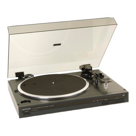
Kenwood KD-47F User manual

-FULL
AUTOMATIC,
TURNTABLE
KD-47F
KD-47FC(FCL
INSTRUCTION
MANUAL
Introduction
Your
choice
of
this
product
indicates
that
you
are
a
devotee
to
excellence
in
sound
reproduction.
We
appreciate
your
patronage
and
take
pride
in
the
long
tradition
of
quality
components,
that
our
company
represents.
So
that
you
can
get
the
most
out
of
your
unit,
we
suggest
that
you
take
the
time
to
read
through
this
manual
before
you
hook
up
and
operate
your
system.
This
will
acquaint
you
with
operating
features,
and
system-connection
considerations,
so
that
your
listen-
ing
pleasure
will
be
enhanced
right
from
the
start.
You
will
notice
that
in
all
aspects
of
planning,
engineering,
styling,
operating
convenience
and
adaptability,
we
have
sought
to
anticipate
your
needs
and
desires.
Keep
this
manual
handy
for
future
reference.
For
your
records
.
4
Record
the
serial
number,
found
on
the
back
of
the
unit,
in
the
spaces
designated
on
the
warranty.
card,
and
in
the
space
provided
below.
Refer
to
the
model
and
serial
numbers-whenever
you
call
upon
your
dealer
for
information
or
service
on
this
product.
Model
_______.,
Serial
Number
Unpacking
,
ne
Unpack
the
unit
carefully
and
make.
sure
that
all
ac-
cessories
are
put‘aside:
so
they
will
‘not
be
lost.
Examine
the
unit
for*
any
.possibility
of
shipping
damage.
If
your:unit:issdamaged.
or
fails
to
operate,
notify
your
dealer
immediately.
If
your
unit
was
shipped
to*you
diréctlynotify:the
shipping
company
without
delay.
Only
the
consignee
(the
person
or
company
receiving
the
unit)
can
file
a
claim
against
the
carrier
for
_
shipping
damage.
We:recommend:
that
you
retain
the
original
carton
and
packing
:materials
for
use
should
you
transport
or
ship
the
unit
in
the
future.
.
Contents
A
Before
applying
POWET
........-....eeeeeurrreeettteterees
2
A
Safety
precautions
............::ssceeceeserreee
reeset
tieees
2
“A
Important
safeguards
.........c:ceeeeeeeeeeerereeeestereee
3-4
Parts
NOMENCIatUre
........
2...
cece
eee
eee
ec
een
ee
newts
eneees
5
-Reassembly:and.connection.......6.....:sesceveeeeeeeeeees
6
An
example.
of
system
control
connection
Caution:
Read
the
following
pages
marked
in
A
carefully
to
keep
your
safety.
(Except
EUOpe)
.........ceeceeeee
eee
eeeee
ees
dusdeaateasiees
7
:
KENWOOD
©PRINTED
IN
JAPAN
1B50-8840-08(K,P,U,UE,M,X|EXT)
882
11098765432:
a)
Difference
by
models
|
-
Others
KD-47F
Cartridge
Supplied
Supplied__|
Supplied.
KD-47FC
Sumplied:
|
Dust
cover
|
Supplied
KD-47FCL
Supplied
Supplied
_
Accessories
@
EP
adaptor:
2.
cocsecc
ett
ed
eee
ee
esrteneeie
a
bseeetel
es
1
e
Dust
cover
hinge
(Except
some
areaS).........-.....06
2
6.
Turntable
belt
ccc
.ccscicsadavetang
en
eedacenaceeedeea
tuna
an
1
e
Turntable
sheet..................
Rehan
tantwees
Sponitet
1
e
System
control
cord
(Except-some.areas)..........0-+-
1
Operating
instructions.
............:.ccceeeeetaeenrett
trees
8
Maintenance...............
eh
eas
lat
Ris
Padceiett
sO
In
case
of
difficulty
............
ccc
cece cese
eee
ee ee
eens
eeeeee
ee
10
Specifications
.............ccceceeseeeeeeeeeeeeeeaeeeetaeeeentes
11
|
Before
applying
power.
A\
Caution:
Read
this
page
carefully
to
keep
your
safety.
Important!
U.S.A.,
Canada,
Australia
and
Europe
Units
shipped
to
the
U.S.A.
and
Canada
are
designed
for
operation
on
120
V
AC
only.
Units
shipped
to
Australia
are
designed
for
operation
on
240
V
AC
only.
Units
shipped
to
Europe
are
designed
for
operation
on
220
V
AC
only.
These
units
are
not
equipped
with
an
AC
voltage
selec-
tor
switch
and
the
discussion
of
such
a
switch
that
follows,
should
be
disregarded.
|
All
other
countries
Units
shipped
to
countries
other
than
the
above.
coun-
tries
are
equipped
with
an
AC
voltage
selector
switch.
Refer
to
the
following
paragraph
for
the
proper.
setting
of
this
switch.
AC
voltage
selection
This
unit
operates’on
110°-
120
volts
or
220
-.240
volts
AC.
The
AC
voltage
selector
switch
near
the
center
spindle
(under
the
turntable
platter)
is
set
to
the
voltage
that
prevails
in
the
area
to
which
the
unit
is
shipped.
Before
connecting
the
power
cord
to
your
AC
outlet,
make
sure
that
the
setting
position
of
this
switch
matches
your
line
voltage.
If
not,
it
must
be
set
to
your
'
voltage
in
accordance
with
the
following
direction.
Note:
vollage
duo
to
improper
seting
ofthe
AC
wotage
selector
switch.
Safety
precautions
WARNING:
TO
PREVENT
FIRE
OR
ELECTRIC
220
v
SHOCK,
DO
NOT
EXPOSE
THIS
AP-
240
V
PLIANCE
TO
RAIN
OR
MOISTURE.
lever
is
locked
in
lever
is
locked
in
AC
110-120V~
AC
220-240V~
position.
position.
:
1.
Remove
the
plate
pad
and
screw
with
screw
driver.
This
shows
switch
This
shows
switch
2.
Move
switch
lever
to
match
your
line
voltage.
CAUTION
3.
Attach
the
plate
pad
and
screw
as
shown
figures.
:
RISK
OF
ELECTRIC
SHOCK
DO
NOT
OPEN
AC
voltage
selector
switch
,
This
riaaie
is
indicated
on
the
bottom
plate
of
the
ves
.
unit.
CAUTION
‘CAUTION:
TO
REDUCE
THE
RISK
OF
ELECTRIC
SHOCK,
DO
NOT
SE
CREEEET
HG
Cock
‘REMOVE
COVER
(OR
BACK).
NO
USER-SERVICEABLE
PARTS
INSIDE.
DO
NOT
OPEN
y
-
|
REFER
SERVICING
TO
QUALIFIED
SERVICE
PERSONNEL.
THE
LIGHTNING
FLASH
WITH.
ARROWHEAD
SYMBOL,
WITHIN
AN
EQUILATERAL:
TRIANGLE,
|S
INTENDED
TO
ALERT
THE
USER
TO
THE
PRESENCE
OF
UNINSULATED
‘‘DANGEROUS
©
VOLTAGE”
WITHIN
THE
PRODUCT’S
ENCLOSURE
THAT
MAY
BE
OF
SUFFICIENT.
MAGNITUDE
TO
CONSTITUTE
A
‘RISK
-OF
ELECTRIC
SHOCK
TO
PERSONS.
THE
EXCLAMATION
POINT
WITHIN
AN
EQUILATERAL
TRIANGLE
1S
INTENDED
TO
ALERT
THE
USER
TO
THE
PRESENCE
OF
IMPORTANT
OPERATING
AND
MAINTENANCE
(SERVICING)
IN-
STRUCTIONS
IN
THE
LITERATURE
ACCOMPANYING
THE
APPLIANCE.
2
KD-47FIKD-47FC(FCL)
(K)
Important
safeguards
Please
read
all.of
the
safety
and
operating
instructions
before
operating
this
unit.
For
best
results,
follow
all
warnings.
placed.
on.
the
unit
and
adhere
to
the
operating
and
use
instructions.
These
safety.
and
operating
INSTMEUONS
should
be
retained
for
future
reference.
1.
Power
sources
—
The
unit
should
be
connected.
to
a
power
supply
only
of
the
type
described
in
the
operating
instructions
or
as
marked
.on
the
ap-
pliance.
2.
Power-cord
.
protection
—
Power-supply
cords
should
be
routed
so
that
they
are
not
likely
to
be
walked
on
or
pinched
by
items
placed
upon
or
against
them,
pay
particular
attention
to
cords
at
plugs,
convenience
receptacles,
and
the
point
where
they
exit
from
the
unit.
Never
pull
or
stretch
the
cord.
3.
Grounding
or
polarization
—
Precautions
that
~
should
be
taken
so
that
the
grounding
or
polariza-
tion
means
of
this
unit
is
not
defeated.
4.
Ventilation
—
The
unit
should
be
situated
so
that
its
location
or
position
does
not
interfere
with
its
proper
ventilation.
To
maintain
good
ventilation,
do
not
put
records
or
a
table-cloth
on
the
unit.
Place
the
unit
at
least,
10
cm:away
from
the
walls.
Do
not
use
the
unit
on
a
bed,
sofa,
rug
or
similar
surface
that
may
block
the
ventilation.
openings.
5.
Water
and
moisture
—
The
unit
should
not
be
_used
near
water.—
for
example,
near
a
bathtub,
©
washbowl,
kitchen
sink,
laundry
tub,
in
a
wet
base-
‘ment;
‘or
near
a
swimming
pool,
etc.
6.
9.
10.
A\caution
.?
Read
this
page
carefully
to
keep
your
safety.
Temperature
—
The
unit
may
not
function:
pro-
perly
if
used
at
extremely
low,
or
freezing
temperatures.
The
ideal
ambient
temperature
is
above
+5°C
(41°F).
.Heat
—
The
unit
should
be.
situated
away
from
heat
sources
such.
as
radiators,
heat
registers,
stoves,
or
other
units
{including
amplifiers)
that
produce
heat::
:
.
Electric
shock
—
Care
‘should
be‘taken
so
that
object
do
not
fall
and
liquid
are
not
spilled
into
the
enclosure
through
openings.
If
a
metal
object,
such
‘as
a
hair
pin
or
a
needle,
comes
into
contact
with
the
inside
of
this
unit,
a
dangerous
electric
shock
-
may
result.
For
families
with
children,
never
permit
children
to
put
enn
ae
especially
metal,
inside
this
unit.
Enclosure.
removal
—
Never
remove.
the
enclosure.
If
the
internal
parts.are
touched
ac-
cidentally,
a
serious
electric
shock
might-occur.
‘AC
outlets’:
—
Do
not
connect
other
audio
equip-
ment
with
a
power
consumption
larger.
than
that
specified
to
the
AC
outlet
on
the
rear
panel.
Never
connect
:other..electrical
units,
such
.as.an
iron
or
todster,
to
it
to
prevent
fire
or
electric
shock:
KD-47F/KD-47FCIFCL)
(Kk)
3
A\Caution:
-Read
this
page
carefully
to.
keep
your
safety.
11.
Magnetic
fields
—
Keep
the
units:
away
from’a
source
of
magnetic
fields
such
as
TV
sets,
speaker
systems,
radios,
motorized
toys
or
magnetized
ob-
jects.
.
12.
Cleaning
—
Do
not
use
volatile
solvents
such
as
alcohol,
paint
thinner,
gasoline,
or
benzine,
etc.
to
clean
the
cabinet.
Use
a
clean
dry
cloth.
13.Nonuse
periods
—
The
power
cord
of.
the
unit
should
be
unplugged
from
the
outlet
when
left
’
unused
for
along
period
of
time.
14.
Abnormal
smell
—
If
an
abnormal
smell
or
smoke
is
detected,
immediately.
turn
the
power
OFF
and
pull
out
the
power
cord.
Contact
your
dealer
or
nearest
service
station.
rice
POWER
OFF!
it
&
3
15.
Damage
requiring
service.
—
The
unit
should
be
serviced
by
qualified
service
‘personnel
when:
A.
The
power-supply
cord
or
the
plug
has
been
damaged;
or
‘B.
Objects
have
fallen,
or
liquid
has
been
‘spilled
into
the
unit;
or
,
C.
The
unit
has
been
exposed
to
rain;
or
D.
The
unit
does
not
appear
to
operate
normally
or
éxhibits
a
marked
change
in
performance;
or
E.
The
unit
has
been
dropped,
or
the
enclosure
damaged.
ba
16.
Servicing
—
The
user
should
not
attempt
to
ser-
vice
the
unit
beyond
that
described:in'the
operating
instructions.
All
other
servicing
should
be
referred
to
qualified
service
personnel.
17.
Outdoor
antenna
grounding
—
|f
an_
outside
antenna
is
connected
to.
the
receiver,
be
sure
the
antenna
system
is
grounded
so
as
to
provide
some
protection
against
voltage
surges
and
built
up
static
charges.
Section
810
of
the
National
Elec-
trical
Code,
ANSI/,
NFPA
No.
70—1984,
provides
information
with
respect
to
proper
grounding
of
the
mast
and
supporting
structure,
grounding
of
the
lead-in.
wire
to
an
antenna
discharge:
unit,
size
of
grounding
conductors,
location
of
antenna-
discharge
unit,
connection.
to.
grounding
elec-
trodes,
and
requirements
for
the
grounding
‘elec-
trode.
See
Figure.
,
®Usea
No.
10
AWG
(5.3
mm?)
copper,
No.
8
AWG
(8.4
mm?)
alu-
minum,
No.
17
AWG
(1.0
mm?)
copper-clad
steel
or
bronze
wire,
or
larger,
as
a
ground
wire.
>Secure
antenna
lead-in
and
ground
wires
to
house
with
stand-off
in-
sulators
spaced
from
4
—
6
feet
(1.22.—
1.83
m)
apart.
:
©
Mount
antenna
discharge
unit
as
close
as
possible
to
where
lead-in
enters
house.
4Use
jumper
wire
not
smaller
than
No.
6
AWG
(13.3
mm?)
copper,
or
the
equivalent,
when
a.
separate
antenna-grounding
electrode
is
used.
See
NEC
Section:810-21(j).
18.
Power
lines
—
An
outdoor
antenna
should
be
located
away
from
power
lines.
Notes:
POWER
LINES
SERVICE
ENTRANCE
CONDUCTORS
“STANDOFF
INSULATORS?
MAST
SERVICE
ENTRANCE
EQUIPMENT
ANTENNA
=LEAD-IN
WIRE
ANTENNA
DISCHARGE
UNIT®
POWER
SERVICE
GROUNDING
ELECTRODE
SYSTEM
{e.g.
interior
metal
water
pipe}
BONDING
JUMPER*®
GROUND
CLAMPS
OPTIONAL
ANTENNA
GROUNDING
ELECTRODE
DRIVEN
8
FEET
(2.44
m)
INTO
THE
EARTH
IF
REQUIRED
BY
LOCAL
CODES.
SEE
NEC
SECTION
810-21(f).
.
FIGURE
EXAMPLE
OF
ANTENNA
GROUNDING
ACCORDING
TO
THE
NATIONAL
ELECTRICAL
CODE
INSTRUCTIONS
CONTAINED
IN
ARTICLE
810
—
‘'RADIO.
AND
TELEVISION
EQUIPMENT’’
i.
1.
ltem
3
is
not
required
except
for
grounded
or
polarized
equipment.
2.
Item
10
is
not
required
except
for
units
provided
with
AC
outlets.
.
3.
Item.17
and
18
are
not
required
except
for
units
provided
with
antenna
terminals.
4
KD-47F/KD-47FC(FCL)
(K)
Parts
nomenclature
‘-@
Check
that
the
packing
carton
contains
all
the
com-
=
*_-See
page
6
for
assembly
procedures.
ponent
parts
shown
in
the
figure
below
before
you
begin
to.
assemble
the
turntable.
,
¢.
Keep
the
packing
materials
in
case
you
have
to
“repack
in
future
(for
moving,
servicing,
etc.).
Dust
cover
:
Hinge
No.
dust.,
cover.
and/or.
car-
|.
tridge
is
provided
with
this
unit.
shipped
to
some
areas.
For
details,
please
refer
to
the
cover
page.
Turntable
sheet
o-——
EP
adaptor
Turntable
platter
\
Af}
|
ble
belt
~
AK
oS
J)
Turntable
bi
:
;
;
Ribbon
tape
RCA
pin
plug
cords
: ;
Arm
elevator
:
{ffi}
aN
: :
a".
.
7
Ground
lead
>:
:
AC
cord
EP
adaptor
stay
Center
spindle
Tonearm
Arm
rest
Cartridge
Size
selector
Power
KENWOOD
fu
automa
POWER
switch
CUEING
switch
SPEED
selector
PLAY/CUT
key
SPEED
indicator
st
KD-47FIKD-47FC(FCL)
(k)
5
Reassembly
and
connection
Units
shipped
to
some
areas
are
sold
without
phono
cartridge.
Before
proceeding
with
assembly,
install
the
cartridge
in
the
head-shell
on
page
9.
When
your
unit
is
equipped
with
a
V-68
cartridge,
proceed
as
follows.
Be
sure
to
follow
steps
1~4
in
the
sequence
given.
1.
Engage
the
drive
belt
with
the
motor
pulley.
Set
the
platter
carefully
on
the
spindle.
Using
the
ribbon
tape,
engage
the
drive
belt
with
the
motor
pulley,
as
shown
below.
Remove
the
ribbon
tape
and
place
the
rubber
mat
on
the
platter.
-
Motor
pulley
2.
Connections
Turn
off
the
power
to
your
amplifier
or
receiver.
Con-
nect
the
RCA
pin-plug
cords,
ground
lead,
then
the
AC
cord.
,
Except
Europe
KD-47F/KD-47FC(FCL)
{t_t
|
|
[|
=
System
control
terminal
i
nie
I
al
a]
Ground
lead
RCA
pin-plug
cords
:
Control!
amplifier
u
AAT
oe
Olafeoeoeciee-|
je.
“IX
000001004
(04
Wf
to}
re
XA
iy
,
a
a
Ee
.
White
PHONO
jacks
Red
1}
Power
amplifier
Note:—___—______
—_———_—_———-
As.a
microcomputer
is
used
inthis
unit,
beat
noise
may
be
generated
when
receiving
broadcasting
with
the
tuner.
In
such
cases,
turn.
off
.
the
power
switch
of
this
unit
or
adjust
the
tuner
antenna.
Incorrect
ground
lead
connection
may
sometimes
make
impossible
to
activate
the
muting
feature
and
system
contro!
operation.
6
KD-47F/KD-47FCIFCL)
(K)
Europe
KD-47F
=F
ae
has
Se
(J
RCA
pin-plug
cords
To
AC
outlet
Ground
lead
-
o
:
rea
in
Sdlods~
D
O0|OOOOs
Stereo
amplifier
(or
receiver)
—
To
AC
outlet
PHONO
jacks
3.Connecting
the
system
control
terminal
(Ex-
cept
Europe)
The
system
control
terminal
is
the
control
comune
for
synchro
recording
when
KD-47F/KD-47FC(FCL)
is
connected
to
a
unit.
which
is
equipped
with
a
system
control
terminal.
Connect
this
terminal
to
the
system
°
control
terminal
of
the
related
unit
with
the
supplied
system
control
cord.
For
synchro
recording,
the
RCA
pin-plug
cords
and
ground
lead
should
be
connected.
(Synchro
recording
is
not
possible
when
only
the
system
control
cord
is
connected.)
Set
the
cassette
deck
to
the
recording
mode,
and
press
the
play/cut
switch
(PLAY/CUT),
synchro
recording
will
be
perform-
ed.
For
details,
refer
to
the
Instruction
Manual
of
the
related
unit.
Setting
the
amplifier
This
unit
is
equipped
with-the:MM
cartridge,
TAP
standard.
(Except
some
areas)
Connect
the
RCA
pin-plug
cords
of
this
unit
to
the
PHONO
MM
jacks
of
the
amplifier
or,
set
the
car-
tridge
load
selector
of
the
amplifier
to
MM.
4.
Pull
out
the
stylus
cover
in
the
direction
of
the
arrow.
.
.
Stylus
‘cover
ae
An
example
of
system
control
connection
(Except
Europe)
Turntable
(KD-47F/KD-47FC
(FCL))
Power
amplifier
Control
amplifier
O|@
eeeeeeoe=
|e
eeeeoelees
be
|
©
a®
Xo)
Tuner
=G@E
To
wall
AC
outlet
CD
player
(6c
re
@©e#
©
System
control
cord
The
remote
control
socket
on.
This
unit
is
only
for
use
with
associated
models
which
are
not
available
on
the
U.K.
market.
Note:
For
synchro
recording,
the
RCA
pin-plug
cords
and
.
ground
lead
should
be
connected.
(Synchro
recor-
ding
is
not
possible
when
only
the
system
control
cord
is
connected.)
KD-47FIKD-A7FC(FCL)
(K)
7
Operating
instructions
—
Turn
the
power
on
and
set
a
record
on
the
turn-
table.
Notes
ee
When
the
POWER
switch
is
turned
ON,
the
SPEED
in-
dicator
blinks
automatically.
Select
the
speed
with
the
SPEED
selector
in
this
period.
This
unit
does
not
function
in
so
far
as
the
indicator
blinking.
When
the
cue
is
up
(with
the
CUEING
switch
pressed
in.m
),
the
SPEED
indicator
also
blinks
and
automatic
play
is
not
possible.
To
enable
automatic
play,
bring
the
cue
down
(by
pressing
the
CUEING
switch
out
[1).
Automatic
play
1.
Select
33
1/3
or
45
by
pressing
SPEED
key.
2.
Select
the
record
size
for
30
cm
or
17
cm.
3.
Press
PLAY/CUT
key.
~
Playing
will
start
from
the
first
selection
and
continue
to
the
last,
then
the
tone
arm
returns
to
the
arm
rest
and
the
turntable
stops.
4.
Control
the:
volume
by
VOLUME
control
on
the
amplifier.
e
While
playing,
pressing
PLAY/CUT
or
any
INPUT
key,
except
PHONO
on
the
amplifier,
stops
the
play
(when
system
control
connection),
the
tone
arm
returns
to
the
arm
rest
and
the
turntable
stops.
Note:
Manual
operation
is
necessary
for
25
cm
records
or
other
odd
sizes.
Manual
play
1.
Use
operations
1
and
2
for
automatic
play.
2.
Release
the
tonearm
from
the
armrest
—<=andcon-
|
firm
that.
the
CUEING
switch
is
set
to
(=).
Swing
the
tonearm
over
the
starting
position.
3.
Press
CUEING
switch
(£1).
This
puts
the
tone
arm
on
the
record
and
playing
starts.
At
the
end
of
the
record,
the
tone
arm
returns
to
the
arm
rest
and
the
turntable
stops.
4.
Control
the
volume
by
VOLUME
control
on
the
'
amplifier.
To
stop
the
play
temporarily
Press
CUEING
switch
to
momentarily
stop
playing:
The
tone
arm
leaves
the
record.
To
restart
playing,
press
CUEING
switch
again.
The
record
play
resumes
almost
the
same
position.
System
control
operation
(Except
some
areas)
With
the
KD-47F/KD-47FC(FCL)
connected
to
a_unit.
equipped
with
a
system
control
terminal,
synchro
recording,
automatic
play
operation
and
remote
control
operation
are
possible.
For
detailed
operation
of
system
control,
refer
to
the
instruction
manual
of
the
related
unit.
8
kD-47F/KD-47FC(FCL)
(K)
Maintenance
For
U.S.A.
only
Obtain
the
optionally
available
(TaD)
MM
car-
tridge.
[
With
this
unit;
a
MC
type
cartridge
cannot
be
used.
|
.
Motor
lubrication
The
motor
employs
permanently-lubricated
bearings.
It
will
operate
for
more
than
20,000
hours
without
atten-
tion
to
lubrication.
Periodic
check-up
Because
a
turntable
is
a
mechanical
device
it
is
subject
to
the
effects
of
wear
and
misadjustment
that
occurs
due
to
normal
handling.
Even
if
your
unit
appears
to
function
normally,
a
periodic
check-up
at
intervals
of
two
years
or
so.is
recommended
to
ensure
a
long
ser-
vice
life
and
proper
operation.
Check
with
your
dealer
or
authorized
service
represen-
tative.
Stylus
replacement
A
replacement
stylus
can
be
obtained
from
your
local
dealer.
Always
obtain
the
specified
stylus
N-68.
When
replacing
the
stylus,
take
care
not
to
damage
the
stylus
tip.
The
figure
below
shows
how
to
replace
the
stylus.
Note:
Be
sure
to
turn
off
the
power
of
the
amplifier
when
replacing
the
stylus.
Stylus
cover
Locking
screw
“BE
ar
Pull
out
the
stylus
cover
in
the
direction
of
the
arrow.
Puli
out
the
stylus
in
the
'
direction
of
the
arrow.
How
to
replace
the
cartridge
1.
Remove
the
cartridge
locking
screw.
(To
protect
the
stylus,
remove
the
stylus
assembly
beforehand.)
2.
Pull
out
the
cartridge
from
the
tonearm.
To
install
the
cartridge,
align
the
pins
of
the
cartridge
with
the
connector
of
the
tonearm
and
securely
in-
sert:
KD-47F/KD-47FC(FCL)
(kK)
9
In
case
of
difficulty
If
difficulty
is
experienced
aftér
making
the
initial.set
up,
the
table
below
might
help
to
eliminate
the.
problem.
If
the
trouble
cannot
be
corrected,
check
with
your
dealer.
‘Correction
No
sound
from
both
left
and
right
chan-
nels
or
one
channel.
che
Loud
hum,
no
music.
Loud
hum
with
music.
1.
Turntable
output
cables
discon-
nected.
2.
The
function
switch
of
the
amplifier
is
not
set
to
PHONO.
Poor
connection
of
turntable
output
cables.
1.
Check
connections
to
amplifier.
2.
Set
the
function
switch
to
PHONO.
Make
solid
connections
to
amplifier.
.
.
Turntable
output
cable
picking
up
hum
from
AC
cord.
.
The
ground
lead
of
the
turntable
is’
not
connected
to
GND
terminal
of
the:
amplifier.
1.
Separate
output
cables
from
AC
cord
or
reverse
AC
cord
plug.
“2.
Connect
the
ground
lead
to
the
GND
terminal
of
the
amplifier.
Buzzing
noise
with
music.
Turntable
output
cable
picking
up
TV
signal.
Relocate
output
cord
for
minimum
pickup.
Howling
drowns
out
music
when
volume
is
increased.
Speaker
vibration
is
picked
up
by
turn-
table.
Separate
turntable
from.
speakers.
Turntable
platter
does
not
turn.
Synchro
recording
is
not
possible.
10
kb-47F/KD-47FCIFCL)
(K)
Poor
AC
plug
contact.
Check
connection.
Make
sure.
AC
outlet
is
active.
Excessive
dust
on
record
or
stylus.
Remove
dust
from
stylus
or
record.
.
The
system
control
cord
is
not
con-
nected.
.
The
cassette
is
not
loaded
correctly.
.
The
record
lock-out
tab
on
the
cassette
has
been
removed.
_
The
cassette
deck
is
in
playback
mode.
1.
Connect
the
system
control
cord
securely.
2.
Load
the
cassette
tape
correctly.
3.
Use
a
new
cassette
or
place
a
piece
of
adhesive
tape
over
the
opening
-
from
which
the
tab
has
been
remov-
ed.
;
4.
Set
the
cassette
deck
in
stop
mode.
Specifications
Motor
and
Turntable
Drive
System..........2e.esseees
Belt-drive
system
Motor
.......c.sececcesecceeenseeee
FG
Servo
Motor
Turntable
Platter
...............
29.6
cm
(11-5/8”)
diameter
0.35
kg
(0.77
Ib)
weight
Speeds..........sceceeecreeeeeaees
2
speeds,
33-1/3
and
45
rpm
Wow
&
Flutter
.............:206
0.05%
(WRMS)
DIN:
0.07%
S/N
(Rumble)
.............2..006
DIN:.
40
dB
(Unweighted)
DIN:
70
dB
(Weighted)
Tonearm
[email protected]
Static-Balanced
Straight
Effective
Tonearm
Length...
Overhang..........ceceseesesseees
Tracking
Error
..........-:2-2+0+
Tracking
Force
Tonearm
222
mm
(8-3/4")
17
mm
(11/16”)
Less
than
2.2°
Variable
[email protected]....+
1.25
g
(fixed)
Usable
Cartridge............00++
T4P
Cartridge
Furnished
Cartridge............
T4P
MM
cartridge
(V-68)
Frequency
Response..........
20
~
20,000
Hz
Channel
Separation........
....Better
than
22
dB
(1,000
Hz)
Output
Voltage
...............+-
2.5
mV
‘(1,000
Hz,
5
cm/sec.)
Load
Impedance............++6+
47
k
ohms
j
Stylus
..........sceeceeeceeneceneee
0.6
mil
diamond
Optimum
Tracking
Force.....1.25
grams
Compliance............ss.eeceee
7x
10°§
cm/dyne
Replacement
Stylus
...........
N-68
Miscellaneous
Power
Requirements..........
AC
120
V,
60
Hz:
U.S.A.
and
Canada
AC.
240
V,
50
Hz:
Australia
AC
220
V,
50
Hz:
Europe
AC
110-120
V/220-240
V,
50/60
Hz
(Switchable):
Other
countries
Power
Consumption
..........
3.5
watts
Dimensions
........--.-.ceeeeeeee
W
420
mm
(16-9/16”")
H
109
mm:
(4-5/16")
D
343
mm
(13-1/2”)
Weight
(Net)
.............css+0
3.4
kg
(7.5
Ib)
Note:
We
follow
a
policy
of
continuous
advancements
in
development.
For
this
reason
specifications
may
be
changed
without
notice.
KD-47FIKD-47FC(FCL)
(Kk)
11

This manual suits for next models

2

Other Kenwood Turntable manuals

Kenwood KD-5070 User manual

Kenwood

Kenwood KD-5070 User manual

Kenwood KD-291R User manual

Kenwood

Kenwood KD-291R User manual

Kenwood KD-492F User manual

Kenwood

Kenwood KD-492F User manual

Kenwood P-T400 User manual

Kenwood

Kenwood P-T400 User manual

Kenwood KD-9X User manual

Kenwood

Kenwood KD-9X User manual

Kenwood KD-491F User manual

Kenwood

Kenwood KD-491F User manual

Kenwood KD-600 User manual

Kenwood

Kenwood KD-600 User manual

Kenwood L-07D User manual

Kenwood

Kenwood L-07D User manual

Kenwood P-26 User manual

Kenwood

Kenwood P-26 User manual

Kenwood L-07D User manual

Kenwood

Kenwood L-07D User manual

Kenwood L-07D User manual

Kenwood

Kenwood L-07D User manual

Kenwood KD-5100 User manual

Kenwood

Kenwood KD-5100 User manual

Kenwood P-100 User manual

Kenwood

Kenwood P-100 User manual

Kenwood P-64 User manual

Kenwood

Kenwood P-64 User manual

Kenwood P-110 User manual

Kenwood

Kenwood P-110 User manual

Kenwood KD-4020 User manual

Kenwood

Kenwood KD-4020 User manual

Kenwood KD-491F User manual

Kenwood

Kenwood KD-491F User manual

Kenwood KD-650 User manual

Kenwood

Kenwood KD-650 User manual

Kenwood KD-75F User manual

Kenwood

Kenwood KD-75F User manual

Kenwood KD-3070 User manual

Kenwood

Kenwood KD-3070 User manual

Kenwood KD-4100 User manual

Kenwood

Kenwood KD-4100 User manual

Kenwood P-66 User manual

Kenwood

Kenwood P-66 User manual

Kenwood P-100 User manual

Kenwood

Kenwood P-100 User manual

Kenwood P-110 User manual

Kenwood

Kenwood P-110 User manual

Popular Turntable manuals by other brands

Innovative Technology ITVS-550 instruction manual

Innovative Technology

Innovative Technology ITVS-550 instruction manual

ION LP2CD quick start guide

ION

ION LP2CD quick start guide

Crosley Momento CR8018A user manual

Crosley

Crosley Momento CR8018A user manual

LENCO L-80 USB - user manual

LENCO

LENCO L-80 USB - user manual

SME Diamond MK2 Synergy instructions

SME

SME Diamond MK2 Synergy instructions

SPIRIT of ST. LOUIS 841305 instruction manual

SPIRIT of ST. LOUIS

SPIRIT of ST. LOUIS 841305 instruction manual

volkano Retro Tweed Series instruction manual

volkano

volkano Retro Tweed Series instruction manual

Audio-Techica AT-LP1240-USBXP user manual

Audio-Techica

Audio-Techica AT-LP1240-USBXP user manual

IMG STAGE LINE DJP-200 instruction manual

IMG STAGE LINE

IMG STAGE LINE DJP-200 instruction manual

IMG STAGE LINE DJP-200USB instruction manual

IMG STAGE LINE

IMG STAGE LINE DJP-200USB instruction manual

1 BY ONE 471NA-0002 instruction manual

1 BY ONE

1 BY ONE 471NA-0002 instruction manual

CocktailAudio X50Pro manual

CocktailAudio

CocktailAudio X50Pro manual

AVID HIFI ACUTUS user manual

AVID HIFI

AVID HIFI ACUTUS user manual

CocktailAudio X50D manual

CocktailAudio

CocktailAudio X50D manual

Garrard AT6 instruction manual

Garrard

Garrard AT6 instruction manual

Crosley CR6255A instruction manual

Crosley

Crosley CR6255A instruction manual

Cortex DMIX-300 product manual

Cortex

Cortex DMIX-300 product manual

Akai AP-M313 Service manual

Akai

Akai AP-M313 Service manual

manuals.online logo
manuals.online logoBrands
  • About & Mission
  • Contact us
  • Privacy Policy
  • Terms and Conditions

Copyright 2025 Manuals.Online. All Rights Reserved.