Rosen VoiceCom1000 User manual


Rosen Entertainment Systems, LLC
1120 California Avenue
Corona, CA 92881, US
A
T: +1
951 898-9808
F: +1
951 898-9897
www.rosenentertainment.com
S
a
les,
S
e
rvice and S
uppo
rt
:
Customer Service: +1
866 467-6736
Technical Support: +1
888 883-2790
info@rosenentertainment.com
techelp@rosenentertainment.com
-2-

VoiceCom 1000
TM
Table o
f
Conten
ts
Table of Contents
Introduction ………………………………………………………………………..… 4
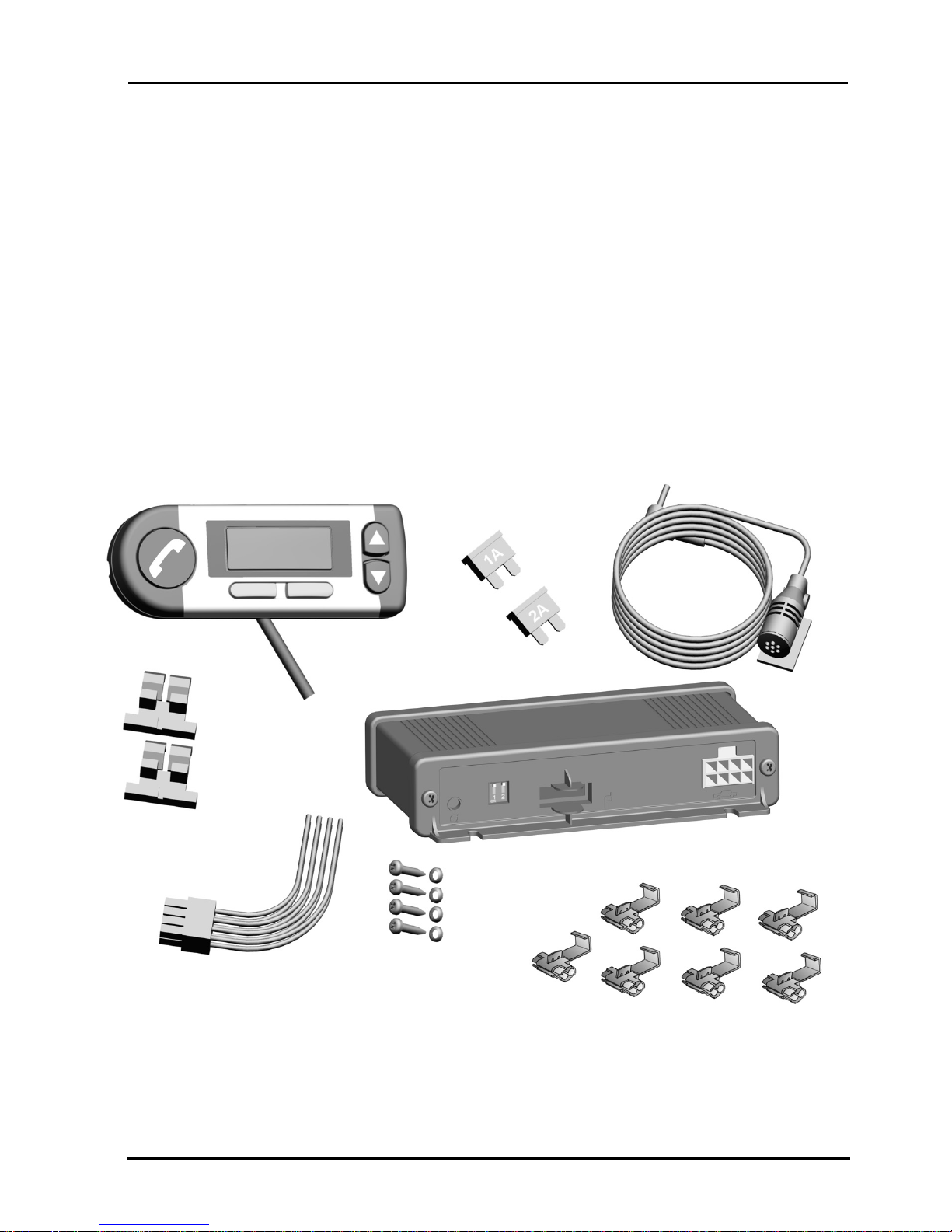
Parts List …………………………………………………………………………..... 5
Safety Precautions …..…………………………………………………..……….. 6
Installation Guide ....................................………………........................…........ 7
Required Accessory Items and Tools ......………………........................…....... 8
Getting Started .................................………………......................................... 8
Selecting the Mounting Positions ................……………….................….......... 9
Mounting the Microphone .......................................……………..................... 11
Mounting the Control Unit .........…………….................................................. 11
Mounting the Remote Control ............................................…………............ 12
Making the Electrical Connections to the Control Unit .........………..…......... 12
Power Connection ...........................................................…………...….......... 13
Audio Connection Type A .................................................…………............... 14
Audio Connection Type B ..................................……………........................... 14
Audio Connection Type C .................……………........................................... 15
Audio Connection Type D ....……………....................................................... 16
Connecting all Components of the VoiceCom 1000 TM System …..……..…. 16
Testing the VoiceCom 1000 TM System ....................…………………........... 17
Accessory Parts ..........................................................……………............... 18
Optional Accessory Parts ......................................……………..................... 18
Spare Parts ................................................................……………............... 19
Support ..................................……………...................................................... 19
Warranty .....................………………................................................ 19
Certifications .......………………..................................................................... 19
Changes .........………………......................................................................... 19
-3-

In
tr
od
uctio
n
Welcome
VoiceCom 1000™
Than
k
you
ve
ry mu
ch
f
or pu
rchasing
t
he
VoiceCom
1000™
with
voice co
nt
ro
l
fr
om ROSEN ENTERTAINMENT SYSTEMS (ROSEN)
. T
his Bl
uet
oo
th
®
hand
s-
free
mobi
le phone
car
kit
is
an
imp
o
rt
ant
cont
ribu
t
ion
to
ro
ad safe
t
y and
t
he
convenien
t
h
a
nds-free
use
of
your
mo
bile phone
whil
e
driving.
The VoiceCom 1000
™
systems offers
you th
e possibility
of opera
t
ing
dif
f
eren
t
mobile
phone
models
in
your
car
with
the
same
once
installed
univ
ersal
car kit.
This
is m
a
de possible
by
Bluetooth
®
Radio
t
echnolo
gy allo
wing
yo
u to
use most
Blue
to
oth
®
en
ab
led phon
es w
i
th
one
car
kit.
Fo
r operating convenie
nce an
d safe
t
y
wh
ile making or
receiving phone
calls in
th
e car
,
t
he
VoiceCom 1000
™
syst
em is f
e
at
urin
g int
er
a
ct
ive voice control. In
addition
you
can
assign any phone
number
to
an
emergency
call key
co
mbi
n
at
ion.
W
e
hope our unique
VoiceCom 1000
™
will prov
ide yo
u with
many
yea
rs
of
safe,
unt
roubled
an
d
conven
ient mo
bile
phone use
wh
ile driving,
enjoying
state
-of-the
-ar
t
design,
exce
llent
qu
alit
y
an
d un
mat
ched pe
rf
ormance
o
f
th
e
VoiceCom 1000
™
.
Introduction
Th
is in
st
allat
ion manual fo
r t
he
VoiceCom 1000™
co
nt
ain
s
all n
e
cessar
y
informa
t
ion required
to in
s
t
all th
e VoiceCom 1000™
s
ystem int
o your
ca
r.
Th
e
VoiceCom 1000™
syste
m
has bee
n design
ed f
or
easy in
stallation, ho
wever
ROSEN
strongly recommends
to have the sy
stem ins
t
a
lled
by a
pr
of
essional
inst
alle
r.
ROSEN
Limited Warranty
is void unl
e
ss
installed by
a
qualified
prof
essio
nal
installer.
Ple
a
se
visit
our
we
bsite
www.rosenentertainment.
com
fo
r a listing o
f
ROSEN
q
u
alifie
d pro
f
ession
al
installer
s ne
ar
you.
Th
e in
st
aller
may
also
provide you
wit
h
th
e
initi
a
l
tr
ain
ing on
t
he proper operation o
f
th
e
VoiceCom
1000™.
-4-

VoiceCom 1000™
Part
s Li
st
Parts List
T
he
pa
cking un
it sh
ould includ
e the fo
llow
ing
ite
m
s:
• Control
Unit - (1)
• M
ounting Sc
rews
and Wa
shers
for Control U
nit (4 sets)
- (2)
• Re
mo
te
Co
n
tro
l -
(3
)
• Micr
ophon
e with
Holder
- (4)
•
In
st
a
llat
ion
Ma
nu
al
•
In
st
allat
ion
Re
por
t
• Registration and W
a
rranty
Card
• ROSEN Limit
ed Warr
ant
y
Po
licy
• Ope
r
at
ing manual
-5-

Safe
ty Prec
aut
ions
Safety Precautions
Improper Installation:
VoiceCom 1000™
Th
e installation
of
t
he
VoiceCom 1000™
requires
special kn
owle
dge,
a
bilities
an
d tools. Improper
insta
llation may c
a
use
dam
a
ge
to the unit or to the
ve
hicle!
We
t
here
f
ore
str
ongly re
commen
d h
a
ving
the
in
st
allat
ion done by
a
pr
of
ession
al installer
.
THE ROSEN
LIMITED WARRANTY
IS VOI
D UNLESS
THE
VOICECOM 1000
™
IS INSTALLED BY
A
QUALIFIED
PROFESSIONAL INSTALLER
Person
a
l Injury:
In
appr
op
riate
places for
th
e in
st
allat
ion
of th
e VoiceCom 1000™
syste
m
may
c
a
use person
al inju
ry
in
a
cciden
t
s
or may dis
a
bl
e th
e saf
et
y equi
pme
n
t
o
f
th
e
vehi
cle! No
te
th
e dire
ct
ions
in t
he chapter
Installa
tion
!
When removing
coverings or
d
a
sh
boar
d part
s, sharp
tools may cause
personal
injuries
or
mat
eri
al
d
a
mage.
Use adeq
uate
to
ols an
d
remove parts c
a
refully.
Don'
t nick
, cut
or
pu
ll existin
g
car
w
iring
harn
esses.
Damage
to the
Airbag System:
A wr
ong pl
ace
se
lecte
d
for
t
he
inst
allat
ion
of
any componen
t
of
t
he
VoiceCom
1000
™
syst
em may cause d
a
mage
t
o
the airbag sy
stem or impa
ir the
operation o
f
th
e air
b
ag. Install a l l
compo
nen
ts ou
t of
rang
e of
action
of
the
a
i
rbag!
Damage
to I
n
sula
tio
n
of Wires:
Damage
d insul
a
t
ion
on any wir
e o
f
t
he
exist
ing ve
hicle wi
ring or
the wir
ing
of
th
e
VoiceCom 1000™
syst
e
m may
cause damag
e
t
o
th
e
un
it
, damag
e
to
the
electric
al sys
tem of the vehicle, and
may cause short-circuiting an
d fire.
All
wir
es should no
t
be pinched
or
nicked
an
d should
be
proper
ly f
ixe
d t
o
avoid
an
y
te
nsile str
ess or possible
d
a
mage by
chaf
ing!
Damage
by Polarity Rev
e
rsal or Short-Circuit:
In
correctly
co
nnected
wires m
ay
cause a
polarity revers
al
or short-circuit. This
will result in
severe damage
to the
equipment.
It is
esse
ntia
l
to dis
connec
t
the
c
a
r ba
tt
ery be
fo
re beginning
t
he elec
t
ric
al installatio
n
of th
e VoiceCom 1000™
s
yst
em!
-6-

VoiceCom 1000™
Inst
allat
ion
Guid
e
Da
mage of
Ca
r Com
ponents:
Drilling holes or using self-tapping
screws
when mounting the
VoiceCom
1000™
s
ystem
ma
y cause da
mage to
imp
o
rta
nt
vehicle co
mp
onen
t
s or
to
the
wiring. Mak
e sure
there is
enoug
h spa
ce
left
behind drilling holes
and
scre
ws
!
Effects on the Car's Electrical System:
Alt
hough
th
e VoiceCom 1000™
syst
em has
been designed
for minimum
radiatio
n
levels,
impr
oper
installation
o
f
co
mp
on
ents of
t
he
syste
m
may
infl
uence
t
he
elect
ronic eq
uipme
n
t
of th
e ve
hicle. Ple
a
se
not
e
the inst
ru
ct
ions
in th
e ve
hicle's
o
w
ne
r‘s
manu
al!
Da
mage Caused by
Wron
g Replac
ement
Pa
rts or Accessories:
Use o
f
replacemen
t
and acce
ssories
par
t
s ot
her
th
an
tho
se reco
mmend
ed by
ROSEN
my cau
se
damag
e
t
o
t
he VoiceCom 1000™
syst
em and voids
t
he
ROSEN
Limit
ed
Warr
ant
y.
Only use
replacemen
t
and
a
ccessories
pa
rts
listed
in
the
chapters Spare Part
s
and A
ccessory
Parts,
or
visit
ROSEN
we
bsit
e
www.rosenentertainment.com
fo
r fu
rt
he
r inf
or
m
at
ion
!
Pro
per Use:
T
he VoiceCom 1000™
is to be used
in cars only together
with a mobile pho
ne.
Installation Guide
The
followin
g in
st
allat
ion
instruct
ions ar
e no
t
me
ant
to
be
a g
uid
e f
or se
lf-
installation
, rather
t
h
an a sup
por
t
ing
docume
n
t
fo
r t
he pr
of
essional in
st
aller
.
Sho
uld you decide
to
in
st
al
l
t
he VoiceCom 1000™
syst
e
m yo
urse
lf,
wh
ic
h
w
ill
void
the ROSEN Li
mited
W
a
rranty
, please read
an
d fo
llo
w th
e installation
instruc
t
ions very c
a
refully an
d str
i
ct
ly obse
rve all saf
e
t
y prec
au
tio
ns.
I
m
proper Installa
tio
n
:
The installation of the VoiceCom
1000
TM
requires specia
l k
nowledg
e, abilities
and tools.
I
m
proper
in
stallation may
cause dam
age to the unit
or
to
the
vehicle!
We the
refore strongly recommend having
th
e
in
stallation
done by
a professiona
l installer.
-7-

Getting Started
Re
quired Acce
ssory
Ite
m
s and Tools
VoiceCom 1000™
To
per
f
or
m the
actu
al
in
st
allat
ion
, t
he f
o
llow
i
ng t
ools are r
equired:
~
Philips Screwdrive
r PH 1x80
~
Universa
l
Pliers
~
S
i
de-Cut
t
ing
Plier
s
~
Va
ria
ble
Speed Hand Drill
~
2
mm Drill Bit (M
etal)
~
9
mm
Wr
ench
~
Mult
imet
er or
Te
st
Lamp
~
Radio Re
moving
To
ols
~
V
ehicle
Sp
ecific
To
ols f
or
Re
moving
Cove
rings
~
Wire Straps
~
Degr
ea
sing Agen
t
such
a
s
Ru
bbing
Alcohol
Getting Started
Bef
ore yo
u start
wit
h
th
e inst
allat
ion o
f
th
e VoiceCom 1000™
make sure
th
at
all
p
a
rt
s as listed
in th
e Part
s List are pr
esent
. In order
to
f
ully oper
at
e t
he
VoiceCom 1000™
sy
stem
you will need the
followi
ng a
dditional parts
and
accessor
i
es, wh
ich
ar
e availab
l
e th
rough
ROSEN
aut
hor
ized
di
str
i
but
ors
an
d
de
ale
rs:
•
Wi
ring Harness:
Th
e
Co
nt
rol Un
it o
f
th
e
VoiceCom 1000™
s
yst
em
has
t
o
be conne
cted
to t
he
vehicle
wirin
g
har
ness for
pow
er, sou
nd and
ot
her
car
specif
ic in
te
rf
aces.
•
U
niversal Wiri
ng Harness:
In case there
is no Wir
ing
Harness available
fo
r a spe
c
if
ic car
,
ROSEN
of
fe
rs a
U
niversal Wi
ring Harness
which
may be
pu
rchased separ
a
t
ely
f
ro
m
aut
hor
ize
d
distr
i
but
ors
and
de
alers or
th
rough
ROSEN
we
bsite
www.rosenentertainment.com
, and follo
w th
e wir
ing
instructions
given in this Installation M
a
nua
l.
Af
te
r
hav
ing checked
an
d m
a
de
a
vailab
l
e all ab
ove men
t
ioned required
p
a
rt
s f
or
th
e installation
of
t
he VoiceCom 1000™
syst
e
m,
you
should look at
t
he
ve
hicle's o
w
ne
r's manu
al for
t
he
f
ollo
wing
it
ems:
•
Th
e vehicl
e'
s main
av
ailab
le
po
w
er source
mus
t
be no
min
a
l 12
V
D
C
wit
h
minu
s conn
ecte
d to
ground.
T
he VoiceCom 1000™
syst
em ope
rates
be
t
w
een 11
V
D
C
an
d
15
V
D
C.
-8-

VoiceCom 1000™
Se
lectin
g th
e Mo
un
tin
g Positions
•
Ch
eck if
t
he vehicle
'
s
installed
r
a
dio
has lin
e-in
and/or
mu
te
con
nect
or pins.
Properly
insta
lled
a
nd
using
the car
specific Wiring
Harness
or the
Universal
Wiring
H
a
rness
as
per the
ins
t
ruc
t
ions
of this
Insta
llation
Manu
al,
th
e
radio
will
be
mu
te
d
au
to
ma
tic
a
lly when receiving or
making
a
call.
If none of
t
hese conn
ecto
r pins ar
e availab
le
on
th
e r
a
dio,
you need
t
o
pur
chase
t
he
opt
ion
a
l
Radio Mu
tin
g
acc
es
sory as
listed under Optional
Accessory
Parts
of this
Installation Manual.
•
In the following cas
es
you will
ha
ve
to use
a
n
additional speak
er
for
conne
cting
to t
he VoiceCom 1000™
syste
m
:
»
If t
her
e are
no
radio
/sp
eake
rs installed
in
the
vehicle;
»
If t
he car radio
’
s installed sp
eakers are n
o
t t
o be used;
»
If
th
e c
a
r
rad
i
o'
s spe
ake
r
ou
tput
po
w
er exceeds 35
W
a
tt
s (
sine
-
w
a
ve
)
pe
r channe
l an
d th
e car
r
a
dio does
not
have
lin
e-in conn
ecto
r pins;
»
If
the
installe
d car radio
is oper
atin
g wit
h po
wer
ed sp
eake
r syst
ems and
th
e car radio
does no
t have line-in
con
nect
or
pins.
In any of such
ca
ses
a
n
Auxiliary Speaker o
f
no
min
a
l 5 W
a
tt
s an
d 4 Oh
ms
im
pe
da
nce
has
t
o
be sele
cte
d
an
d
purc
ha
sed,
as
list
ed under
t
he
Op
tio
n
a
l
Accessory
Pa
rts
of this
Ins
t
alla
tion
Man
u
al. To avo
id
acousti
c fee
db
a
ck
t
he
a
ux
iliary spea
ker has to
be mounted at
leas
t 32
inches (80 cm)
away from the
m
i
crophone a
nd should
not face it directly. For
proper installation of
the
Aux
iliary
Spe
a
ker
please re
fe
r to
t
he
installation
instr
u
ctio
ns
enclosed
with
t
h
is unit
.
Selecting the Mounting Positions
Perso
nal Injury:
Inappropriate pl
aces for the insta
llation of
the VoiceCom 1000™
system may
cause pe
rsonal
injury
in
accid
ents
or may disable
the safe
ty equip
m
ent
of
the
vehicle
!
When
remov
i
ng covering
s
or dashboard
parts,
sh
arp
tools may cau
s
e perso
nal injuries
or material
dama
ge. Use adequa
te
tools and remove parts carefully.
Don't nick, cut or pull existing car wiring harn
esses.
When selecting mounti
ng
loc
a
tions
f
or
t
he
var
ious
co
mp
onen
ts
o
f
t
he
VoiceCom
1000™
sys
tem,
check
if
t
he
cab
le leng
t
hs
all
o
w
eas
y conn
ect
ion o
f
a
ll
t
he
individual
co
mp
onen
t
s
wit
h
e
ach
o
t
her. Observe
in
ad
di
t
ion
t
he
f
oll
owi
ng
reco
mme
nd
at
ions be
fo
re deciding on
a pe
rmanen
t i
n
st
a
ll
a
t
ion lo
ca
ti
on:
-9-

S
elec
t
in
g the Mou
n
t
in
g Po
sit
ions
VoiceCom 1000™
Suitable Pl
aces for the Microphone:
•
When
th
e sound o
f
t
he driver
's vo
ice
can h
i
t t
he
micr
ophon
e wit
hou
t
ob
st
ru
ct
ions, and the
distance be
tw
een
th
e micr
ophon
e and
the
next
speaker
is at least 32 inches
(80
cm);
•
Near the rear view mirror;
•
Beside
s t
he driver
's su
n-viso
r;
•
On
th
e da
shbo
a
rd;
•
On
the steering col
u
mn;
•
On the car's A-pillar
Unsuitable
Place
s
for the Mi
crophone
:
•
Close to
th
e next
car speaker
(le
s
s th
an
32 inches
);
•
Unde
r t
he dashb
o
ard
;
•
Close to ve
nt
ilat
or
or
air-con
d
itio
ner ou
tle
t
s;
•
Where the sun visor will block the microphone
Suitable Places for the Control Unit
•
Inside
a ve
hicle specif
ic built-in cen
t
er console;
•
Behi
nd t
he pan
e
l of
t
he
cen
t
er console
on
th
e passe
nger side;
•
Behi
nd the low
er
d
a
shbo
ard
panel be
hind
th
e radio
Unsuitable
Place
s
for the Control Unit
•
W
i
thin
the
airbag a
rea of
action;
•
Unde
r t
he dashb
o
ard
w
i
thin the
leg or kn
ee are
a
;
•
On
to
p
of
th
e d
ash
bo
ar
d;
•
In th
e engine
comp
ar
tme
n
t
Suitable Pl
aces for the Remote Con
t
rol
•
On
t
he dashbo
ar
d, at
a
poin
t whe
re
t
he driver
can
see
it
clearly and access
it
easily
•
On
t
o
t
he cent
er console
be
t
w
een driver
and passeng
er
Unsuitable
Place
s
for the Remo
te
Control
•
W
i
thin
the
airbag a
rea of
action;
•
Ou
t
sid
e th
e driver
‘s
re
ac
h;
•
Any plac
e where there is
a pos
s
ibility
of head-imp
ac
t
-10-

VoiceCom 1000™
Se
lectin
g th
e Mo
un
tin
g Positions
Mounting the
Micr
ophone
The
re
is a self
-adh
esive tape
aff
i
xed t
o
the
re
ar
o
f
th
e micr
ophone holder.
T
he
se
lecte
d
moun
tin
g place mu
st
suit in size and shape
the
se
lf-adhesiv
e surface
of t
he
micr
ophone holder
. Th
e micro
phone
cable
must e
x
t
end up
to th
e pl
ace
of
moun
tin
g
t
he
Con
t
ro
l Unit
!
Ch
eck th
e be
st
ro
ut
ing
of
th
e micr
ophone
cable
a
nd po
sit
ion
th
e ca
ble.
Mak
e sure yo
u can
po
sit
ion
th
e mic
rophone
w
i
t
h
its
sp
eak
er opening facing
the
direction
of
speech
.
The
illu
stration shows a
possibl
e an
d pr
ef
erred
mo
un
tin
g
po
sit
ion.
Make sure the mounting
surface is free
of grease and
dust b
e
fore att
a
ching the
micropho
ne
holder.
Clean t he
design
a
ted area w
ith
a suitable
detergent such as rubbing alcohol.
Only
use
cle
a
ning de
te
rg
ent
s
t
hat do
not
dissolve plastics or
at
tack wo
oden
su
rf
ac
es.
Unsui
t
a
ble
a
gen
t
s
ar
e
cl
ea
ning
ben
z
ene,
ac
et
one,
t
urpen
t
ine,
tr
ichlor
oet
hylene or similar produ
ct
s.
Af
t
er
cle
a
ning pu
ll t
he
pro
t
ec
t
i
ve f
oil
off
the
adhesive
s
t
rip.
Hold
the
micr
ophone holder at
a d
i
st
ance of
a
few
millime
t
ers
over
th
e select
ed
Mounting
pos
i
tion.
C
heck the position ag
ain!
It will not be possible
to
co
rrect
the
posit
ion
on
ce t
he micr
ophone holder
is aff
ixed
!
If
yo
u are
sure
yo
u select
ed
the
corr
ect
posit
ion, place the
micr
ophone holder on
t
o
t
he se
lecte
d po
sit
ion
and
pres
s f
i
rmly. At
tach
th
e micr
ophon
e to
t
he
holder
and
alig
n it int
o
th
e dire
ct
ion
o
f
speech. Comple
te
th
e
rou
t
in
g an
d po
sit
ioning
o
f
th
e micr
ophone
cab
le.
Alt
ern
at
ivel
y t
he
micr
ophone may be
at
tached
to th
e sun
-
visor using
th
e clip
enclose
d with
the
micr
ophone.
Make su
re
t
he
micr
ophone
cable
does no
t
obst
r
uct
t
he
mo
ve
ment
of
t
he sun
-
visor.
Mounting the Control Unit
Damage
of
Car
Compon
ents:
Drilling hole
s
or using
self-
tapping screws
when mou
n
ti
ng th
e VoiceCom 1000
™
system
may
cause
damage
to impo
rtant vehi
cle
com
ponents or to the wiring
. Make
sure there
is e
nough
spa
c
e le
ft
behind drilling hole
s
and screws!
Man
y c
a
r manu
f
act
urers provide buil
t
-
in
cen
t
er consoles
f
or
a
r
a
nge
of
pas
senger
c
a
rs.
Th
ey can ea
sily
acc
ommod
a
t
e
t
he
Co
nt
rol Un
it
and al
l required
wi
ring.
-11-

S
elec
t
in
g the Mou
n
t
in
g Po
sit
ions
I
f
such
a
console
is no
t
avai
l
a
ble,
t
he
Control
Uni
t
should be moun
ted
behi
nd t
he r
a
dio
under
t
he da
shbo
ard
.
Car
e
fu
lly re
mo
ve th
e
consol
e
pa
nels
or
d
ashbo
ard
panel
s
an
d
de
ter
m
ine
a
sui
t
abl
e
mou
n
ti
ng
pos
it
ion.
Be sure that there
is at
least 2
¾
inches
(7
0 mm)
f
r
ee space be
hind the
Control
Unit
for
the
plug
-in
co
nnector
s
. Mark
screw
positions
and dr
ill t
he f
our mount
ing holes
with
a
2
mm
drill
. Using the
fou
r suppli
ed
metal screws with washers will
fix th
e
Contro
l Unit
in
it
s position.
VoiceCom 1000™
Mounting the Remote Control
Da
mage
to
the
Airbag System:
A w
ron
g place sel
ected for
the installa
tio
n
of any com
ponent of
the VoiceCom 1000™
System may
cause dama
ge to th
e airbag system or
impai
r the operation of the
airbag. Install any component
out of range
of action
of the ai
rbag
!
Hold the Remot
e
Con
t
ro
l at th
e sp
ot
w
her
e you wish t
o
mo
un
t it. The
re
is a
self-adhesive
st
ri
p on t
he rear of
t
he
o
f
t
he cont
ro
l unit
.
T
he
shape
an
d fo
rm of
the bearing surface mus
t
suit this a
dhesive
s
t
rip.
The ca
ble can be wired and
broug
ht
out
at
th
e rear of
th
e Remo
te
Co
nt
rol in
a variable
manner.
T
he
conn
ectio
n
cab
l
e must be
long enough
to
reach the Contro
l unit
.
Once you
h
a
ve
decided on
whe
re
to mo
unt
it, pu
ll
t
he pro
t
ec
t
i
ve film o
ff
t
he
ad
hesive str
i
p and
br
ief
ly bu
t fir
m
ly
pres
s th
e Re
mot
e Control
on
t
o
th
e moun
tin
g location.
Do th
is
c
a
refully
because it will
not be
possible to c
o
rrect the position la
ter.
Making the Electrical Conn
ections to the Control Unit
Damage
to I
nsulation
of Wire
s:
Damag
ed insulation on
any
wire o
f
the e
xisting
vehicle w
i
ring or the
wiring
of the
VoiceCom 1000™
system m
ay cause da
mage
to the
unit,
dama
ge to the electri
c
al sy
stem of the vehicle, and
may
ca
use short-circuiting
and fire.
All wires should
not
be
pinched or nicked and
should be
properly fixed to
avoi
d any tensile stress o
r po
ssible dam
age by
chafin
g!
-12-

VoiceCom 1000™
Po
wer
Co
nn
ectio
n
Damage
by Polarity Rev
e
rsal or Short-Circuit:
Incorrectly
con
nected wires may cause
a
polarity re
versal or
sh
ort-
circuit.
This
will
result
in
sev
ere
dama
ge to the
equip
m
ent. It is essential to di
sconnect the
car ba
ttery
before
beginning
the
electrical
installa
tio
n
of the
VoiceCom 1000™
syste
m
!
Plug
-and-p
lay e
l
ectr
ical co
n
nect
i
on is t
he pre
f
err
ed w
a
y of
making
t
he required
elect
r
ical
wir
ing
o
f
th
e VoiceCom 1000™
Con
t
rol Unit. The
car specific
Wir
ing
Har
ness available
f
r
om
ROSEN
as
a
n
ac
cessory part is specifically
designed for
yo
ur ca
r,
a
nd makes for an erro
r-
fr
ee
an
d fa
st e
lec
tr
ical co
nnec
tio
n
of
th
e
system
components
.
The
in
st
allat
ion
instr
u
ct
ions f
or
each
Wir
ing H
a
rness can
be
seen
at
ROSEN
w
e
bsit
e
ww
w.rosenentertainment.com
.
In c
ase of unavailability
of a vehicle
specific Wiring Harness, the Universal
W
i
ring Ha
rnes
s (av
ailable
as
access
ory part) should be us
ed a
n
d the
following
instructions followed c
a
refully:
Power Conne
c
tion
Do no
t cut
any
wi
re
s
of the
ve
hicle's
factory
installed
wiring
harne
sse
s! In most
ca
ses
it
voids the
manu
facturer's warranty!
C
u
t
t
he blue
wir
e o
f
th
e
Universal Wiring
Ha
rnes
s (p
os
itio
n 5
)
ap
prox
. 1 f
t
. (3
0
cm)
f
ro
m
t
he conn
ecto
r an
d conne
ct the
w
i
res ag
ain
w
ith a
f
use holder. Use
t
he
supplie
d cable
f
use holder,
an
d fir
m
ly make th
e conne
ct
ion
using
univer
sal
pliers.
Inser
t
th
e supplie
d 1 Amp
f
use
. Re
pe
at
t
he procedur
e w
i
th
t
he re
d w
ire
(p
ositio
n 2)
an
d inser
t
th
e supplied
2
Amp f
use.
Wit
hin
th
e car's wir
ing h
a
rnes
s t
o
th
e r
a
dio
locate
t
he
permanen
t
12
VDC cable
co
ming fr
om th
e car's
b
a
tt
ery.
Cu
t th
e
red
wire
of the Universal
W
i
ring Harness
to th
e
desired leng
th
and use a su
pplied
cable
con
nect
or
to
con
nect
it
to
t
he
permanen
t
12
VDC wire.
Lo
cat
e
t
he swit
ched 12
VDC po
wer
cable
co
ming from
the
ig
nit
ion
switch
and
repe
at
t
he same procedure
wit
h
the
blue
wir
e
of
t
he
Universal Wiri
ng Harn
ess. Lo
cat
e
t
he ground
wire of
the
car
'
s wir
ing
harn
ess
an
d con
nect
th
e bro
w
n w
ire
of th
e Univer
sal
Wir
i
ng Harness (p
osit
ion 1
)
to
it
using
a cable
conn
ecto
r.
Th
e connec
t
ion
of th
e cables
is sho
w
n
in
t
he
illustra
tion.
-13-

P
o
we
r Co
nnec
tio
n
VoiceCom 1000™
Audi
o Conne
c
tion Type A
If
your
car r
a
dio has line-in
and
mu
te
pins, you
ar
e
able
t
o
make
t
he
best
pe
rf
or
min
g
audio
conne
ct
ion.
Con
s
ult
t
he
r
a
di
o's o
w
ne
r's manu
al
! L
o
cate
t
he
line
-
in
posit
ive
(+) pin
on t
he r
a
dio connec
t
or
an
d conn
ect t
he
purp
le w
ire
(p
ositi
on
4) of
t
he
Universal Wiring
Harn
es
s to it.
Yo
u may
h
a
ve to
use a radio
sp
ecific connector, which
is
ava
ilable
through specialist shops. Repeat the
procedure
f
or
t
he
line
-
in ground pin usin
g t
he green
wire
(po
s
it
ion 7
)
. F
i
nally
conn
ect t
he
mut
e pi
n of
t
he r
a
dio
with
th
e yello
w wir
e
(po
s
itio
n 6) o
f
t
he
Univers
a
l W
i
ring Ha
rness. See the illus
t
ration. With this connection type, the
radio
mut
es during
an in
co
ming
or ou
tg
oing
phon
e call and
t
he
au
dio
is
tr
ansmitted t
hroug
h th
e car
'
s bu
ilt-in speaker
syst
e
m.
Audi
o Conne
c
tion Type B
You
should choos
e th
is t
ype
of audio
conn
ectio
n
if
your
car ra
dio
has
no li
ne-in
cap
abilit
y, a
nd your r
a
dio
spea
ker
outpu
t po
wer
does
not
exceed 35
Watts
per
cha
nnel.
Fo
r
best
audio
tran
smi
ssion
o
f
the mo
bile phone‘s sound
it
is
-14-

VoiceCom 1000™
Po
wer
Co
nn
ectio
n
recomme
nded to use the
fro
nt passenger
side
s
peak
er
be
cau
se of
a
lo
w risk of
audio
feedb
ack,
and it is ge
nerally ea
sy to
hear. Loca
t
e the
posi
t
ive wire
from the
radio
'
s wirin
g
ha
rnes
s to
th
e pa
ssenger
side
spe
aker
(see
th
e ra
dio
own
e
r's
manu
al). C
u
t this
wir
e
appr
ox. 1 f
t
(30 c
m
) fro
m
the
conn
ector
.
Cut t
he white wire
(position 3
)
of
the Univer
sal
Wir
i
ng Harne
ss to
the
desired le
ngth
and
conne
ct it
to
the short end of
the previously cu
t sp
eake
r wir
e, us
ing a s
uppli
ed ca
ble connec
tor.
Repea
t th
e procedure using
the
purpl
e wi
re (p
ositi
on 4
)
of
the
Univ
ersal
Wi
ring
Harness a
nd connec
t it t
o
the
long
end of
the
previously
cut
speak
e
r wire.
Loca
t
e the n
ega
tive w
i
re from
th
e ra
dio's
wiring h
a
rn
ess to th
e pas
senger
side
spea
ker
(se
e
the
radio ow
ne
r's m
a
nua
l).
Cu
t this w
i
re app
rox.
1
ft (30 cm) from
the
connector. Cu
t the black wire (po
s
itio
n 8) o
f
th
e Univers
a
l Wirin
g
Harness
to the
desired leng
th
an
d conn
ect it
to
the
shor
t en
d o
f
the
previously
cut sp
eake
r
wire,
using
a supplied cab
le connector. Repe
at the p
rocedure us
ing the g
ree
n wire
(pos
ition
7) of the
Univer
sal
Wiring
Harness
and
conne
ct it to
the
long
end
of the
previously cu
t
spea
ker w
ire. No
w
the
p
assen
ger side
speak
er
is conn
ected
throu
gh
the
VoiceCom 1000™
Con
t
rol Un
it.
Finally
con
nect the
mu
te
pin
of
the
ra
dio
with
th
e yello
w w
i
re (p
osition 6)
o
f
th
e Univ
ersa
l
W
iring
Harn
ess.
S
ee
the
illu
stratio
n.
With
this
conn
ection type, the
radio
mutes
during an
incom
ing or ou
tg
oing phone
call an
d
the audio
is trans
m
itte
d throug
h the ca
r's
passe
nger s
peak
er.
Audio Connection Type C
In
case
your
car
r
a
dio h
a
s
no
mu
te-p
in, ROSEN
of
fe
rs
an
opt
ion
a
l
a
ccessory
Ra
dio
Muting
un
it
,
which
allo
ws mut
ing
of
th
e car r
a
dio
‘
s spe
a
kers,
whe
n
a
ph
on
e call is made
or received.
You
can
f
ind
de
t
a
ils and the conn
ectio
n
-15-

P
o
we
r Co
nnec
tio
n
VoiceCom 1000™
diagr
a
m o
f
t
h
is unit
on
ROSEN
website
www.rosenentertainment.com
as
well as
how
you ma
y purchas
e this accessory
unit.
Audi
o Conne
c
tion Type D
Sho
uld
you
h
a
ve t
o
use an
ex
t
ern
al sp
eaker fo
r t
he audio
o
f
t
he mob
ile phone
as r
equired
wh
en
th
e cond
itio
ns as me
nti
one
d in t
he se
ctio
n 'Ge
tt
ing
Star
ted,
"
th
e aud
io connec
t
ion
to
t
he ex
ter
n
al spe
a
ker is made
wit
h
t
he purple
an
d
gree
n wir
e
s (p
ositio
ns 4 and 7
)
of the Universal Wiring Harnes
s. See
illustration.
W
i
th this
connec
t
ion ty
pe the radio is no
t muted
during an inc
o
ming
or
ou
tg
oing
ca
ll exce
pt
w
hen
t
he
Radio Muting unit is
ins
t
alled.
Connecting all Components
of the VoiceCom 1000™
System
Aft
er
mount
ing all t
he compo
nen
t
s
and p
er
f
or
ming
the electrical wir
ing
, t
he
co
mpo
nents are conn
ecte
d to
t
he
Co
nt
rol
Unit
as fo
llows:
~
Inse
rt
th
e micr
ophone male pl
ug
int
o
t
he micro
phone
jack
~
Inse
rt th
e main
connec
t
or pl
ug
f
r
om t
he Remo
te
Co
nt
ro
l (p
in
connec
to
r)
in
to
t
he Con
t
rol Un
it
and tig
h
t
en
the securing
screws
-16-

VoiceCom 1000™
Po
wer
Co
nn
ectio
n
~
Conn
ect
th
e vehicle spec
if
ic Wir
ing
Harne
ss
to
th
e Co
nt
rol
Unit
,
th
e
car
radi
o and car wiring
harness as pe
r
inst
ru
ct
ions o
f
t
he vehi
cle specif
ic
Wir
ing
Harn
ess,
or
~
Inse
rt the
Univ
ersa
l Wir
i
ng Harnes
s int
o
its p
o
siti
on
on th
e Con
t
rol Unit
Testing t
he VoiceCom 1000™ System
Once
the mechani
cal
a
n
d electri
cal
ins
t
alla
tion
is co
m
ple
ted
,
it is
tim
e
to
t
es
t
t
he
functionality
o
f
th
e
VoiceCom 1000
™
syste
m.
Th
e test for corre
ct
functioning is
only
possible
when the system
has
been connected
to
a
co
mp
at
ible
Bluetooth
®
phone
.
Please
re
fer
to th
e relevan
t
se
ct
ion
in t
he Owner’s
manu
a
l
t
o
f
ind ou
t
ho
w
t
o
proceed.
Te
st
pl
ac
in
g an
d receivin
g cal
ls,
the m
u
ting funct
ion
and
the audio leve
l. It is im
po
rtan
t
to test the
inte
lligibility of
yo
ur voice w
h
en
m
a
king
a call. Th
is is
depende
nt on
the
micro
phone se
nsitivity
an
d th
e di
stan
ce
be
twe
en
the
micro
phone
an
d th
e calle
r.
2 dip s
w
i
t
ches on
t
he
Con
t
rol Un
it
se
t
the
m
icrophone
se
nsitivity.
If
the
caller o
n
th
e
othe
r end
find
s
your voice volu
me
t
oo lo
w
wi
th
t
he
f
act
ory se
ttin
g
s of
the
dip sw
itches,
you
m
a
y be
ab
le
to
increase
th
e
se
nsitivity
by
ad
justing the
di
p sw
itch
es
as show
n in
the
illustratio
n
.
P
l
ease no
te,
that
increasing
th
e
m
icrophone sens
itivity
increases the
risk of irrit
a
ting
echoes.
If yo
u are
satisfie
d w
i
th
th
e system
and ca
bles
with the
wire
straps to avoid
irritating
r
a
ttle and g
r
ad
ual lo
osening
of
the
conne
ction
s
. M
a
ke sure no
w
ires
or
cables
are p
inched or ex
hibit unw
ante
d
ten
s
ile stress. Replace
a
ll
p
a
nels
a
nd
coverings in
t
o
t
he origin
al
st
a
t
e usin
g t
he
origin
a
l
ha
rd
w
a
re
an
d
ap
prop
riate tools.
Co
ng
ra
tu
l
a
t
ion
s!
You
ha
ve success
f
ully
co
mp
le
te
d
t
he in
st
allat
ion
of
th
e
VoiceCom 1000™
!
No
w y
o
u should take a little time
to get
fa
miliar with its operation.
Be
fore using
your
h
a
nds-fr
ee VoiceCom 1000™
syst
em on
t
he
ro
ad, make
some
phone
calls
in o
rder
to
find
ou
t t
he
opt
imum con
d
it
ions f
or volume and dire
ct
ion o
f
speech.
-17-
0dB3dB 6dB9dB

Ac
cessory Parts
VoiceCom 1000™
Ne
gative E
ffects
on Road
Safety: You
are now
th
e proud
owne
r of
the most
advanced ha
nds-free
mobile
phone
sy
stem a
nd wi
ll have a
safe
and
very conven
ient wa
y of
operating a mobile
phone in
the
car,
ho
wever, talking on
the p
hone
while
driving
re
duces y
our co
ncentration! T
h
is
may
ca
use
dangerou
s
situations
on
the road
.
Also
in
hands-free mode you
should
draw you
r m
a
in attention to
the traffic. In complex
and da
ngerous
traffic situ
ati
ons
you should
refrain from using your mobile phon
e!
Accessory Parts
To
succes
sf
ully inst
all an
d oper
at
e
the
VoiceCom 1000™
syst
e
ms you must
have s
eve
ral a
ccessory parts
wh
ic
h ar
e of
fe
red
by
ROSEN
either
th
rough
author
ize
d di
str
i
but
ors,
dealers and
retailers.
• Wiring Harness
A var
i
et
y of
vehicle
specif
ic
Wir
ing
Ha
rnesses are av
ailable from
ROSEN
distr
ibu
to
rs
an
d dealer
s
. Visit ROSEN
we
bsite
www.rosenentertainment.
com
fo
r a
co
mplete
listing of
av
ailable W
i
ring Harn
esses.
As
new cars arrive,
this lis
t
wil
l be u
pdat
ed.
• Uni
versal
Wiring
Harn
ess
Th
is wir
i
ng har
ness should
be used
if
t
here
is no specif
ic Wir
ing
Harn
ess
available
fo
r
your car. It is supplied
including
th
e
required conn
ecto
r hard
ware
a
n
d fuses.
Optional Accessory Parts
A v
a
riety of optional accessories
to
e
nhance
t
he
fu
nctio
n
of
your
VoiceCom
1000
™
syst
em ar
e available th
rough
ROSEN
au
th
orized distribu
to
rs, de
ale
r
s
an
d re
tailer
s
.
• Radio Mu
tin
g
Th
is un
it en
ab
les th
e fu
nctio
n
'r
adio mut
e
' while
dialing o
r rece
iving a
pho
ne cal
l
an
d
is
int
ended
t
o be used
whe
n
t
he in
st
al
led
radio
does no
t
have
mute
and
line
-
in pins.
• Acce
ssory
Speaker
Use t
his
spe
aker
wh
en
the
cond
itio
n '
Audio
Con
nec
tion
Typ
e
D' h
as
to b
e chosen.
-18-

VoiceCom 1000™
Su
ppo
rt
Spare Parts
•
Micr
ophone
•
Control Un
it
•
V
ehicl
e S
pec
ific
Wir
ing H
a
rness
•
Universal Wiri
ng Har
ness
•
Scre
w
K
i
t
Support
Product
assistance
is
availab
l
e
by
e-mail:
techelp@rosenentertainment.com
I
f
you like
to
sp
eak
t
o
a
ROSEN
technical
suppor
t re
presen
t
a
tiv
e,
pl
ea
se
call on
wee
kd
a
ys be
twe
en 8
am and
5 pm p
a
cif
i
c t
i
me ROSEN
hotline:
(888) 883-2790
. One of our customer support
representatives
will be
gla
d
to
assist you. Be prep
ar
ed
t
o
answe
r
t
he f
ollo
wing
ques
t
ion
s: th
e typ
e
of
cr
adle
an
d mobile
pho
ne you are
usi
ng wit
h your
VoiceCom 1000™
syst
em,
w
ho
in
st
alle
d
th
e
VoiceCom 1000™
sy
ste
m
,
an
d w
hen
it
w
as
ins
t
alle
d.
Warranty
Please re
fer to
t
he
sep
a
r
a
te
ly att
a
ch
ed ROSEN
Limit
ed
Warr
a
n
t
y.
Certifications
The
VoiceCom 1000™
me
et
s
th
e require
m
ents of
t
he
EMC
Dire
ct
ive 89/
336/EEC 'Elec
t
romagnetic Co
mpatibility'.
'e
1' type
approval
is accor
din
g to
the
EMC Dire
ctive
72/245
/EEC (95/54
/EC)
'Su
ppression
of
Radio
Inte
rf
erence
Pr
oduced
by Spar
k-Ign
i
tio
n
En
gines Fit
t
ed
t
o
Mo
to
r Veh
i
cles'.
Changes
As
a
result
of tec
h
nical
progress
a
ll
information and illustrations
of this
In
st
allat
ion
Manu
al ar
e subj
ect t
o
mo
di
f
i
cati
on. ROSEN
re
se
rves all rig
h
t
s
to
make
ch
an
ges
to
th
e product. Repr
intin
g
an
d reprod
uctio
n, in
part or in
fu
ll,
of
th
is Ins
t
alla
tio
n
Man
u
a
l
is no
t pe
rmitte
d
w
i
th
ou
t ex
press
w
ri
tte
n
consen
t
.
-19-

Visit us at
www.rosenentertainment.com
© ROSEN
.
All
righ
t
s reserved. Rosen Entertainment Systems, LLC and VoiceCom 1000
™ ar
e
tr
a
de
m
a
rks
o
f
ROSEN
.
P/N
9100585
Table of contents