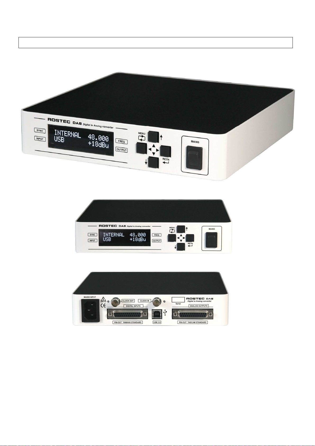
DA8 Digital to Analog Converter
5
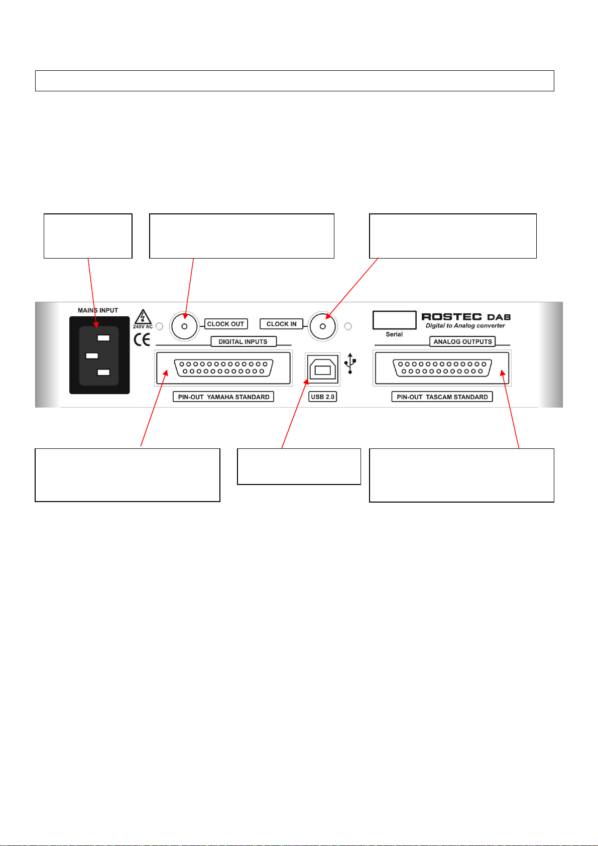
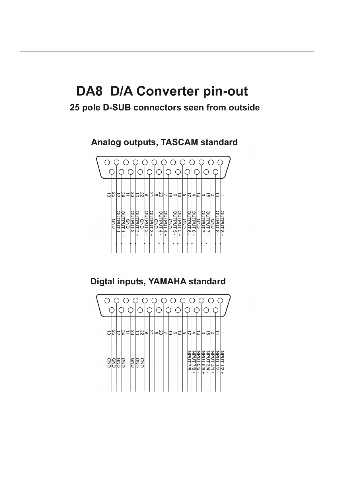
Analog outputs
The DA8 has eight analog audio outputs on the standard
25 pin D-sub connector at the back panel. The connector
follows the TASCAM DB-25 industrial pin-out standard.
The analog outputs are intended for use with active
control room monitors, featuring high performance
balanced floating industrial buffers, able to handle any
impedance from 600 ohm to infinite.
The buffers are true floating, which means that their
outputs are not referenced to ground, but is configured
as the difference between the negative and positive
terminals.
The outputs are normally used in balanced mode, but
can be configured to run in unbalanced mode. When
running in unbalanced mode, the negative terminal
MUST be connected to ground.
The analog output level can be selected at the front. The
nominal output level is +18 dBu at 0 dBFS, which is the
official EBU standard.
The +10 dBu setting is optimal for use with standard
(vintage) equipment. Older equipment has a 0 VU level
which corresponds to +4 dBu electric level. Setting the
maximum digital level to +10 dBu leaves 6 dB of extra
headroom for peaks above 0 VU. This setting provides
an operating level that brings out the best of most
vintage equipment.
Clock sync input and output
The DA8 has input and output for clock synchronization
on standard BNC connectors at the back.
The input is 1.5 kohm ( i.e. not terminated ) and the
output clock is 75 ohm 5 Volts, TTL compatible.
The clock input features a high-speed comparator with
hysteresis and a "sweet spot" detector, which performs
an accurate auto-slicing of the input.
This means that the circuit automatically chooses the
most useful part of the input signal, thus being able to
clean-up and reconstruct a ringing and noisy input clock
into a perfect output clock used to internally synchronize
the unit.
The unit is built with sync safety in mind. It always uses
the internal low jitter oscillator as the master clock for all
internal digital signals, and it always uses the master
clock oscillator to generate the output clock.
When it locks to an incoming clock, it continues to use
the internal oscillator as the master clock, but it gently
adjust the oscillator frequency to match the frequency of
the incoming signal, creating a phase lock between clock
input and clock output.
When the incoming clock signal is lost or discontinued,
the master clock oscillator gently glides back to its
internal reference, and continues to generate sync
signals without disruption. Thus, there are never gabs or
disturbances of any kind when the clock sync is lost and
re-established.
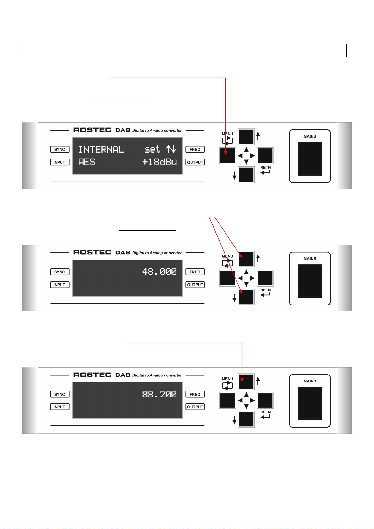
The unit works as an excellent clock reference generator
for a studio setup. In AES mode, the output clock
frequency is manually controlled at the front panel with
the arrow buttons. In USB mode, the output clock
frequency is controlled by the Work Station or the DAW.
The output clock accuracy is typically +/-2 ppm, and the
pulse shape of the long-haul output buffer is close to
theoretically perfect, with impressive jitter specifications,
steep rise time and no ringing, even with long cables.
Power Supply
The power supply is pure analog, with an oversized
toroidal transformer and low noise linear regulators.
This configuration creates an electromagnetic quiet
environment, free from the usual radiation pollution from
a switch-mode power supply.
A switch mode power supply generates strong repetitive
electromagnetic pulses that travel through air and sharp
current pulses that travel through the ground system.
When this pollution hit the analog circuitry, it disrupt the
smooth operation of the circuitry by pressing the
amplifiers into slew-rate-mode momentarily
But what is slew-rate-mode?
It is when an amplifier is presented with a signal, that
moves faster that the amplifiers maximum speed
capability. It then tries to “slew” as fast as it can, to cope
with the signal. When the amplifier is in this mode, it
cannot process any further information, it is in fact
blocked from reproducing incoming audio signals.
This happens in short durations, when the pulses from a
switch mode power supply hit the circuit.
The result is that 60.000 a second the analog circuit
looses, in small intervals, the ability to reproduce audio,
and this is in fact the main reason why audio products
with switch mode power supplies sound harsh, flat and
lifeless, with a degraded ability to process details and
depth in the audio.
DA8 maintains a clean electromagnetic environment in
the box, and the reward is a natural, pleasant, open and
detailed sound.