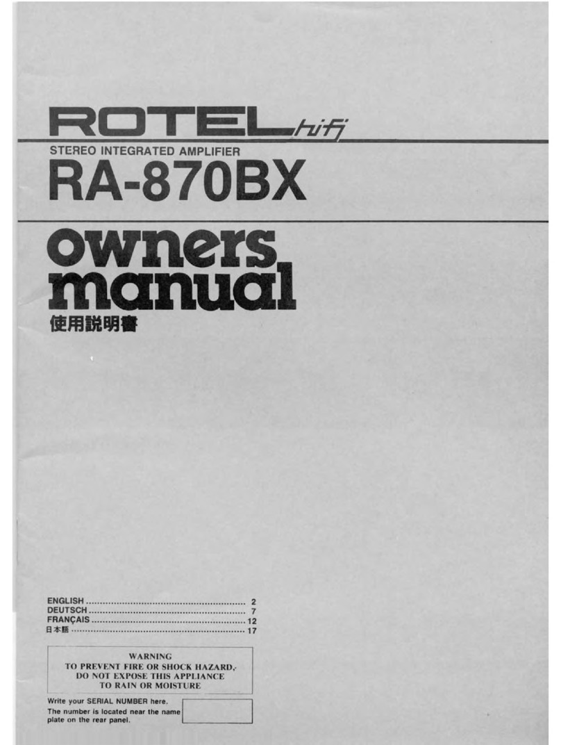
Rotel RA-935BX User manual

STEREO
INTEGRATED
AMPLIFIER_
RA-935BX
owners,
manual
j
i
ENGLISH..
DEUTSGH.
FRANQAIS
WARNING
TO
PREVENT
FIRE
OR
SHOCK
HAZARD,
DO
NOT
EXPOSE
THIS
APPLIANCE
TO
RAIN
OR
MOISTURE
Write
your
SERIAL
NUMBER
here.
The
number
is
located
near
the
name
plate
on
the
rear
panel.

©
Volume
Control
Used
to
regulate
the
volume
level.
Turn
clockwise
to
increase
the
level
and
counterclockwise
to
reduce
it.
The
control
permits
either
the
combined
or
the
separate
adjustment
of
the
left
and
the
right
channels.
Normally
turn
the
dual
concentric
knob
as
one
for
the
combined
adjustment.
When
it
is
necessary
for
the
separate
adjustment
of
each
channel
due
to
unbalanced
sound
levels
between
both
channels,
hold
the
front
part
of
the
knob
with
one
h
and
and
turn
the
rear
part
of
the
knob
independently.
Due
to
the
high
quality
material
and
construction
used
on
the
volume
control
for
sound
quality,
the
sound
level
will
not
rise
sharply
at
low
settings.
Normally,
the
control
is
recommended
to
be
set
between
11:30
to
2:00
o’clock
position
with
other
Rotel's
equipments
connected,
but
a
finite
adjustment
will
depend
on
the
sensitivity
of
your
speakers.
©
Recording
Selector
Permits
choose
any
input
connected
to
the
unit
and
feed
it
directly
to
the
TAPE
1
and
TAPE
2
outputs
on
the
back
of
the
unit
for
recording
the
selected
input.
However,
note
the
TAPE
1
input
can
be
recorded
by
the
TAPE
2
output,
but
the
TAPE
2
input
cannot
be
recorded
by
the
TAPE
1
output.
It
is
possible
to
record
one
source,
e.g.,
CD
or
TUNER,
while
listening
to
a
different
source
such
as
AUX.
When
not
recording,
ensure
to
set
the
selector
at
the
center
OFF
position
to
cut
off
the
circuit
completely
from
the
signal
path.
©
Listening
Selector
Allows
choose
any
input
connected
to
the
unit.
The
selector
operates
independently
from
the
Recording
selector
above,
so
you
can
listen
to
one
source
while
recording
another
different
source.
WORDS
ON
OPERATIONS
Precautions
1,
Before
commencing
operation,
check
to
see
if
all
connections
are
properly
made.
2,
Always
ensure
to
set
the
Volume
control
to
the
minimum
position
before
turning
on
the
Power
switch.
3,
Make
sure
the
Recording
selector
is
at
the
OFF
position
when
listening
to
any
source
and
not
recording.
Tuner
Reception
1.
Set
to
the
TUNER
position
on
the
Listening
selector.
2.
If
possible,
turn
your
tuner's
power
off
when
not
operating
it.
Although
crosstalks
are
held
to
minimum
by
the
circuit
design,
this
is
the
perfect
way
to
cut
off
the
signal
from
the
radio
reception
bleeding
through
to
the
other
inputs
connected
to
the
main
unit.
Operating
CD
Player
1.
Set
to
the
CD
position
on
the
Listening
selector.
2.
Read
the
instruction
manual
of
your
player
carefully
to
maximize
the
full
potential,
3.
Using
higher
quality
interconnecting
cords
between
your
CD
player
and
the
amplifier
may
often
improve
sound
quality.
Tape
Deck
Playback
1.
Set
to
the
TAPE
1
or
TAPE
2
position
on
the
Listening
selector
depending
on
which
input
your
tape
deck
is
connected.
2.
Use
only
a
good
quality
cassette
tape
deck
(in
terms
of
sound
quality)
or
a
DAT
deck,
etc.
for
maximizing
the
full
potential
of
the
amplifier.
3.
Using
higher
quality
interconnecting
cords
between
your
tape
deck
and
the
amplifier
may
often
improve
sound
Recording
with
Tape
Deck
1.
Set
the
Recording
selector
to
any
input
you
wish
to
record,
and
proceed
the
recording
with
your
tape
deck
connected
to
the
TAPE
1
or
the
TAPE
2
outputs.
If
you
have
two
tape
decks,
you
can
only
record
the
TAPE
1
inputs
with
the
TAPE
2
outputs.
The
TAPE
2
inputs
cannot
be
recorded
by
the
TAPE
1
outputs.
2.
During
recording,
operation
of
the
Volume
control
have
no
effect
on
the
recorded
signal
being
fed
to
the
TAPE
1
or
TAPE
2
outputs.
3.
You
may
monitor
recording
signals
by
setting
the
Listening
selector
to
the
same
input
as
the
Recording
selector.
For
example
if
you
are
recording
CD,
set
the
Listening
selector
to
CD.
Dubbing
When
two
tape
decks
are
connected,
you
can
dub
(tape-
to-tape
copy)
one
tape
deck
to
the
other
tape
deck.
Note
the
dubbing
can
only
be
done
from
the
deck
connected
to
the
TAPE
1
input
to
the
other
deck
connected
to
the
TAPE
2
output.
HUM
AND
NOISE
In
any
high
fidelity
installations,
hum
may
be
caused
by
the
interconnection
of
turntable,
tuner,
amplifier
and
speakers
as
the
result
of
wiring,
different
grounding
or
locations
of
components.
If
hum
is
experienced
with
your
unit,
disconnect
everything
but
the
speakers
from
the
unit,
Plug
in
the
turntable
and
if
hum
or
howling
appears,
move
it
away
from
the
speakers
as
much
as
possible.
Note
hum
may
also
be
induced
by
defective
cable
connections
or
by
running
the
cables
too
close
to
strong
AC
field.
When
your
unit
picks
up
noise
during
the
reception
of
broadcasts,
causes
are
mostly
due
to
external
objects
such
as
fluorescent
lamps
and
house
appliances
using
motor
or
thermostat,
or
others
than
may
induce
noise.
Either
relocating
the
unit
away
from
the
noise
sources
or
using
an
improved
outdoor
antenna
may
readily
resolve
the
problem.
In
the
event
you
cannot
find
the
cause,
consult
your
dealer
or
a
qualified
electrician.

DO
SWITCHES
AND
CONTROLS
0
Speaker
Remote
Button
0
Power
Button
Press
the
button
to
activate
the
speakers
connected
to
the
Press
this
button
to
turn
on
and
off
the
unit.
REMOTE
speaker
terminal
posts
on
the
back
panel.
Release
_
the
button
to
cut
off
the
sound
from
the
remote
speakers.
©
Power
Indicator
Glows
when
power
is
turned
on
with
the
power
button.
(|)
Phones
Jack
Plug
your
headphones
to
this
jack,
making
sure
it
has
the
correct
type
connector.
For
private
listening,
if
your
speakers
are
connected
to
the
DIRECT
speaker
terminal
posts
on
the
back
panel,
you
have
to
disconnect
the
speakers
off
the
terminal
posts
to
cut
off
sound
from
the
speakers;
however,
if
your
speakers
are
connected
to
the
REMOTE
speaker
terminal
posts,
deactivate
the
Speaker
Remote
button
to
cut
off
sound
from
the
speakers.
Hence,
if
you
are
frequent
user
of
the
headphones,
you
may
wish
to
connect
the
speakers
to
the
REMOTE
terminal
posts
all
the
time.
CONNECTING
COMPONENTS
COMPACT
DISC
PLAYER
VIDEO
CASSETTE
RECOROER
RIGHT
LEFT
RIGHT
LEFT
DIRECT
SPEAKERS
REMOTE
SPEAKERS

ENGLISH
A
WORD
FROM
ROTEL
Rotel
take
this
opportunity
to
thank
you
for
choosing
our
equipment
for
your
home
entertainment.
Rotel
equipment
represents
a
very
high
state
of
the
art
in
sound
reproduction,
as
the
result
of
our
everlasting
determination
to
achieve
the
truly
hi-fi
performance.
Please
enjoy
the
sound
Rotel
have
created
for
many
years
to
come.
To
make
sure
you
get
the
most
out
of
your
equipment,
please
read
this
owner’s
manual
carefully
before
your
attempt
any
connections.
BEFORE
CONNECTIONS
1.
Place
for
Installation
Ensure
to
place
the
unit
in
a
flat
surface
where
it
is
free
from
humidity,
vibration,
high
temperature
and
not
exposed
to
direct
sunlight.
Also,
be
careful
not
to
place
the
unit
in
a
highly
enclosed
area
without
adequate
ventilation
around
the
unit.
Do
not
block
the
ventilation
openings
at
the
top
and
the
bottom
of
the
unit
to
prevent
excessive
heat
built
up.
2.
Electrical
Requirements
Your
equipment
has
been
designed
to
be
powered
by
the
local
AC
voltage.
Check
the
setting
of
your
unit
by
looking
at
the
rear
panel
name
plate.
Never
try
to
plug
the
unit
into
an
outlet
of
higher
voltage,
as
this
causes
a
serious
fire
hazard.
Consult
your
dealer
if
in
doubt.
3.
Connecting
the
Power
Cord
Always
handle
the
power
cord
with
care.
Ensure
to
connect
the
cord
to
the
household
wall
outlet.
When
plugging
and
unplugging
make
sure
the
power
switch
on
the
unit
is
turned
off.
4.
Do
not
Open
the
Cabinet
There
are
no
user-serviceable
parts
inside
the
cabinet
of
the
unit.
Do
not
attempt
to
open
the
cabinet
or
tamper
with
the
internal
components.
If
water
or
foreign
object
falls
inside
the
unit
by
accident,
disconnect
the
power
cord
immediately
and
consult
a
qualified
electrician
or
your
dealer.
5.
Cleaning
Your
Unit
If
your
unit
becomes
dirty,
wipe
it
gently
with
a
soft,
dry
cloth.
Never
use
solvents
of
any
kind.
CONNECTIONS
1.
Connecting
Components
The
illustration
shows
what
audio
components
you
can
connect
to
the
rear
panel
of
the
unit
and
how
they
should
be
properly
hooked
up
via
RCA
type
pin
cords.
Ensure
that
the
left
and
the
right
channels
are
correctly
matched
between
the
RCA
type
sockets
of
the
unit
and
those
on
the
components.
2.
Connecting
Speakers
a)
U
s
e
speakers
with
impedance
ratings
of
4
to
8
ohms.
However,
if
you
wish
to
hook
up
2
sets
(pairs)
of
speaker
systems
and
drive
both
sets
simultaneously,
ensure
each
speaker
is
rated
8
ohms
minimum.
Never
connect
speakers
with
lower
impedance
than
8
ohms
in
this
case.
The
speaker
impedance
is
indicated
on
the
back
or
in
the
instruction
manual
of
the
speaker.
b)
Do
not
use
speakers
that
have
very
high
capacitive
load,
say,
over
0.1
microfarads,
as
it
may
cause
a
damage
to
the
power
amplifier
section.
Normally,
most
speakers
are
low
capacitance
type,
but
there
are
a
few
which
do
have
excessively
high
capacitance.
c)
Use
proper
speaker
cords
normally
your
dealer
will
recommend,
with
as
low
capacitance
content
as
possible.
The
speaker
terminal
posts
provided
on
the
back
of
the
unit
can
also
take
banana
plugs.
d)
If
connecting
the
speaker
cords
directly
with
the
bare
wire
ends,
suggest
you
strip
about
1
cm
of
the
insulation
shield
cover
from
the
ends
of
the
speaker
cords.
Twist
any
exposed
strands
tightly,
and
insert
the
ends
properly
to
the
terminal
posts.
e)
The
DIRECT
terminal
posts
are
recommended
for
the
best
sound
quality
possible
from
the
unit
in
the
“straightpath
M
route
bypassing
the
headphone
circuit.
The
sound
from
the
speakers
connected
to
the
DIRECT
terminal
posts
will
not
be
affected
by
the
Speaker
Remote
button
on
the
front
panel.
However,
if
you
wish
to
listen
to
your
headphone
privately,
connect
your
speakers
to
the
REMOTE
terminal
posts
and
use
the
Speaker
Remote
button
on
the
front
panel
to
turn
the
speakers
off.
f)
The
REMOTE
terminal
posts
are
for
the
second
pair
of
speakers
if
you
wish
to
use
it
for
such
as
providing
sound
to
another
room.
The
sound
from
the
remote
speakers
can
be
turned
on
and
off
by
the
front
panel
Speaker
Remote
button.
g)
Ensure
the
Left
and
the
Right
Channels
are
correctly
connected
between
the
unit
and
the
speakers,
and
make
sure
for
each
channel
the
"
+
”
and
the
are
also
correctly
matched.
Check
that
the
speaker
cord
ends
(exposed
tips)
on
the
terminal
posts
are
not
stray
and
touching
one
another,
which
will
cause
short
circuits
and
may
damage
both
the
unit
and
the
speakers.
3.
C
onnecting
Tape
Recorder
a)
When
connecting
only
one
tape
recorder
(cassette
deck,
DAT,
etc.),
use
the
TAPE
1
inputs
and
outputs.
b)
When
connecting
two
tape
recorders,
use
the
TAPE
2
inputs
and
outputs
for
the
recorder
which
you
wish
to
use
for
recording
(dubbing)
the
other
recorder,
which
then
is
connected
to
the
TAPE
1
inputs
and
outputs.
For
example,
connect
a
DAT
deck
to
the
TAPE
1
jacks
and
a
cassette
deck
to
the
TAPE
2
jacks,
as
normally
you
wish
to
record
DAT
tapes
onto
cassette
tapes.

Specifications
RA-935BX
Continuous
Power
Output.40
watts*
per
channel,
min.
RMS
both
channels
driven
into
8
ohms
from
20
to
20,000
kHz
with
no
more
than
0.05%
total
harmonic
distortion.
DIN
Output.
.
60
watts
per
channel
(1
kHz,
4
ohms,
1%
THD)
Music
Power...
.110
watts
Total
Harmonic
Distortion
(20
to
20
kHz
from
AUX).
.
No
more
than
0.05%
(continuous
rated
power
output)
No
more
than
0.03%
(continuous
1/2
rated
power
output)
No
more
than
0.03%
(1
watt
per
channel
power
output,
8
ohms)
Intermodulation
Distortion
(60
Hz
:
7
kHz
*
4:1).
.
No
more
than
0,03%
(continuous
rated
power
output)
No
more
than
0.01%
(continuous
1/2
rated
power
output)
No
more
than
0.02%
(1
watt
per
channel
power
output,
8
ohms)
Output:
Speakers.
.
4
ohms
minimum
Headphone.
.
8
-
2,000
ohms
Damping
Factor.
.
150
(20
to
20,000
Hz.
8
ohms)
Input
Sensitivity/Impedance:
CD,
TUNER.
210
mV/15
kohms
AUX,
TAPE
1.
2.
210
mV/15
kohms
Overload
Level
(THD
0.5%,
1
kHz):
CD,TUNER.5
V
AUX,
TAPE
1.2..5
V
Frequency
Response:
CD,
TUNER.10
to
100
kHz,
+1.0
dB,-3.0
dB
AUX,
TAPE
1.2.10
to
100
kHz,
+
1.0
dB,
-3.0
dB
Signal
to
Noise
Ratio
(IHF,
A
network):
CD,
TUNER.105
dB
AUX,
TAPE
1,2.105
dB
MISCELLANEOUS
Power
Requirement.120
V/60
Hz,
230
V/50
Hz.
240
V/50
Hz
(depending
on
destinations)
Power
Consumption.
300
Watts
Dimension
(overall).
440
(W)
x
92
(H)
x
347
(D)
mm
17-3/0'
x3-5/8'
x
13-11/16'
Weight
(net).6.1
kg/13.4
lbs
*
Specifications
and
design
subject
to
possible
modification
without
notice.
•
’Measured
pursuant
to
the
Federal
Trade
Commission’s
Trade
Regulation
Rule
or.
Power
Claims
for
Amplifiers
(applicable
to
the
U.S.A.
only).
Power
Amplifier
Bias
Adjustment
Instruments:
DC
milli-voltmeter
Notes:
Prior
to
Bias
Adjustment,
run
about
5
minutes
with
rated
output
(8
ohm)
and
warm
up
Power
Transistor
and
Heat
Sink.
Set
Volume
control
to
minimum.
Step
Coupling
Adjust
Adjust
for
Plus
Lead
Minus
Lead
1
TP3
TP1
VR601
DC
milli-voltmeter
reads
6
mV
2
TP4
TP
2
VR602
Other manuals for RA-935BX
4
Table of contents
Other Rotel Amplifier manuals

Rotel
Rotel RB-1552MKII User manual

Rotel
Rotel RB-1080 User manual

Rotel
Rotel RA-980BX User manual

Rotel
Rotel FR01767 User manual

Rotel
Rotel A14MKII User manual

Rotel
Rotel RB-970BX User manual

Rotel
Rotel RA-1210 User manual

Rotel
Rotel RA-1572 User manual

Rotel
Rotel RB-991 User manual

Rotel
Rotel Five Channel Power Amplifier RMB-1565 User manual

Rotel
Rotel RA-1070 Installation manual

Rotel
Rotel RA-1592S User manual

Rotel
Rotel RA-820BX2 User manual
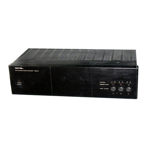
Rotel
Rotel The Power Amp RB-5000 User manual

Rotel
Rotel RB-1000 User manual

Rotel
Rotel RA-2020 User manual

Rotel
Rotel RA-870BX User manual

Rotel
Rotel RB-1092/v02 User manual

Rotel
Rotel RA-700 User manual

Rotel
Rotel RMB-1066 User manual