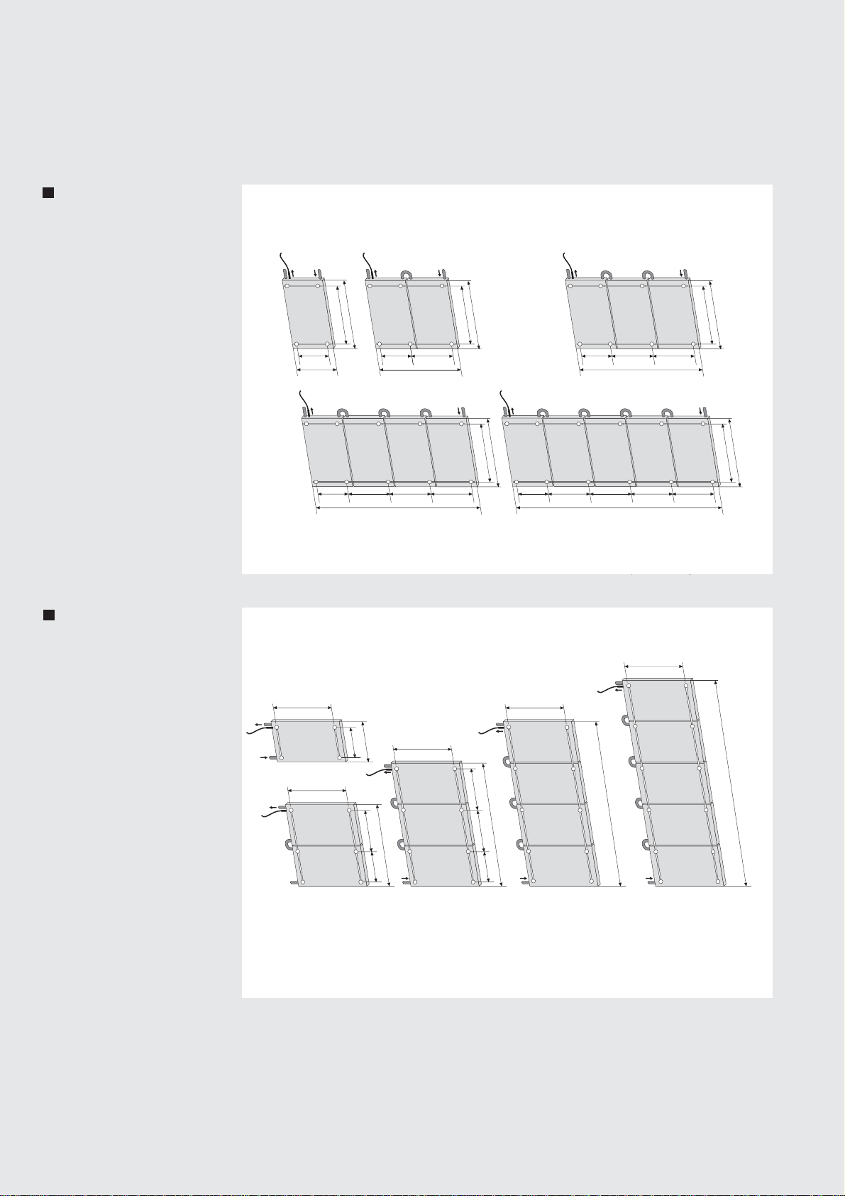
The on-roof attachment set is capable for
installation of Roth flat collectors Heliostar®
on roofs with a slope greater than 22°. One
attachment anchor universal can be used for
roofs with covering made of pantiles/ roofing
tiles and similar roofing stones as well as plain
tiles and fibre-cement corrugated plates.
Installations on roofs made of natural slates
should be carried out by companies employ-
ing professional tilers only.
Please read the installation instructions
before starting the installation carefully
and follow the indicated safety informa-
tion. The valid industrial safety instructions
and regulations of technology especially with
regard to working on the roof have to be
observed (see page 12). In case of higher
loads of snow starting from zone 4 and in
places above 600 m NN, please contact our
technical department to discuss statics of the
installation.
Please note: You may need additional mater-
ial such as ventilation roofing tiles for the roof
lead-through of the collector field connections
(available in special tiler stores and construc-
tion material wholesalers), possibly adjustment
lumbers for padding the rafter anchor, sheet
metal for sealing the rafter anchor when
using plain tiles. To carry the collector on the
roof additional equipment could be required.
Important: When storing the collectors
before installation, make sure the collectors
do not stand outside, lay on the glass and/or
are stocked uncovered, to avoid humidity
entering into the collector through the wholes
in the collector frame. Before installing the
collector connections, they must be annealed.
Therefore, always push strongly against the
1/2” thread connection when tightening.
Non-compliance can result in damage of the
collector.
The metal pipelines of the solar circuit must
be connected through a green/yellow conduc-
tor of min. 16 mm2Cu (H07 V respectively R)
with the main potential adjustment rail. If a
lightning protection installation is available,
the collectors can be linked to it. Earthing can
also be done by a depth earth electrode. The
grounding cable must be placed outside on
the house. In addition the earth electrode
must be connected with the main potential
adjustment rail with a cable of the same
diameter.
Installation requirements
Safety information
Generel requirements
Potential adjustment
and lightning
protection
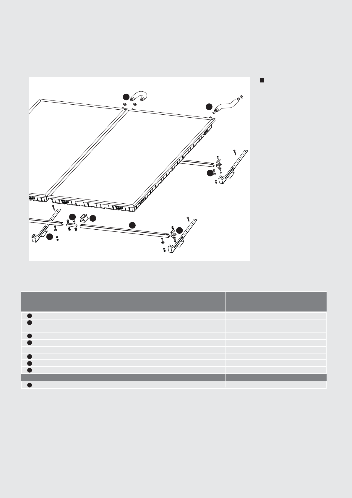
2
• Spanner 13/17/19/20/22
• Boring machine,
• Cross slot PZ 3
• Angle grinder with stone shim
• Hammer
• String (approx. 10 m), measuring tape, rope
• Pencil
Overview of tools
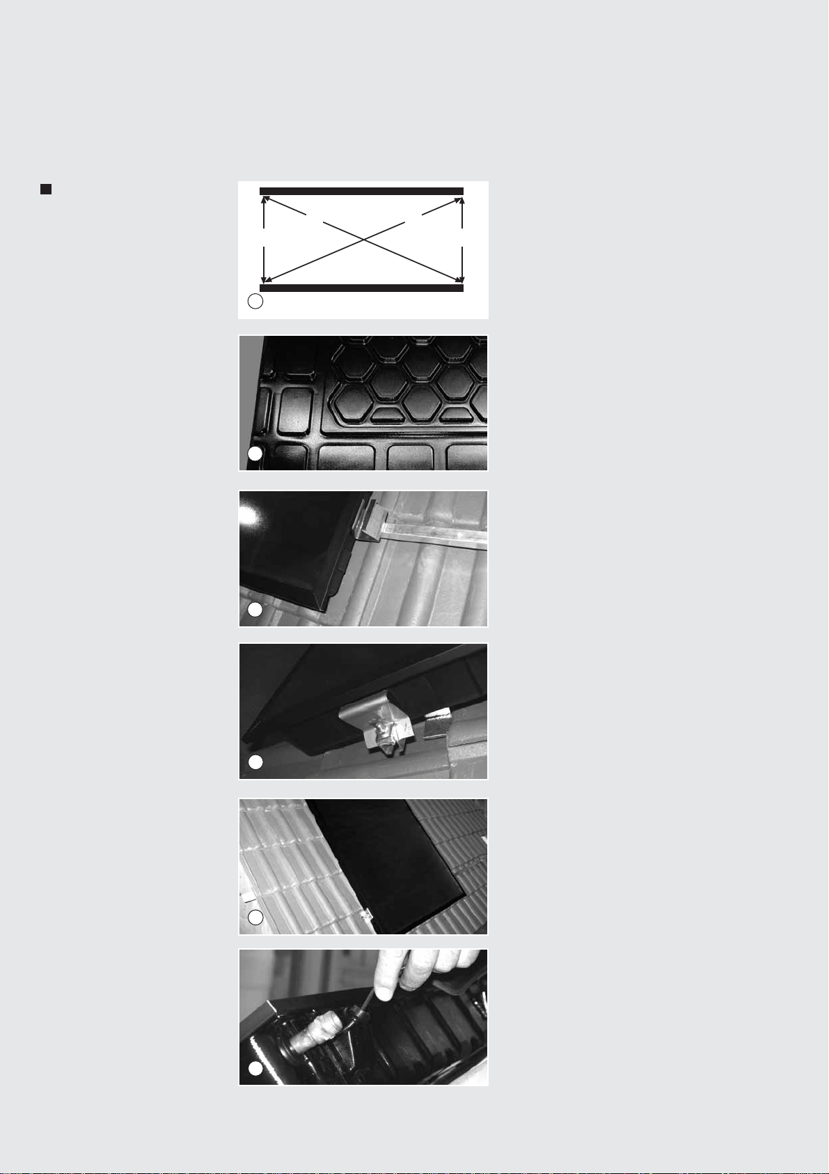
The sensor must be installed in the last flood-
ed collector on the supply side (hot outlet).
For this purpose, the rubber sleeve must be
removed, the sensor must be threaded and
the rock wool inside of the collector should be
pushed aside. Afterwards place some heat
conducting paste on top of the sensor and
insert it as far as possible into the immersion
sleeve. In the end push the rubber sleeve back
into its position until the countering lip inter-
locks with the collector frame. To extend the
cable of the sensor up to 50 m it is sufficient
to choose a cable diameter of 2 x 0,75 mm,
for more than 50 m a diameter of 2 x 1,5 mm
must be used. To protect the connected regu-
lation units against overvoltage the collector
sensor is to be extended appropriately, directly
behind the collector, through an overvoltage
protection case (optional).
Installation of sensor