ALUMERO AS 2.1 User manual

TILED ROOFS
AS 2.1
EN SOLAR INSTALLATION INSTRUCTIONS
1

Before installation, please read the safety instructions at the end of this
installation manual very carefully – and make sure you are using the latest
edition of these instructions.
Layout and planning of this installation system should be conducted using the
ALUMERO Solar.Pro.Tool software. Please ensure you have all the requisite
materials, positioning and layouts for each individual component according
to the project report provided with Solar.Pro.Tool, and/or by your ALUMERO
sales partner. The data have all been calculated within statutory static toleran-
ce levels and are of great importance to the safe and smooth operation of the
system.
Prior to commencement, technicians responsible for installing the photovoltaic
system must ensure the existing roof construction is capable of bearing the
additional loads and forces. We suggest contacting a local statics specialist.
This installation instruction manual explains installation procedures for ALU-
MERO tiled roof components, attachment to the substructure for the roof, and
assembly of the modules.
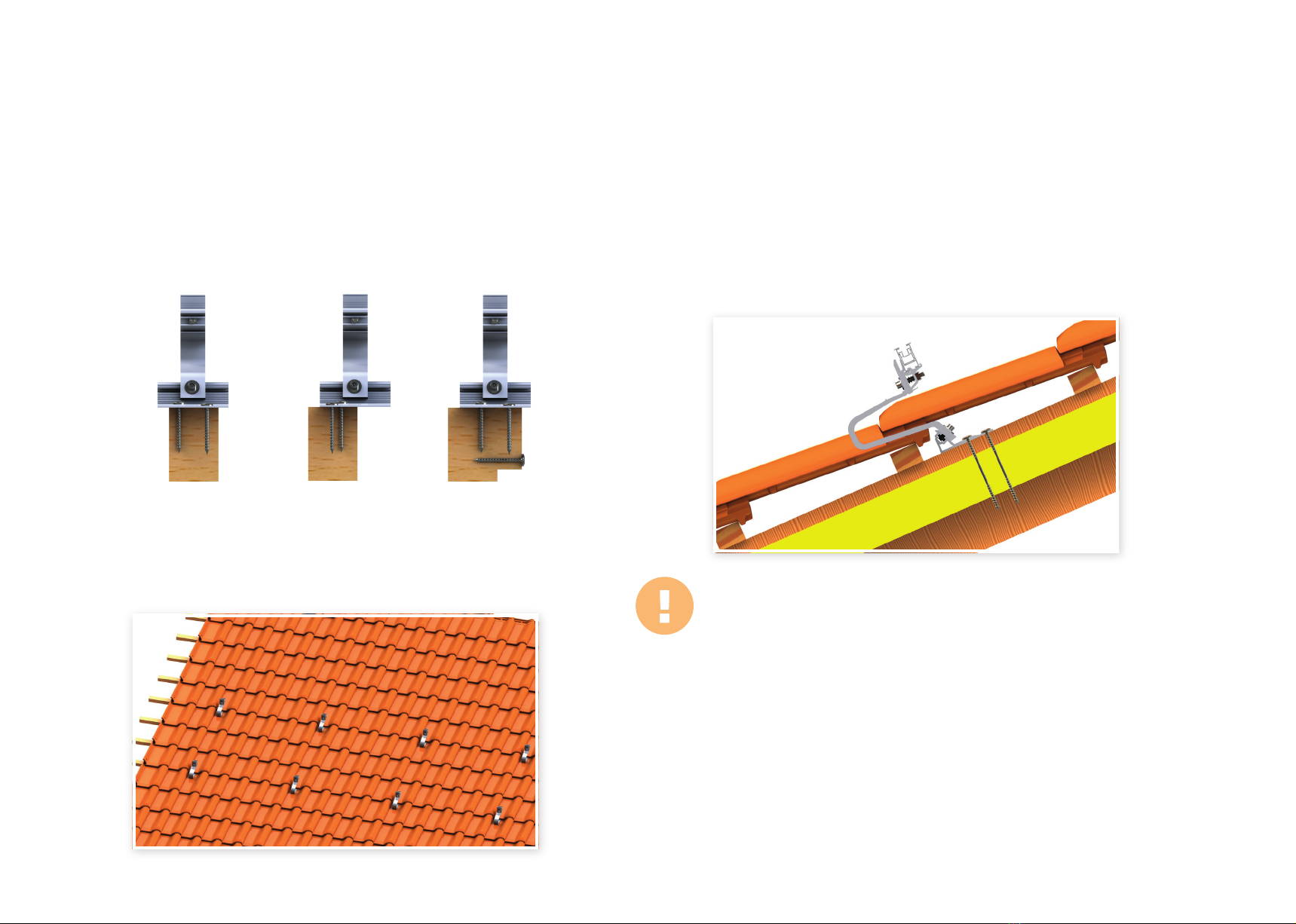
Modules are usually mounted vertically to tiled roofs with the truss profiles pa-
rallel to the roof ridge. Two truss profiles per module row are used as standard.
The ALUMERO tiled roof system is intended solely to carry PV modules. Any
other applications of the system shall be considered examples of misuse.
The use of extra-tilt fixtures is not recommended for tiled roofs.
Mounting must only be conducted by trained personnel. Roofing tasks in parti-
cular should only be carried out by professional roof contractors.
If you have any other questions, please take advantage of our comprehensi-
ve professional advisory service provided by ALUMERO’s expert construction
engineers.
LIST OF CONTENTS
General information................................................................................................. P 3
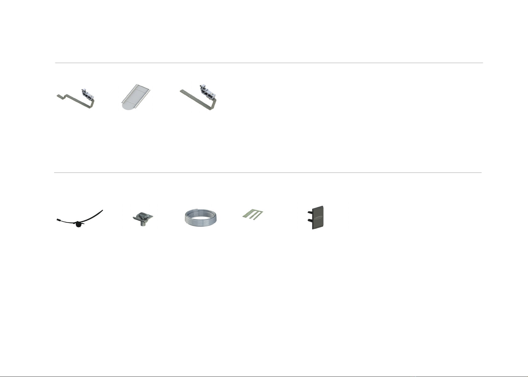
Components........................................................................................................... P 4-5
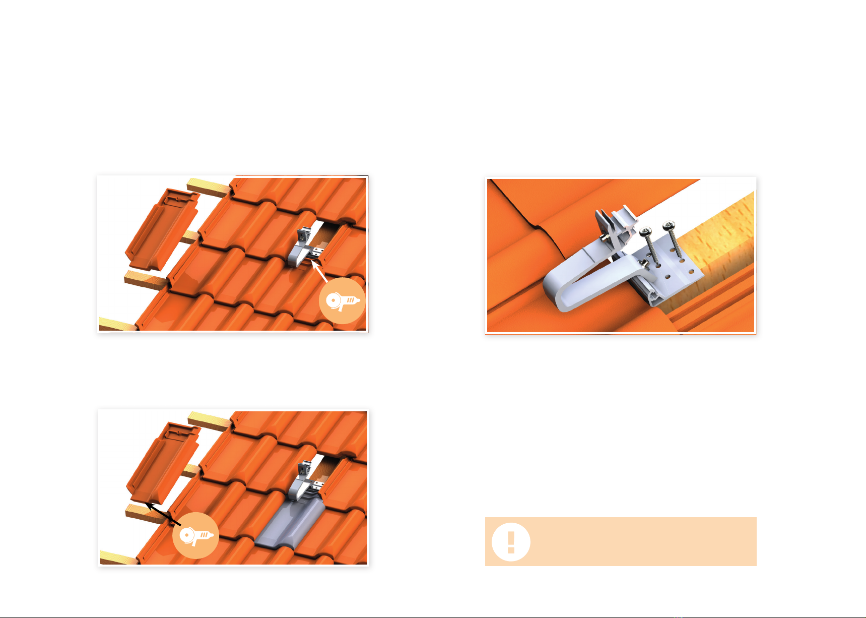
How to attach roof hooks.................................................................................... P 6-9
How to attach beaver tail tile roof hooks........................................................... P 10
How to attach slate tile roof hooks...................................................................... P 11
How to mount truss profiles in a single direction...................................... P 12-13
How to mount truss profiles in a lattice arrangement............................... P 14-16
How to mount modules.......................................................................................... P 17
How to attach AL13 X roof hooks.................................................................. P 18-20
How to mount modules.......................................................................................... P 21
How to attach module cables | Equipotential bonding | Earthing........... P 22-23
Key points........................................................................................................... P 24-28
2

GENERAL INFORMATION
Use: Tiled roofs, beaver tail tiled roofs, slate tile roofs
Roof gradients: 10° - 65°
Means of attachment: Plate head screws
Module arrangement: Vertical / horizontal
Max. module field size: 12m (length)
Screw mounting: MA (A2-70) M10 (A2-70)
Torque: 15 Nm 30 Nm
TOOLS REQUIRED
Torque wrench Measuring tape
Chalk line tool Spirit level
Battery-powered drill
with the following bits:
Hex bit SW 6
Hex key SW6
3

Roof hooks AL13/ALS13
Product number:
80241x
Click end clamp
without a pin
Product number:
802304C
Rapid-mount 40 x 10
roof hook
Product number:
802406
Click end clamp
with a pin
Product number:
802304CP
COMPONENTS
STANDARD
Click middle clamp
with a pin
Product number:
802301C P1 30-45
Click middle clamp
without a pin
Product number:
802301C 30-45
Roof hooks AL13 X
Product number:
802414
Plate head screw
Product number:
8006x
Cross-connector 2.1
Product number:
802200
Profile connector
Product number:
80215x
Truss profile
Product number:
80210x
Preassembled
closing clamp
Product number:
802304-xxV
Preassembled closing
clamp with a pin
Product number:
802304-xxV P1
4

COMPONENTS
ACCESSORIES
Cable tie with a clip
Product number:
802604
Wire clamp
Product number:
802603
Aluminium wire
Product number:
802602
OPTIONAL
Beaver tail sheet
metal tile
Product number:
800666
Rapid-mount slate
tile roof hook
Product number:
802423
Rapid-mount be-
aver tail roof hook
Product number:
802425
Underlay plate
Product number:
80260x
End cap
Product number:
802601
5

MOUNTING WITH ROOF HOOKS
VERTICAL MODULE ARRANGEMENT – SINGLE DIRECTION
6

12MOUNTING THE ROOF HOOKS
Modulklemmbereich
MOUNTING ROOF HOOKS
MEASURE AND MARK POSITIONS
Measure, position and mark the locations for the roof hooks on the roof
according to the Solar.Pro.Tool project report.
Remove the marked roof tile above the rafter.
Position the roof hook so that it protrudes over the trough of the tile below.
The curve of the hook must not touch the tile below. Ensure a gap of at least 3-5mm.
Horizontally there must also be a gap of 3-5mm to the next tile.
Ensure you use the module clamping area provided in the installation
instructions for the module in use.
3-5 mm
3-5 mm3-5 mm
7

MOUNTING THE ROOF HOOKS
Please note:
- The AL13 roof hook can be adjusted in 3 directions to ensure the
required minimum gaps can be adhered to easily. Tighten the fixing
screws to a torque of 15Nm.
- Holes of approx. 0.7 x screw diameter must be pre-drilled in the
wooden substructure..
- Ensure you only cut away part of the lip of the tile and do not cut into
the tile.
- When mounting the sheet metal tile, make sure you use the
manufacturer’s installation instructions.
If necessary, remove a section of the lip of the next tile down using an
angle grinder (diamond blade).
Optionally, the tile below the roof hook can be replaced with a sheet metal
tile. Remove the lip of the tile above with an angle grinder (diamond blade).
Use a string to find the right position for the hook along the horizontal
plane and attach it with two 2 plate head screws driven into the rafter.
Make sure there is a screw in every row of holes.
Please note: Once mounted, roof hooks must not
be used as footholds!
8

POP
MOUNTING THE ROOF HOOKS
Please note:
- The gap between the edge of the plate head screw and the end of the
rafter must be at least 24mm.
- The plate head screw must be inserted to a depth of at least 60mm.
- Ideally recommended for roofs with rafters at least 80mm across, and
at least 60mm.
- It is necessary to pre-drill holes into the wooden substructure when
using wood screws.
- We recommend that roofing tasks should only be carried out by pro-
fessional roof contractors.
Ensure the ground plate of the hook is fully connected to the rafter. Uneven
areas can be compensated for with a variety of extra underlay plates.
Use additional rafters or purlins to ensure the ground plate of the roof
hook is in full contact.
Replace the previously-removed roof tile correctly. If required, remove
part of the lip of the tile an angle grinder. Make sure the roof remains
Where there is insulation between the rafters and the tiles, it is necessary
to use 2 ‘wood screws with fixing threads’ to attach the hooks to the raf-
ters. The wood screws must be anchored at least 60mm into the rafters.
The wood screws with a fixing thread must be provided at the site.
9

12MOUNTING BEAVER TAIL ROOF HOOKS
Modules must only be clamped in the sections prescribed for attach-
ment. These can be found by consulting the manufacturer’s respective
module data sheet.
Module clamping area
Symbolbild
MOUNTING BEAVER TAIL ROOF HOOKS
MEASURE AND MARK POSITIONS
Measure and mark the positions of the roof hooks on the roof using the
Solar.Pro.Tool project report and remove the roof tiles above the rafter.
The tile below the roof hook should be replaced with a sheet metal tile.
Attach the hook with 2 plate head screws driven into the rafter.
Replace the previously-removed roof tile correctly. Make sure the roof re-
mains entirely watertight.
Please note:
- The gap between the edge of the plate head screw and the end of the
rafter must be at least 24mm.
- The plate head screw must be inserted to a depth of at least 60mm.
- Ideally recommended for roofs with rafters at least 80mm across,
and at least 60mm
- It is necessary to pre-drill holes into the wooden substructure when
using wood screws.
- We recommend that roofing tasks should only be carried out by pro-
fessional roof contractors.
10

12MOUNTING SLATE TILE ROOF HOOKS
Modules must only be clamped in the sections prescribed for attach-
ment. These can be found by consulting the manufacturer’s respective
module data sheet.
Module clamping area
Symbolbild
MOUNTING SLATE TILE ROOF HOOKS
MEASURE AND MARK POSITIONS
Measure and mark the positions of the roof hooks on the roof using the
Solar.Pro.Tool project report and remove the roof tiles over each rafter.
If necessary, remove the slates where drilling is required and replace them
with the specially-designed titanium-zinc sheet slates to guarantee the
surrounding slates remain watertight. Attach the hook with 2 plate head
screws driven into the rafter.
Reinstall all roofing correctly and ensure you comply with the directives of
the German Roofers’ Guild.
Please note:
- The gap between the edge of the plate head screw and the end of the
rafter must be at least 24mm.
- The plate head screw must be inserted to a depth of at least 60mm.
- Ideally recommended for roofs with rafters at least 80mm across, and
at least 60mm.
- It is necessary to pre-drill holes into the wooden substructure when
using wood screws.
- We recommend that roofing tasks should only be carried out by pro-
fessional roof contractors
11

1
Max. 30cm
MOUNT TRUSS PROFILE
2
h
CONNECT THE TRUSS PROFILES
Necessary when the width of the module field is greater than the length of
the truss profile.
Push the profile connector halfway into the first truss profile, then connect
the second truss profile to the profile connector.
MOUNTING THE TRUSS PROFILE – SINGLE DIRECTION
Profile connector
Fasteners
Fasteners
Fasteners
Fasteners Fasteners Fasteners
Profile connector
Please note:
- Every truss profile must be attached in at least two places!
- Truss profile end contact surfaces must not be situated at points of
attachment.
- Truss profile length: max. 12m!
- Ensure an expansion joint of at least 5cm is included at a maximum of
every 12m!
- Extensions of the truss profiles beyond the final point of attachment
must not exceed 30cm!
- Measure the correct positions for the profile connectors according
totheSolar.Pro.Toolprojectreportandoptionallyscrewdownthepro
file connector.
Final fastener
Mount the truss profile onto the roof hooks, parallel to the ridge of the roof,
with the correct side up, and tighten to a torque of 15 Nm.
Top
Bottom
12

3ALTERNATIVES FOR ATTACHING TRUSS
PROFILES TO ROOF HOOKS
Attachment with the rapid-mount adapter
Attachment with the T-head anchor bolt
and hex nut
Please note: Ensure truss profiles are mounted straight and
without tension. Tightening torque for fixing screws:
M8 15 Nm / M10 30 Nm.
h
FITTING THE END CAPS
Press the end caps into the open ends of the profiles.
Attachment with the rapid-mount adapter
– height-adjustable
13

MOUNTING TRUSS PROFILES IN A LATTICE ARRANGEMENT
HORIZONTAL MODULE ARRANGEMENT
14

1
2MOUNTING THE CROSS-CONNECTOR
MOUNTING TRUSS PROFILES IN A LATTICE ARRANGEMENT
HORIZONTAL MODULE ARRANGEMENT
MOUNTING THE ‘BASIS RAIL’ TRUSS PROFILE
4
h
CONNECT THE TRUSS PROFILES
Necessary when the width of the module field is greater than the length of
the truss profile.
Push the profile connector halfway into the first truss profile, then connect
the second truss profile to the profile connector.
MOUNTING TRUSS PROFILES IN A LATTICE ARRANGEMENT
Mount the ‘Basis Rail’ truss profile horizontally, parallel to the ridge of the
roof with the correct side up, and tighten to a torque of 15Nm.
Rotate the cross-connector into the ‘basic rail’ and tighten to a torque of
15Nm.
Please note: If the ‘Basis Rail’ profiles are mounted vertically, parallel
to the side ends of the roof, the truss profile fixing screw on the cross-
connector should always be pointing in the direction of the roof ridge.
Mount the ‘Module Rail’ truss profile vertically on the cross-connector,
parallel to the side edges of the roof with the correct side up, and tighten
to a torque of 15Nm.
3MOUNTING THE ‘MODULE RAIL’
TRUSS PROFILE
Top
Bottom
15

Max. 30cm
Profile connector
Fasteners
Fasteners
Fasteners
Fasteners Fasteners Fasteners
Profile connector
Please note:
- Every truss profile must be attached in at least two places!
- Truss profile end contact surfaces must not be situated at points of attachment.
- Truss profile length: max. 12m!
- Ensure an expansion joint of at least 5cm is included at a maximum of every 12m!
- Extensions of the truss profiles beyond the final point of attachment must not ex-
ceed 30cm! These protrusions should be the same length at either end.
- Measure the correct positions for the profile connectors according to the Solar.Pro.
Tool project report and optionally screw down the profile connector.
Final fastener
5
h
FITTING THE END CAPS
Press the end caps into the open ends of the profiles.
MOUNTING THE TRUSS PROFILES IN A LATTICE PATTERN
16

12
MOUNTING THE END CLAMPS
Begin with the bottom row of the module. Lift the first module onto the truss profiles
and position correctly.
Click in the end clamp by slightly tilting, and slide along to the module frame.
Tighten hex screw to a torque of 15 Nm.
Please note: If using end clamps with threaded plates, please
ensure the plate is positioned at 90° to the profile channel.
MOUNTING MODULES
Please note: The end clamps must be
attached at least 20mm from the end of
each mounting profile.
P
As described, each final module on a module row must be mounted with end clamps.
The same applies to the remaining rows of modules.
Please note:
- Ensure there is a gap of at least 20mm between the clamp and the end of the
truss profile
- Middle clamps must not be mounted right at the end of the profiles!
- Modules must only be clamped in the sections prescribed for attachment! These
can be found by consulting the manufacturer’s respective module data sheet.
- Horizontal and vertical gaps between the modules must be around 20mm!
P
123
min. 20 mm
MOUNT THE MIDDLE CLAMP
Click the middle clamp onto the frame of the previous module at a slight angle. Move
the module along until the modules are sitting pressed up to each other!
Tighten hex screw to a torque of 15Nm.
17

MOUNTING WITH AL13 X ROOF HOOKS
VERTICAL MODULE ARRANGEMENT, LATTICE
18

12MOUNTING AL13 X ROOF HOOKS AND TRUSS PROFILES
Modules must only be clamped in the sections prescribed for attach-
ment. These can be found by consulting the manufacturer’s respective
module data sheet. 3MOUNTING THE CROSS-CONNECTOR
Rotate the cross-connector into the ‘basic rail’ and tighten to a torque of
15Nm.
Please note: If the ‘Basis Rail’ profiles are mounted vertically, parallel
to the side ends of the roof, the truss profile fixing screw on the cross-
connector should always be pointing in the direction of the roof ridge.
Module clamping area
MOUNTING AL13 X ROOF HOOKS
MEASURE AND MARK POSITIONS
Measure and mark the positions of the roof hooks on the roof using the
Solar.Pro.Tool project report and remove the roof tiles over each rafter.
The mounting of the AL13 X is conducted as described on pages 7, 8
and 9. Mount the ‘Basis Rail’ truss profile vertically onto the roof hooks,
parallel to the side ends of the roof and with the correct side up, and tighten
the fixing screws to a torque of 15Nm.
19

4
We recommend mounting the modules vertically on a lattice framework.
Info: When using AL13 X roof hooks there is also the option of
mounting the modules horizontally on single-direction rail rows.
Modules must only be clamped in the sections prescribed for
attachment. These can be found by consulting the respective
module’s installation instructions.
Max. 30cm
Profile connector
Fasteners
Fasteners
Fasteners
Fasteners Fasteners Fasteners
Profile connector
Please note:
- Every truss profile must be attached in at least two places!
- Truss profile end contact surfaces must not be situated at points of attachment.
- Truss profile length: max. 12m!
- Ensure an expansion joint of at least 5cm is included at a maximum of every 12m!
- Extensions of the truss profiles beyond the final point of attachment must not ex-
ceed 30cm! These protrusions should be the same length at either end.
Final fastener
MOUNTING AL13 X ROOF HOOKS
MOUNTING THE ‘MODULE RAIL’ TRUSS PROFILE
Mount the ‘Module Rail’ truss profile horizontally on the cross-connec-
tor, parallel to the roof ridge with the correct side up, and tighten to a
torque of 15Nm.
20
Table of contents
Popular Solar Panel manuals by other brands

COMPANION
COMPANION COMPBI023 owner's manual

Trina Solar
Trina Solar VERTEX Series user manual

Cisco
Cisco Firepower 4110 Hardware installation guide

XtremepowerUS
XtremepowerUS 90100 Owner's manual and safety instructions

Ariston
Ariston SOLARcomfort installation instructions

Sunman
Sunman eArc installation manual

XPOtool
XPOtool 61993 Operation manual

BorMann
BorMann BLF2000 installation instructions

AXITEC
AXITEC AXIblackpremium installation manual

Nature Power
Nature Power 2106 user manual

oventrop
oventrop OKF-CK 22 Installation and operating instructions

Vaillant
Vaillant auroTHERM exclusive VTK SERIES installation manual