Carefully read the Warranty section1, detailing coverage and limitations of this warranty.
Warranty is provided for customers who operate and maintain their equipment as
described in this manual. Warranty registration is accomplished by the dealer by
completing and forwarding the Warranty Registration form to the Company, along with
a copy of the dealer’s invoice. It is in your best interest to insure that this has been
done.
Warranty does not cover the following:
1. Cleaning, transporting, mailing and service call charges.
2. Normal wear items such as blades, bearings, wheels, drivelines, shear pins, slip
clutches, etc.
3. Depreciation or damage caused by normal wear, accidents, improper maintenance,
improper protection or improper use.
4. The use of non-original spare parts and accessories.
Your Authorised Company Dealer has genuine parts in stock. Only these approved
replacement parts should be used.
This limited warranty covers defective material and workmanship. The cost of normal
maintenance or repairs for accidents or improper use and related labour will be borne by
the owner.
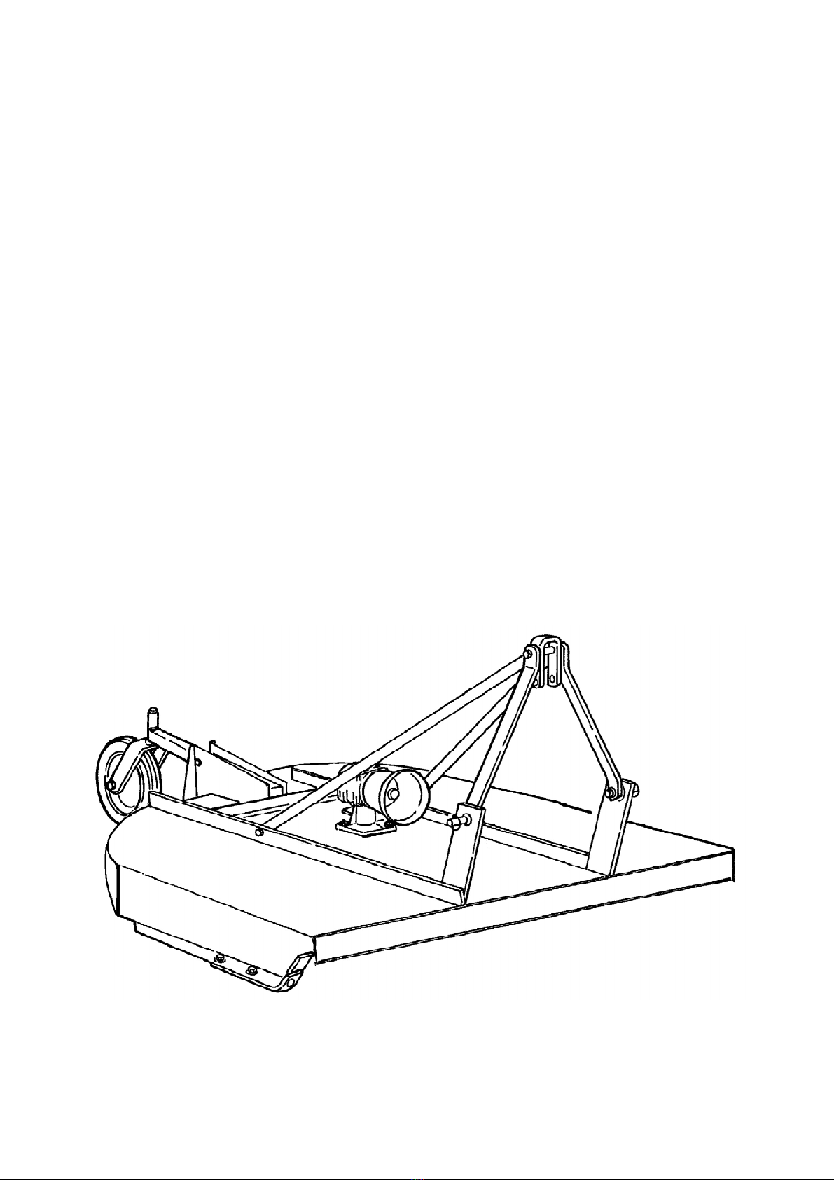
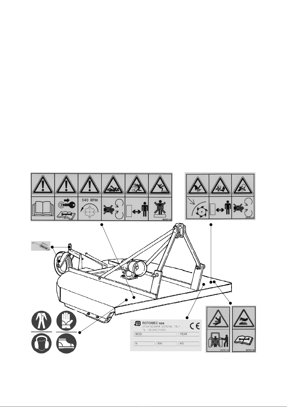
1.03 - Assembly Instructions
For transportation purposes the three point hitch of the rotary cutter is shipped
unassembled.
CAUTION: Stand clear of bands when cutting as they could be under sufficient
tension to cause them to fly loose. Take care in removing bands and wire. They
often have extremely sharp edges and cut very easily.
To assemble proceed as follows:
1. Vertical supports come installed, but are lowered on the frame. Loosen bolts to raise
them and ensure they are installed to the inside of the front support plates welded
on the front of the cutter frame.
2. Install the horizontal supports to the inside of the rear cutter frame using the bolts
M14x40 and the stover nuts M14 provided. Bolt loosely at first.
3. Disassemble top hitch plate in order to position horizontal supports. Reassemble as
follows: Bolt 5/8”x6.5”, vertical support, horizontal support, top hitch plate, spacer,
top hitch plate, horizontal support, vertical support, stover nut 5/8”. Be sure the top
hitch plate swings freely.
4. Install driveline and ensure it has at least 5 cm. (2”) from bottoming out in its shortest
working position and has the minimum 15 cm. (6”) overlap in its longest working
position. Refer to Section 4.052of this manual, if it is determined that the driveline is
GENERAL INFORMATION 6olqljb`
TORNADO RRB OPERATOR’SMANUAL
2See Section 4.05 - Driveline, for instructions on how to determine correct driveline length and
1See Chapter 8 - Warranty.