Rover RS3100 User manual

769-25689 / 00 07/20
RS3100
4-Stroke Trimmer
Operator’s Manual
IMPORTANT: Read this manual thoroughly before using this product. Follow all instructions.
SAVE THESE INSTRUCTIONS

2
TABLE OF CONTENTS
Service . . . . . . . . . . . . . . . . . . . . . . . . . . . . . . . . . . . . . . . . . . . . . . . . . . . . . . . . . . . . . . . . . . . . . . . . . . . . . . . . . . . . . . . . . . 2
Safety . . . . . . . . . . . . . . . . . . . . . . . . . . . . . . . . . . . . . . . . . . . . . . . . . . . . . . . . . . . . . . . . . . . . . . . . . . . . . . . . . . . . . . . . . . . 3
Know Your Unit . . . . . . . . . . . . . . . . . . . . . . . . . . . . . . . . . . . . . . . . . . . . . . . . . . . . . . . . . . . . . . . . . . . . . . . . . . . . . . . . . 10
Specications . . . . . . . . . . . . . . . . . . . . . . . . . . . . . . . . . . . . . . . . . . . . . . . . . . . . . . . . . . . . . . . . . . . . . . . . . . . . . . . . . . 11
Assembly. . . . . . . . . . . . . . . . . . . . . . . . . . . . . . . . . . . . . . . . . . . . . . . . . . . . . . . . . . . . . . . . . . . . . . . . . . . . . . . . . . . . . . . 11
Oil and Fuel . . . . . . . . . . . . . . . . . . . . . . . . . . . . . . . . . . . . . . . . . . . . . . . . . . . . . . . . . . . . . . . . . . . . . . . . . . . . . . . . . . . . 16
Starting and Stopping . . . . . . . . . . . . . . . . . . . . . . . . . . . . . . . . . . . . . . . . . . . . . . . . . . . . . . . . . . . . . . . . . . . . . . . . . . 18
Operation . . . . . . . . . . . . . . . . . . . . . . . . . . . . . . . . . . . . . . . . . . . . . . . . . . . . . . . . . . . . . . . . . . . . . . . . . . . . . . . . . . . . . . 20
Maintenance . . . . . . . . . . . . . . . . . . . . . . . . . . . . . . . . . . . . . . . . . . . . . . . . . . . . . . . . . . . . . . . . . . . . . . . . . . . . . . . . . . . 24
Cleaning and Storage . . . . . . . . . . . . . . . . . . . . . . . . . . . . . . . . . . . . . . . . . . . . . . . . . . . . . . . . . . . . . . . . . . . . . . . . . . . 31
Troubleshooting. . . . . . . . . . . . . . . . . . . . . . . . . . . . . . . . . . . . . . . . . . . . . . . . . . . . . . . . . . . . . . . . . . . . . . . . . . . . . . . . 32
Warranty . . . . . . . . . . . . . . . . . . . . . . . . . . . . . . . . . . . . . . . . . . . . . . . . . . . . . . . . . . . . . . . . . . . . . . . . . . . . . . . . . . . . . . . 34
All information, illustrations, and specications in this manual are based on the latest product information
available at the time of printing. We reserve the right to make changes at any time without notice.
The product may vary slightly from the illustrations contained in this manual.
Copyright© 2020 MTD SOUTHWEST INC, All Rights Reserved.
SERVICE
DO NOT RETURN THIS UNIT TO THE RETAILER. PROOF OF
PURCHASE WILL BE REQUIRED FOR WARRANTY SERVICE.
For assistance regarding the assembly, operation or maintenance of the unit, please call 1300 951 594.
Additional information can be found at www.rover.com.au.
Warranty service is available through an authorised service center. To locate a service center in your
area, please visit our website or call the number listed above. Service on this unit, both within and after
the warranty period, should only be performed by an authorised and approved service center. When
servicing, use only identical replacement parts.
Register your product at www.rover.com.au to have parts, owner manuals, and warranty information
at your ngertips.

3
SAFETY
SPARK ARRESTOR NOTE
NOTE: For users on U.S. Forest Land and in the states of California, Maine, Oregon and
Washington. All U.S. Forest Land and the state of California (Public Resources Codes
4442 and 4443), Oregon and Washington require, by law that certain internal
combustion engines operated on forest brush and/or grass-covered areas be
equipped with a spark arrestor, maintained in eective working order, or the engine
be constructed, equipped and maintained for the prevention of re. Check with
your state or local authorities for regulations pertaining to these requirements.
Failure to follow these requirements could subject you to liability or a ne. This
unit is factory equipped with a spark arrestor. If it requires replacement, contact
your local service dealer to install the appropriate muer assembly.
Read the operator’s manual and follow all warnings and safety instructions. Failure to
do so can result in serious injury to the operator and/or bystanders.
SYMBOL MEANING
WARNING:Signals a SERIOUS hazard.
Failure to obey a safety WARNING symbol CAN result in serious injury to yourself
or to others.
CAUTION:Signals a MODERATE hazard.
Failure to obey a safety CAUTION symbol MAY result in property damage or
injury to yourself or to others.
The purpose of safety symbols is to attract your attention to possible dangers. The safety
symbols, and their explanations, deserve your careful attention and understanding. The
safety warnings do not by themselves eliminate any danger. The instructions or warnings
they give are not substitutes for proper accident prevention measures.
NOTE: Advises you of information or instructions vital to the operation or maintenance of
the equipment.
DANGER:Signals an EXTREME hazard.
Failure to obey a safety DANGER symbol WILL result in serious injury or death to
yourself or to others.

4
• IMPORTANT SAFETY INSTRUCTIONS •
READ ALL INSTRUCTIONS BEFORE OPERATING
• Read the instructions carefully. Be familiar with the controls and proper use of the unit.
Know how to stop the unit and disengage the controls quickly.
• Stay alert. Do not operate this unit when tired, ill or under the inuence of alcohol,
drugs or medication.
• Never allow children to operate the unit. Teens must be trained, accompanied and
supervised by an adult. Never allow adults to operate the unit without proper instruction.
• All guards and safety attachments must be installed properly before operating the unit.
• Inspect the unit before use. Check for damaged parts. Check for fuel leaks. Make sure all
parts operate properly. Make sure all fasteners are in place and secure. Make sure all
moving parts are properly aligned and are not bound. Replace parts that are cracked,
chipped, or damaged in any way. Have all damaged or improperly working parts
repaired or replaced by an authorised service center. Do not operate the unit with loose
or damaged parts.
• Be aware of risk of injury to the head, hands and feet.
• Carefully inspect the area before starting the unit. Remove rocks, broken glass, nails,
wire, string and other objects that may be thrown or become entangled with the unit.
• Clear the area of children, bystanders and pets; keep them outside a 50-foot (15 m)
radius, at a minimum. Even then, they are still at risk from thrown objects. Encourage
bystanders to wear eye protection. If you are approached, stop the unit immediately.
• Squeeze the throttle control and check that it returns automatically to the idle position.
Make all adjustments or repairs before using the unit.
• Do not change the engine governor settings or overspeed the engine.
• This unit is intended for occasional, household use only.
WARNING:When using the unit, all safety instructions must be
followed. Please read these instructions before operating the unit in order to
ensure the safety of the operator and any bystanders. Please keep these
instructions for later use.

5
SAFETY WARNINGS FOR GAS UNITS
• Store fuel only in containers specically designed and approved for the storage of such
materials.
• Always stop the engine and allow it to cool before lling the tank. Never remove the
fuel tank cap or add fuel when the engine is hot. Always loosen the fuel tank cap slowly
to relieve any pressure in the tank before fueling.
• Always add fuel in a clean, well-ventilated outdoor area where there are no sparks or
ames. DO NOT smoke.
• Never operate the unit without the fuel cap securely in place.
• Avoid creating a source of ignition for spilled fuel. Wipe up any spilled fuel from the unit
immediately, before starting the unit. Move the unit at least 30 ft. (9.1 m) from the
fueling source and site before starting the engine. DO NOT smoke.
• Never start or run the unit inside a closed room or building. Breathing exhaust fumes
can kill. Operate this unit only in a well-ventilated outdoor area.
WARNING:Gasoline is highly ammable and its vapors can
explode if ignited. Take the following precautions:
WHILE OPERATING
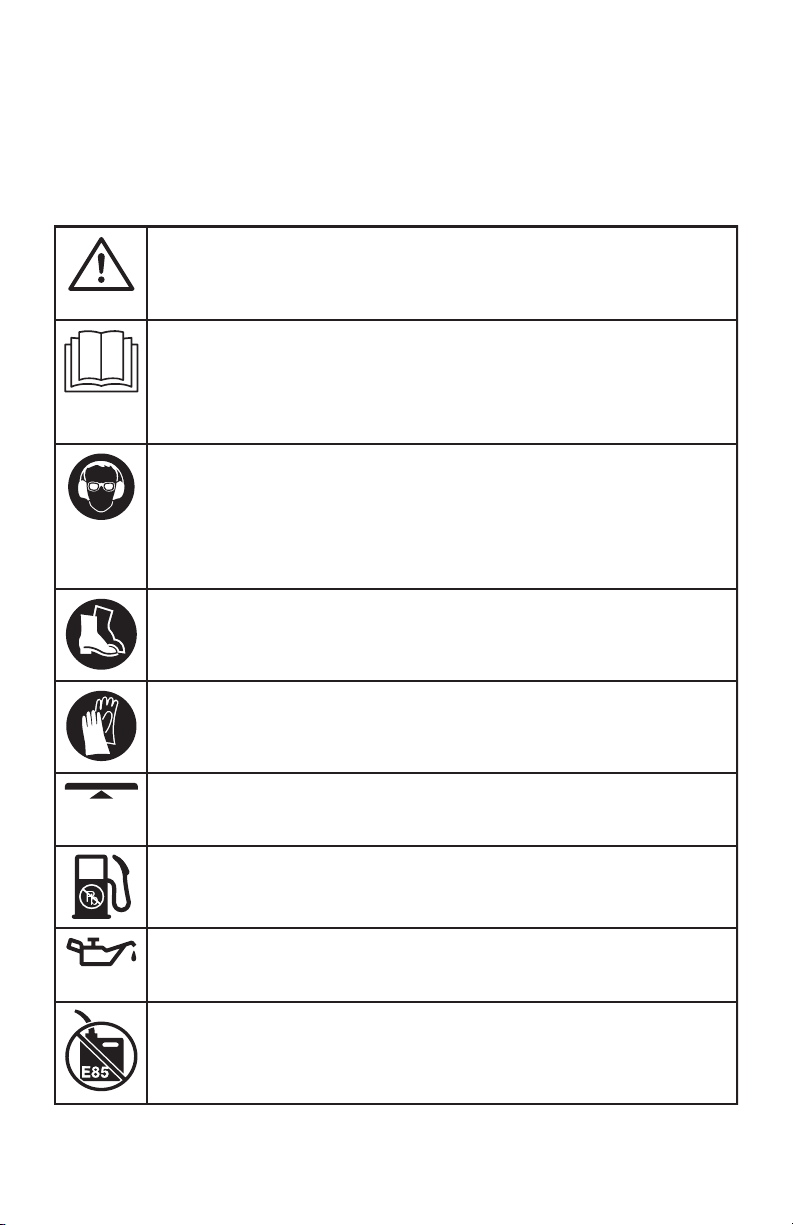
• Wear safety glasses or goggles that meet current ANSI / ISEA Z87.1 standards and are
marked as such. Wear ear/hearing protection when operating this unit. Wear a face
mask or dust mask if the operation is dusty.
• Wear heavy long pants, boots, gloves and a long sleeve shirt. Do not wear loose
clothing, jewelry, short pants, sandals or go barefoot. Secure hair above shoulder level.
• Adjust the handle to provide the best grip, if applicable.
• Use the unit only in daylight or good articial light.
•Avoid accidental starting. Be in the starting position whenever pulling the starter rope. The
operator and unit must be in a stable position while starting. Refer to Starting and Stopping.
• Use the right tool. Only use this tool for its intended purpose. Only use the unit as
described in this manual.
• Always hold the unit with both hands when operating. Keep a rm grip on both
handles or grips.
• Do not overreach. Always keep proper footing and balance. Take extra care when
working on stairs, steep slopes or inclines. To avoid serious injury, do not operate the
unit while on a ladder or a roof.
• Keep hands, face, and feet away from all moving parts. Do not touch or try to stop
moving parts.
• Do not touch the engine, gear housing or muer. These parts get extremely hot from
operation, even after the unit is turned o.
• Do not operate the unit faster than the speed needed to do the job. Do not run the unit
at high speed when not in use.

6
• Do not force the unit. It will do a better, safer job when used at the intended rate.
• Always turn the unit o when operation is delayed or when carrying the unit from one
location to another. Make sure all moving parts come to a complete stop.
• Before setting the unit down, always make sure the engine is o and all moving parts
have stopped.
• If the unit strikes or becomes entangled with a foreign object, stop the unit
immediately. Check for damage. If damaged, do not restart or operate the unit until it is
repaired. Do not operate the unit with loose or damaged parts.
• Turn the engine o and disconnect the spark plug for maintenance or repair.
• Use only original equipment manufacturer (OEM) replacement parts and accessories for
this unit. These are available from your authorised service dealer. Use of any other parts
or accessories could lead to serious injury to the user, or damage to the unit, and void
the warranty.
• Keep the unit clean. Carefully remove vegetation and other debris that could block
moving parts.
• To reduce re hazard, replace a faulty muer and spark arrestor. Keep the engine and
muer free from grass, leaves, excessive grease or carbon build up.
• If the unit starts to vibrate abnormally, stop the unit immediately. Inspect the unit for
the cause of the vibration. Vibration is generally an indicator of trouble.
TRIMMER SAFETY
• Only use the trimming line described in the Specications section of this manual. Never
use metal-reinforced line, wire, chain or rope. These can break o and become
dangerous projectiles.
• Do not replace the cutting head with rigid or metal blades. Doing so could result in
serious injury.
• The cutting head shield must always be in place while operating the unit.
• Do not operate the unit without both trimming lines extended and the proper line
installed. Do not extend the trimming line beyond the length of the shield.
• The cutting head should remain stationary when the engine idles. If it does not, refer to
Adjusting the Idle Speed.
• Make sure the cutting head is not in contact with anything before starting the unit.

7
OTHER SAFETY WARNINGS
• Maintain the unit with care. Follow all maintenance instructions in this manual.
•Do not perform maintenance procedures other than those described in this manual. All
service, other than the maintenance procedures described in this manual, should be
performed by an authorised service dealer.
• Never remove, modify or make inoperative any safety device furnished with the unit.
• Before inspecting, maintaining, cleaning, storing, transporting or replacing any parts on
the unit:
1. Stop the unit. Refer to Starting and Stopping.
2. Make sure all moving parts have stopped.
3. Allow the unit to cool.
4. Disconnect the spark plug wire.
• Secure the unit while transporting.
• Never store the unit with fuel in the tank, inside a building where fumes may reach an
open ame (pilot lights, etc.) or sparks (switches, electrical motors, etc.).
• Store the unit in a dry place, secured or at a height to prevent unauthorised use or
damage. Keep the unit out of the reach of children.
• Never douse or squirt the unit with water or any other liquid. Keep handles dry and
clean (free from debris, oil and grease). Clean the unit after each use. Refer to Cleaning
and Storage. Do not use solvents or strong detergents.
• Keep these instructions. Refer to them often and use them to instruct other users. If you
loan this unit to others, also loan them these instructions.
SAVE THESE INSTRUCTIONS

8
SAFETY & INTERNATIONAL SYMBOLS
This operator's manual describes safety and international symbols and pictographs that
may appear on this product. Read the operator's manual for complete safety, assembly,
operating and maintenance and repair information.
SYMBOL MEANING
SAFETY ALERT SYMBOL
Indicates danger, warning or caution. May be used in conjunction with other
symbols or pictographs.
READ OPERATOR'S MANUAL
WARNING:Read the operator’s manual(s) and follow all
warnings and safety instructions. Failure to do so can result in serious injury
to the operator and/or bystanders.
WEAR EYE AND HEARING PROTECTION
WARNING:Thrown objects and loud noise can cause severe
eye injury and hearing loss. Wear eye protection meeting current ANSI / ISEA
Z87.1 standards and ear protection when operating this unit. Use a full face
shield when needed.
WEAR FOOT PROTECTION
Always wear heavy-duty, non-slip footwear when operating this unit.
WEAR HAND PROTECTION
Always wear heavy-duty, non-slip gloves when handling this unit.
HANDLE POSITION
Make sure the handle is positioned beyond the end of the safety label.
UNLEADED FUEL
Always use clean, fresh unleaded fuel.
OIL
Refer to operator’s manual for the proper type of oil.
DO NOT USE E85 FUEL IN THIS UNIT
CAUTION:It has been proven that fuel containing greater than
10% ethanol will likely damage this engine and void the warranty.

9
ON / OFF STOP CONTROL
ON / START / RUN
ON / OFF STOP CONTROL
OFF or STOP
PRIMER BULB
Push the primer bulb, fully and slowly, 10 times.
THROWN OBJECTS CAN CAUSE SEVERE INJURY
WARNING:Small objects can be propelled at high speed,
causing injury.
Min. 50 ft
15 m
KEEP BYSTANDERS AWAY
WARNING:Keep all bystanders, especially children and pets, at
least 50 feet (15 m) from the operating area.
HOT SURFACE
WARNING:Do not touch a hot muer or cylinder. You may get
burned. These parts get extremely hot from operation. When turned o, they
remain hot for a short time.
SHARP BLADE
WARNING:There is a sharp blade on the cutting head shield.
To prevent serious injury, do not touch the line cutting blade.
DO NOT REPLACE CUTTING HEADS WITH BLADES*
WARNING:When using a trimmer, to prevent serious injury, do
not replace the cutting head with rigid or metal blades.
*This warning does not apply to units equipped with blades, such as edgers and
brush cutters.
SYMBOL MEANING

10
KNOW YOUR UNIT
APPLICATIONS (AS A TRIMMER)*
• Cutting grass and light weeds.
•Edging
• Decorative trimming around trees, fences, etc.
*Other optional attachments may be used with this unit.
ASSEMBLY TOOLS REQUIRED
• Flat-head screwdriver
Cutting Head
Shield
Cutting Head
Line Cutting Blade
Coupler
Upper Shaft Housing
Lower Shaft Housing
Handle
On/O Switch
Spark Plug
Muer
Fuel Cap
Starter Rope Grip
Shaft Grip
Throttle Control
Air Filter Cover
Primer Bulb
Oil Fill Plug
Throttle Lockout
Hanger Cap
Shoulder Strap Loop

11
SPECIFICATIONS*
* All specications are based on the latest product information available at the time of printing. We
reserve the right to make changes at any time without notice.
ASSEMBLY
Engine Type . . . . . . . . . . . . . . . . . . . . . . . . . . . . . . . . . . . . . . . . . . . . . . . . . . . . . . . . . . . . . . . . . . . . . Air-Cooled, 4-Stroke
Displacement. . . . . . . . . . . . . . . . . . . . . . . . . . . . . . . . . . . . . . . . . . . . . . . . . . . . . . . . . . . . . . . . . . . . . . 30 cc (1.83 cu. in.)
Spark Plug Gap . . . . . . . . . . . . . . . . . . . . . . . . . . . . . . . . . . . . . . . . . . . . . . . . . . . . . . . . . . . . . . . . . . 0.025 in. (0.635 mm)
Spark Plug . . . . . . . . . . . . . . . . . . . . . . . . . . . . . . . . . . . . . . . . . . . . . . . . . . . . . Champion® QDZ4H or Equivalent Plug
Lubrication . . . . . . . . . . . . . . . . . . . . . . . . . . . . . . . . . . . . . . . . . . . . . . . . . . . . . . . . . . . . . . . . . . . . . . . . . . . . . . . . SAE 30 Oil
Crankcase Oil Capacity . . . . . . . . . . . . . . . . . . . . . . . . . . . . . . . . . . . . . . . . . . . . . . . . . . . . . . . . . . . . . 3.04 . oz. (90 ml)
Fuel Tank Capacity . . . . . . . . . . . . . . . . . . . . . . . . . . . . . . . . . . . . . . . . . . . . . . . . . . . . . . . . . . . . . . . . . . 15 . oz. (444 ml)
Approximate Unit Weight (No Fuel). . . . . . . . . . . . . . . . . . . . . . . . . . . . . . . . . . . . . . . . . . . . 14 - 15 lbs. (6.4 - 6.8 kg)
Trimmer Mechanism . . . . . . . . . . . . . . . . . . . . . . . . . . . . . . . . . . . . . . . . . . . . . . . . . . . . . . . . . . . . . . . . . . . . . Bump Head
Trimming Line Diameter . . . . . . . . . . . . . . . . . . . . . . . . . . . . . . . . . . . . . . . . . . . . . . . . . . . . . . . . . . 0.095 in. (2.41 mm)
Cutting Path Diameter . . . . . . . . . . . . . . . . . . . . . . . . . . . . . . . . . . . . . . . . . . . . . . . . . . . . . . . . . . . . . . . . 17 in. (43.2 cm)
INSTALLING THE CUTTING HEAD SHIELD
1. Remove the wing nut and washer from the cutting head shield.
2. Insert the short tab (the one without a hole) on the mount bracket into the slot on the cutting head
shield (Fig. 1).
3. Rotate the cutting head shield until the bolt on the cutting head shield protrudes through the hole
on the mount bracket (Fig. 1).
4. Place the washer onto the bolt (Fig. 2).
5. Screw the wing nut onto the bolt until the cutting head shield is rmly in place (Fig. 2).
WARNING:To prevent serious personal injury, never operate the unit without the
cutting head shield in place.
Fig. 1
Mount Bracket
Cutting Head Shield
Slot
Tab
Bolt
Hole

12
Fig. 2
Washer
Bolt
Wing Nut
INSTALLING AND REMOVING THE ATTACHMENT
The coupler enables the use of various optional attachments.
Installing the Attachment
1. Remove the hanger cap from the attachment. Keep the hanger cap for use when storing the
attachment. If present, remove the gray spacer from the coupler.
2. Set the unit on a at, level surface.
3. Turn the knob counterclockwise to loosen the coupler (Fig. 3).
4. Align the release button with the guide recess (Fig. 5).
5. Push the attachment straight into the coupler (Fig. 4) until the release button snaps rmly into the
primary hole (Fig. 5).
6. Turn the knob clockwise to tighten the coupler (Fig. 3).
WARNING: Before using any attachment, read and understand the manual that came
with the attachment. Follow all safety information contained within.
WARNING:To avoid serious personal injury and damage to the unit, shut the unit o
before removing or installing an attachment.
WARNING: Before operating the unit, make sure the release button is fully snapped
into the primary hole and the knob is securely tightened.
WARNING: Unless specied otherwise, the release button should be snapped into
the primary hole only. Using the wrong hole could lead to personal injury or damage to the
unit.

13
Fig. 3
Knob
Tighten
Loosen
Fig. 4
Coupler Attachment
Fig. 5
Release Button
Guide Recess
Primary Hole
Removing the Attachment
1. Set the unit on a at, level surface.
2. Turn the knob counterclockwise to loosen the coupler (Fig. 3).
3. Press and hold the release button (Fig. 5).
4. Pull the attachment straight out of the coupler (Fig. 4).

14
INSTALLING AND ADJUSTING THE HANDLE
Installing the Handle
1. Push the handle down onto the upper shaft housing (Fig. 6). Make sure the bolt hole faces to the
right (Fig. 6).
2. Insert the bolt into the bolt hole and push it through (Fig. 6). Tighten the bolt with a at-head
screwdriver, but do not tighten the bolt completely.
3. Hold the unit in the operating position (Fig. 14). Move the handle up or down the upper shaft
housing to a comfortable location (Fig. 6). Make sure the handle is positioned beyond the end of
the safety label (Fig. 6).
4. Tighten the bolt with a at-head screwdriver until the handle is secure.
Adjusting the Handle
If the handle requires adjustment:
1. Loosen the bolt with a at-head screwdriver (Fig. 6).
2. Hold the unit in the operating position (Fig. 14). Move the handle up or down the upper shaft
housing to a comfortable location (Fig. 6). Make sure the handle is positioned beyond the end of
the safety label (Fig. 6).
3. Tighten the bolt with a at-head screwdriver until the handle is secure.
Fig. 6
Bolt Hole
Handle
Upper Shaft
Housing
Bolt
Safety Label
ASSEMBLING AND USING THE SHOULDER STRAP
Assembling the Shoulder Strap
1. Push the strap up through the center slot in the buckle (Fig. 7).
2. Bend the strap over and push it down through the lower slot in the buckle (Fig. 7).
Using the Shoulder Strap
1. Put the shoulder strap over the operator’s head and onto the left shoulder.
2. Start the unit. Refer to Starting and Stopping.
3. Snap the clip onto the shoulder strap loop (Fig. 8).
4. Adjust the shoulder strap to t the operator (Fig. 9). Pull the buckle up to loosen the shoulder strap.
Pull the strap down to tighten the shoulder strap.

15
Fig. 7
Strap
Buckle
Clip
Center Slot
Lower Slot
Fig. 8
Clip
Shoulder Strap Loop
Fig. 9
Strap
Buckle

16
OIL AND FUEL
USING THE RIGHT OIL
Use a high-quality SAE 30 weight oil. DO NOT use dirty oil. Failure to use clean oil of the correct type
can cause premature engine wear and failure.
ADDING OIL: INITIAL USE
NOTE: This unit was shipped without oil in the crankcase. Oil must be added before starting the unit.
NOTE: Never add oil to the fuel tank. This unit has a four-stroke engine. DO NOT mix oil with gasoline.
1. Set the unit on a at, level surface.
2. Unscrew the oil ll plug (Fig. 10).
3. Pour 3.04 uid oz. (90 ml) of oil into the oil ll hole (Fig. 10).
NOTE: This unit comes with a 3.04 uid oz. (90 ml) container of oil.
NOTE: DO NOT overll. Refer to Checking the Oil Level.
4. Wipe up any oil that may have spilled.
5. Make sure the O-ring is in place on the oil ll plug (Fig. 10).
6. Reinstall the oil ll plug.
WARNING: DO NOT overll the crankcase.
OVERFILLING THE CRANKCASE MAY CAUSE SERIOUS PERSONAL INJURY.
Fig. 10
Oil Fill Plug
Oil Fill Hole
O-Ring

17
USING THE RIGHT FUEL
The use of old fuel is the most common cause of performance problems. Use only fresh, clean
unleaded gasoline.
NOTE: This unit has a four-stroke engine. DO NOT mix oil with gasoline.
Denition of Blended Fuels
Today's fuels are often a blend of gasoline and oxygenates such as ethanol, methanol or MTBE (ether).
Alcohol-blended fuel absorbs water. As little as 1% water in the fuel can make fuel and oil separate,
forming acids when stored. ALWAYS use fresh fuel (less than 30 days old).
NOTE: Dispose of old fuel according to federal, state and local regulations.
Using Blended Fuels
If using a blended fuel:
• Always use fresh unleaded gasoline
• Use a fuel additive
Using Fuel Additives
Use a fuel additive to inhibit corrosion and minimize gum deposits. Add 0.8 oz. (23 ml) of fuel additive
per gallon of fuel, according to the instructions on the container. NEVER add fuel additives directly to
the unit's fuel tank.
CAUTION: DO NOT USE E85 FUEL IN THIS UNIT.
It has been proven that fuel containing greater than 10% ethanol will likely damage this
engine and void the warranty.
FUELING THE UNIT
1. Position the unit with the fuel cap facing up.
2. Slowly remove the fuel cap.
3. Place the fuel container spout into the fuel tank ll hole and ll the tank.
NOTE: DO NOT overll the tank.
4. Wipe up any fuel that may have spilled.
5. Reinstall the fuel cap.
6. Move the unit at least 30 ft. (9.1 m) from the fuel container and the fueling site before starting the engine.
WARNING: Gasoline is extremely ammable. Ignited vapors may explode. Always
stop the engine and allow it to cool before lling the fuel tank. Do not smoke while lling
the tank. Keep sparks and open ames at a distance from the area.
WARNING: Remove the fuel cap slowly to avoid injury from fuel spray. Never operate
the unit without the fuel cap securely in place.
WARNING: Add fuel in a clean, well-ventilated outdoor area. Wipe up any spilled fuel
immediately. Avoid creating a source of ignition for spilled fuel. Do not start the engine
until fuel vapors dissipate.

18
STARTING AND STOPPING
WARNING: Operate this unit only in a well-ventilated outdoor area. Carbon
monoxide exhaust fumes can be lethal in a conned area.
WARNING: Avoid accidentally starting the unit. To avoid serious injury, the operator
and the unit must be in a stable position when pulling the starter rope (Fig. 13).
STARTING INSTRUCTIONS
NOTE: To prevent the throttle control from being squeezed accidentally, this unit has a throttle
lockout. The throttle control cannot be squeezed unless the throttle lockout is also engaged.
NOTE: There is no need to turn the unit on. The On/O switch is in the On ( I ) position at all times (Fig. 11).
Before Starting the Unit
1. Check the oil level. Refer to Checking the Oil Level.
2. Fill the fuel tank. Refer to Fueling the Unit.
3. Put the shoulder strap over the operator’s head and onto the left shoulder (Fig. 13).
Starting the Unit
1. Slowly press and release the primer bulb 10 times (Fig. 12).
2. Crouch in the starting position (Fig. 13).
3. Press and hold the throttle lockout (Fig. 11). Squeeze and hold the throttle control (Fig. 11).
4. Continue to hold the throttle lockout and throttle control. Pull the starter rope with a controlled
and steady motion until the unit starts (Fig. 13).
IF... the engine does not start after pulling the starter rope 10 times, repeat the starting procedure.
IF... the engine fails to start after 3 attempts, begin the starting procedure with step 2.
IF... the engine stops while the throttle control is squeezed, repeat the starting procedure.
IF THE ENGINE IS HOT... repeat the starting procedure.
After Starting the Unit
1. Snap the shoulder strap clip onto the shoulder strap loop. Adjust the shoulder strap to t the
operator. Refer to Assembling and Using the Shoulder Strap.
STOPPING INSTRUCTIONS
1. Release the throttle control and allow the engine to idle.
2. Press and hold the On/O switch in the O (O) position until the engine comes to a complete stop
(Fig. 11).

19
Fig. 12
Primer Bulb
Fig. 11
Throttle Control
Throttle
Lockout
On/O Switch
(I = On / O = O)
Fig. 13
Starting
Position
Throttle Control
Starter Rope Grip
Shoulder Strap

20
OPERATION
HOLDING THE UNIT
• Stand in the operating position (Fig. 14). Stand up straight. Do not bend over.
• Keep feet apart and rmly planted.
• Hold the shaft grip with the right hand. Keep the right arm slightly bent.
• Hold the handle with the left hand. Keep the left arm straight.
• Hold the unit at waist level.
• Position the cutting head a few inches above the ground.
WARNING: Always wear eye, hearing, hand, foot and body protection to reduce the
risk of injury when operating this unit.
WARNING:To prevent serious personal injury, avoid arm contact with the engine
while operating the unit. The engine may be extremely hot.
Fig. 14
ADJUSTING THE TRIMMING LINE LENGTH
This unit is equipped with a bump head. Trimming line can be released from the cutting head without
stopping the engine.
To release more line, lightly tap the bump knob on the ground (Fig. 15) while operating the unit at high
speed. For best results, tap the bump knob on bare ground or hard soil. Attempting to release line in
tall grass may stall the engine.
NOTE: Do not rest the cutting head on the ground while the unit is running.
Each time the bump knob is tapped, about 1.5 inches (38 mm) of trimming line is released.
NOTE: Always keep the trimming line fully extended. Line release becomes more dicult when the
cutting line gets shorter.
A blade in the cutting head shield will cut the line to the proper length if any excess line is released.
Table of contents
Other Rover Trimmer manuals