degdrive DGI900 User manual

User Manual
DGI900

2
Contents
Preface 1
Chapter 1 Safety Precautions 4
1.1 Unpackage Inspection 4
1.2 Safety Information 4
1.3 General Precautions 8
1.4 Disposal 10
Chapter 2 Models and Specifications 11
2.1 Models 11
2.2 Specifications 12
2.3 Parts of Inverter 15
2.4 Dimensions 16
2.5 Optional Parts 19
Chapter 3 Installation and Wire Connection 23
3.1 Installation 23
3.2 Removing and Mounting Front Cover of Inverter 24
3.3 Wire Connection 24
3.4 Main Circuit Wiring 25
3.5 Basic Wiring Diagram 27
3.6 Control Circuit Terminal Wiring 27
3.7 EMC Installation Instruction 35

3
Chapter 4 Running of Inverter 39
4.1 Running of Inverter 39
4.2 Operation and Using of the Control Panel 42
4.3 Inverter power switch on 49
Chapter 5 Function Code Table 50
Chapter 6 Description of Function Codes 98
6.1 Basic Parameters(Group P0)98
6.2 Start/Stop Control(Group P1)106
6.3 Auxiliary Functions(Group P2)111
6.4 Input Terminals(Group P3)124
6.5 Output Terminals(Group P4)139
6.6 V/F Control Parameter(Group P5)145
6.7 PID Function(Group P6)150
6.8 Operation Panel and Display(Group P7)157
6.9 Motor Parameters(Group P8)160
6.10 Torque Control and Vector Control Parameters (Group P9)163
6.11 Parameter Protection(Group PA)168
6.12 Multi Reference and Simple PLC Function(Group Pb)177
6.13 Communication Parameter (Group PC)180
6.14 Function Code Parameter(Group Pd)180
6.15 Swing Frequency, Fixed Length and Count(Group PE)181
6.16 AI/AO Correction and AI Curve Setting(Group PF)184
6.17 User Defined Function Codes(Group E0)188
6.18 Motor 2 to Motor 4 Parameters(Group E3、E4、E5)189
6.19 Standard Monitoring Parameters(Group b0)189
Chapter 7 Troubleshooting 190
7.1 Fault Alarm and Troubleshooting 190

4
7.2 Fault Record Search 195
7.3 Fault Reset 195
Chapter 8 Preservation and Maintenance 196
8.1 Preservation and Maintenance 196
8.2 Periodic Preservation and Maintenance 196
8.3 Warranty of Inverter 197
Chapter 9 Serial port RS485 communication protocol 199
9.1 Communication overview 199
9.2 Communication protocol specification 199
9.3 RTU protocol 200
5
Chapter 1 Safety Precautions
Unpackage Inspection
Upon unpacking, check:
• Whether the nameplate model and AC drive ratings are consistent with your order. The box
contains the AC drive, certificate of conformity, user manual and warranty card.
• Whether the AC drive is damaged during transportation. If you find any omission or
damage, contact your supplier immediately.
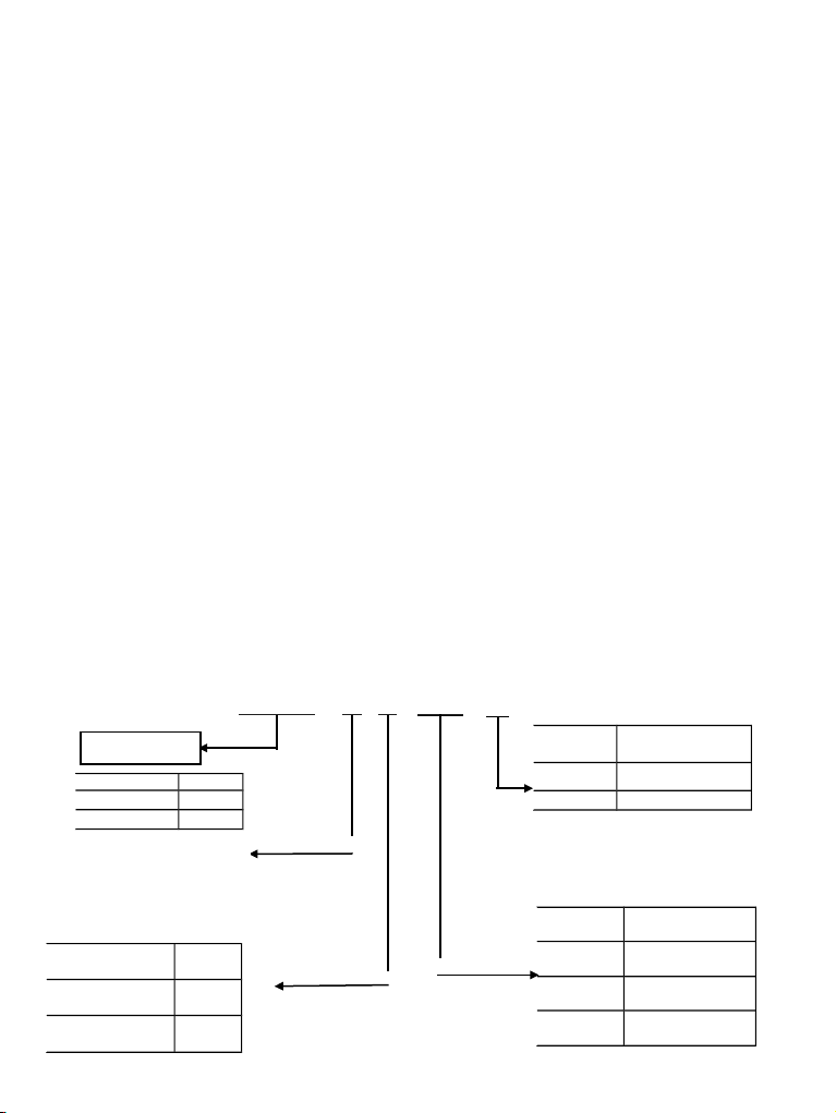
Voltage Code
220V 2
380V 4
Input voltage Code
Single phase S
Three phases T
Code Inverter type
GConstant torque
PPump& Fan
Abbreviation
DGI900 - 4 T 0015 G
Code Power rate
0007 0.75KW
0015 1.5KW
0075 7.5KW
6
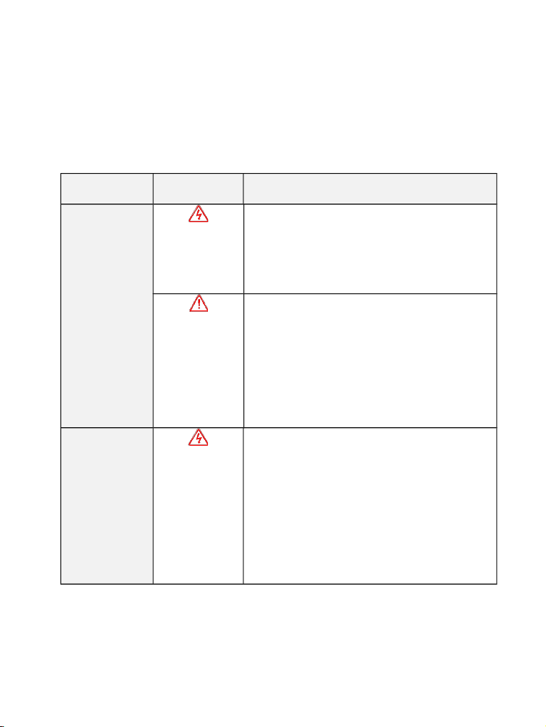
1.2 Safety Information
The use phase Safety class Precaution
Before
Installation Danger
Do not install the product if the package is with ◆
water, or component is missing or broken.
Do not install the product if the label on the ◆
package is not identical to that on the inverter.
Caution
Be careful of carrying or transportation. Risk of ◆
devices damage.
Do not use damaged product or the inverters ◆
missing component .Risk of injury.
Do not touch the parts of control system with ◆
bare hands. Risk of ESD hazard.
Installation
Danger
Installation base shall be metal or other non◆
flammable material. Risk of fire.
Do not install inverter in an environment ◆
containing explosive gases, otherwise there is
danger of explosion.
Do not unscrew the fixing bolts, especially the ◆
bolts with red mark.
Fig 1 1. Models description

7
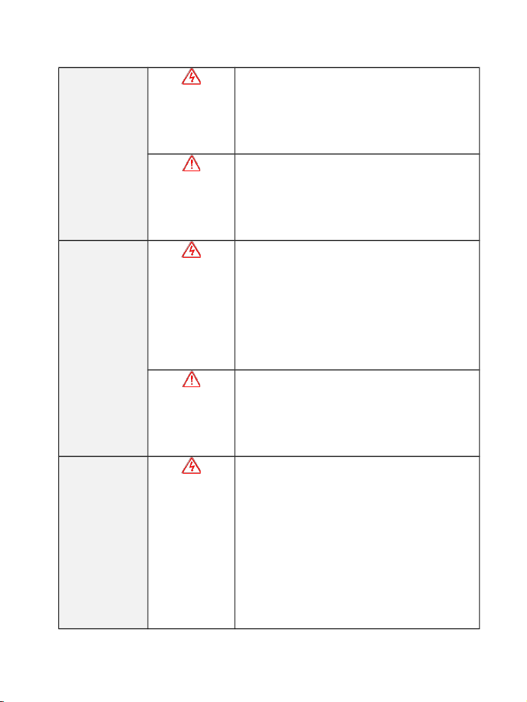
Caution
Do not leave cable strips or screws in the◆
inverter. Risk of inverter damage.
Install the product at the place with less◆
vibration and no direct sunlight.
Consider the installation space for cooling◆
purpose when two or more inverters are placed in
the same cabinet.

8
Wiring
Danger
Wiring must be performed by authorized and ◆
qualified personnel. Risk of danger.
Circuit breaker should be installed between ◆
inverter and the mains. Risk of fire.
Make sure the input power supply has been ◆
completely disconnected before wiring. Failure to
comply may result in personnel injury and/or
equipment damage.
Since overall leakage current of this equipment ◆
may be bigger than 3.5mA, for safety's sake, this
equipment and its associated motor must be well
grounded so as to avoid risk of electric shock.
Never connect the power cables to the output ◆
terminals (U, V, W) of the AC drive. Pay attention
to the marks of the wiring terminals and ensure
correct wiring. Failure to comply will result in
damage to the AC drive.
Install braking resistors at terminals (P+)and ◆
(P or PB) only. Failure to comply may result in
equipment damage.

9
Caution
Since all adjustable frequency AC drives from ◆
our company has been subjected to hi pot test
before delivery, users are prohibited from
implementing such a test on this equipment.
Failure to comply may result in equipment
damage.
Signal wires should to the best of the possibility◆
be away from main power lines. If this cannot be
ensured, vertical cross arrangement shall be
implemented, otherwise interference noise to
control signal may occur.
If motor cables are longer than 100m, it is ◆
recommended output AC reactor be used. Failure
to comply may result in faults.
Before Power
on Danger
Inverter shall be power on only after the front ◆
cover is assembled. Risk of electrical hazard.
Caution
Verify that the input voltage is identical to the ◆
rated voltage of product, correct wiring of input
terminals R, S, T and output terminals U, V, and
W, wiring of inverter and its peripheral circuits,
and all wires should be in good connection. Risk
of inverter damage.
10
After Power on
Danger
Do not open the cover after power. Rick of◆
electrical hazard.
Do not touches any input/output terminals of◆
inverter with bare hands. Rick of electrical hazard.
Caution
If auto tuning is required, be careful of personal◆
injury when motor is running. Risk of accident.
Do not change the defaults of parameters. Risk◆
of devices damage.
During
Operation Danger
Non professionals shall not detect signals◆
during operation. Risk of personal injury or device
damage.
Do not touch the fan or the discharging resistor◆
to check the temperature. Failure to comply will
result in personal burnt.
Caution
Prevent any foreign items from being left in the ◆
devices during operation. Risk of device damage.
Do not control start/stop of inverter by ON/OFF ◆
of contactor. Risk of device damage.
Maintenance
Danger
Maintenance and inspection can only be◆
performed by professionals. Risk of
personal injury.
Maintain and inspect devices after ◆
power is off. Risk of electric hazard.
Repair or maintain the AC drive only ten ◆
minutes after the AC drive is powered off.
This allows for the residual voltage in the

11
capacitor to discharge to a safe value.
Failure to comply will result in personal
injury.
All pluggable components can be ◆
inserted or pulled out only when power has
been turned off.
Set and check the parameters again ◆
after the AC drive is replaced.
General Precautions
1. Constant torque low frequency running
When inverter with induce motor running at long time low speed, the effection of heat
emission will get worse and influence motor using life. If low speed constant torque running
for long time, user have to use Variable frequency motor.
2. Motor insulation test
Perform the insulation test when the motor is used for the first time, or when it is re used
after being stored for a long time, or in a regular check up, in order to prevent the poor
insulation of motor windings from damaging the AC drive. The motor must be disconnected
from the AC drive during the insulation test.
3. Hoist load
In Hoist load application, as the inertia exist, inverter will trip as over current or overvoltage
fault. In the case, braking unit and resistor should be connected.
4. Vibration of mechanical device

12
The AC drive may encounter the mechanical resonance point at some output frequency,
which can be avoided by setting the skip frequency.
5. Voltage sensitive device or capacitor on output side of the AC drive
Do not install the capacitor for improving power factor or lightning protection voltage
sensitive resistor on the output side of the AC drive because the output of the AC drive is
PWM wave. Otherwise, the AC drive may suffer transient overcurrent or even be damaged.
M
变频调速器
U
V
W
KM
6. Derate at Basic frequency setting
When basic frequency is lower than rated frequency, be caution to derate motor avoilding
motor burn.
7. Running at over 50 Hz
If the AC drive is required to run at over 50 Hz, motor viberation and noise will increase.
Consider the capacity of the machine.
8. Thermal protection of motor
AC DRIVE
Fig 1 2. Inverter not allowed to connect capacitor
13
If the rated capacity of the motor selected does not match that of the AC drive,
especially when the AC drive's rated power is greater than the motor's, adjust the motor
protection parameters on the operation panel of the AC drive or install a thermal relay in the
motor circuit for protection.
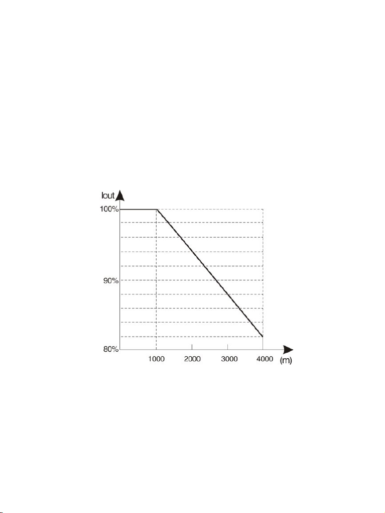
9. Altitude and de rating
In places where the altitude is above 1000 m and the cooling effect reduces due to thin air, it
is necessary to de rate the AC drive.
10. Protection class
DGI900 protection level is IP20 when inverter with keypad.
Fig 1 3. Inverter output current derating and Altitude

14
Disposal
The electrolytic capacitors on the main circuits and PCB may explode when they are burnt.
Poisonous gas is generated when the plastic parts are burnt. Treat them as ordinary
industrial waste.

15
Chapter 2 Models and Specifications
2.1 Models
DGI900 series inverter has 2 kinds of voltage levels, 220V and 380V. The Power range is
from 0.4KW to 450KW. Models of DGI900 series are shown in Table 2 1.
Table 2 1. Models description
Voltage level Models Rated
capacity(
Rated
output
Applicable
motor(KW)
220V
Single
phase
DGI900 2S0004G
1.1
3.0
0.4
DGI900 2S0007G
1.5
4.7
0.75
DGI900 2S0015G
2.8
7.5
1.5
DGI900 2S0022G
3.8
10.0
2.2
220V
Three phase
DGI900 2T0015G
3.0
7.0
1.5
DGI900 2T0022G
4.0
10.0
2.2
380V
Three phase
DGI900 4T0007G
1.5
2.5
0.75
DGI900 4T0015G
2.5
4.0
1.5
DGI900 4T0022G
DGI900 4T0022P
3.0
6.0
2.2
DGI900 4T0037G
DGI900 4T0037P
5.9
9.6
3.7
DGI900 4T0055G
DGI900 4T0055P
8.5
14.0
5.5
DGI900 4T0075G
DGI900 4T0075P
11
17.0
7.5
DGI900 4T0110G
DGI900 4T0110P
17
25
11
DGI900 4T0150G
DGI900 4T0150P
21.7
32
15
DGI900 4T0185G
DGI900 4T0185P
25.7
39
18.5
DGI900 4T0220G
DGI900 4T0220P
29.6
45
22
DGI900 4T0300G
DGI900 4T0300P
39.5
60
30
DGI900 4T0370G
DGI900 4T0370P
49.4
75
37
DGI900 4T0450G
DGI900 4T0450P
60
91
45
16
DGI900 4T0550G
DGI900 4T0550P
73.7
112
55
DGI900 4T0750G
DGI900 4T0750P
99
150
75
DGI900 4T0900G
DGI900 4T0900P
116
176
90
DGI900 4T1100G
DGI900 4T1100P
138
210
110
DGI900 4T1320G
DGI900 4T1320P
167
253
132
DGI900 4T1600G
DGI900 4T1600P
200
304
160
DGI900 4T1850G
DGI900 4T1850P
234
355
187
DGI900 4T2000G
DGI900 4T2000P
248
377
200
380V
DGI900 4T2200G
DGI900 4T2200P
280
426
220
Three phase
DGI900 4T2500G
DGI900 4T2500P
318
474
250
DGI900 4T2800G
DGI900 4T2800P
342
520
280
DGI900 4T3150G
DGI900 4T3150P
390
600
315
DGI900 4T3500G
DGI900 4T3500P
435
660
350
DGI900 4T4000G
DGI900 4T4000P
493
750
400
DGI900 4T4500G
DGI900 4T4500P
560
850
450
2.2 Specifications
Items Specifications
Input Rated
Voltage
Single phase220V, three phase 220V, three phase
380V;50Hz/60Hz
Range Voltage: ±20% voltage unbalance rate:<3%; frequency: ±5%
Output Rated
voltage
0~200V/220V/380V
Frequency
range
0Hz~500Hz
Frequency
resolution
0.01Hz

17
Overload
ability
150% rated current for1minute, 180% rated current for3 seconds
Control function
Modulation
modes
Optimized space voltage vector SVPWM modulation
Control
mode
V/F, Sensor less vector and Closed loop vector control
Frequency
accuracy
Digital setting: The highest frequency×± 0.01% Analog
setting: The highest frequency ×±0.2%
Frequency
resolution
Digital setting: 0.01Hz; Analog setting: The highest frequency×
0.1%
Start
frequency
0.40Hz~20.00Hz
Torque
boost
Auto torque boost, manual torque boost 0.1%~30.0%
V/F curve Five ways: constant torque V/F curve, 1 kind of user defined
V/F curve ,3 kinds of down torque curve(2.0/1.7/1.2times the
power)
Acc./Dec.
curve
Two ways: linear Acc./Dec.,S curveAcc./Dec.;7 kinds of
Acc./Dec. time,
Time unite (minute/second) optional, max time: 6000 minutes.
DC braking DC braking start frequency:0~15.00Hz
braking time:0~60.0s braking current:0~80%
Energy
consuming
braking
Below 22KW drive built in energy consuming braking unit, 30
37KW built in braking unit optional, external braking resistor is
optional.

18
Control
function
Jog
running
Jog frequency range:0.1Hz~50.00Hz, JOG Acc./Dec. time:
0.1~60.0s
PI built in Easily constitute a close loop control system
Multi stage
speed
running
Multi stage speed running available through built in PLC or
control terminals
Textile
swing
frequency
Swing frequency available with preset and central frequency
adjustable
Auto
voltage
regulation
Keep a stable voltage automatically when the grid voltage
transients
Auto
energy
saving
running
Saving energy by auto optimizing V/F curve according to the
load
Auto
current
limiting
Auto current limiting to prevent frequent over current fault trip
Multi
pumps
control
With water supply card, the function can implement multi pumps
constant pressure water supply
Communic
ation
4 field bus: Modbus, Profibus, CANlink, CANopen

19
Running
function
Running
command
channel
Control panel : control terminal :serial port :3 channels
switchable
Frequency
setting
channel
Control panel potentiometer setting: ▲ ▼、control panel keys
setting; Function code setting: Serial port setting; Terminal
up/down setting: Input Analog voltage setting: Input Analog
current setting: Input pulse setting; Combination ways setting;
Above ways are switchable.
Switch
input
channel
FWD/REV command: 8channels programmable switch inputs,
35kinds of function can be set separately
Analog
input
channel
4~20mA: 0 10V: 2 optional analog inputs
Analog
output
channel
4~20mA or 0~10V optional, setting frequency and output
frequency ,etc feature output
Switch/puls
e output
channel
2 channels Programmable open collectors output, 2 channels
relays output, 1 channel 0~20KHz pulse output
Control panel
LED digital
display
Display setting frequency, output voltage, output current, etc.
External
meter
display
Display output frequency, output current, output voltage, etc.
Key lock All the keys can be locked

20
Parameter
copy
Function code parameters are able to be copied between
inverters when use remote control panel。
Protection function Overcurrentprotection:overvoltageprotection:undervoltageprotec
tion:overheating protection: overload protection, etc.
Optional parts Braking unit: remote control panel: cable: panel mounting feet,
etc.
Environment
Environment Indoors, free from direct sunlight, dust, corrosive gas, oil mist,
steam, water dropper salt, etc
Altitude Lower than 1000m (derating is necessary above 1000m)
Ambient
temperature
-10℃~+40℃
Humidity <95%RH, no condensation
Vibration Lower than 5.9m/s (0.6g)
Storage
temperature
-20℃~+60℃
Structure Protection
level
IP20(In the selection of state display unit or the keyboard
state)
Cooling Forced air cooling
Installation Wall mounted; Floor mounted
Other manuals for DGI900
1
Table of contents
Other degdrive DC Drive manuals

Popular DC Drive manuals by other brands

Bosch
Bosch REXROTH HYDROTRAC GFT 8000 operating instructions

Siemens
Siemens SINAMICS S120 Getting started

HAUTAU
HAUTAU SM 101 Installation and operating instructions

Rockwell Automation
Rockwell Automation Allen-Bradley PowerFlex 755 Original instructions

Idex
Idex MICROPUMP EAGLEDRIVE EMSN Series Installation, operation and warranty information

Siemens
Siemens 3TL60 operating instructions


